Page 1162 of 1273
Page 1163 of 1273

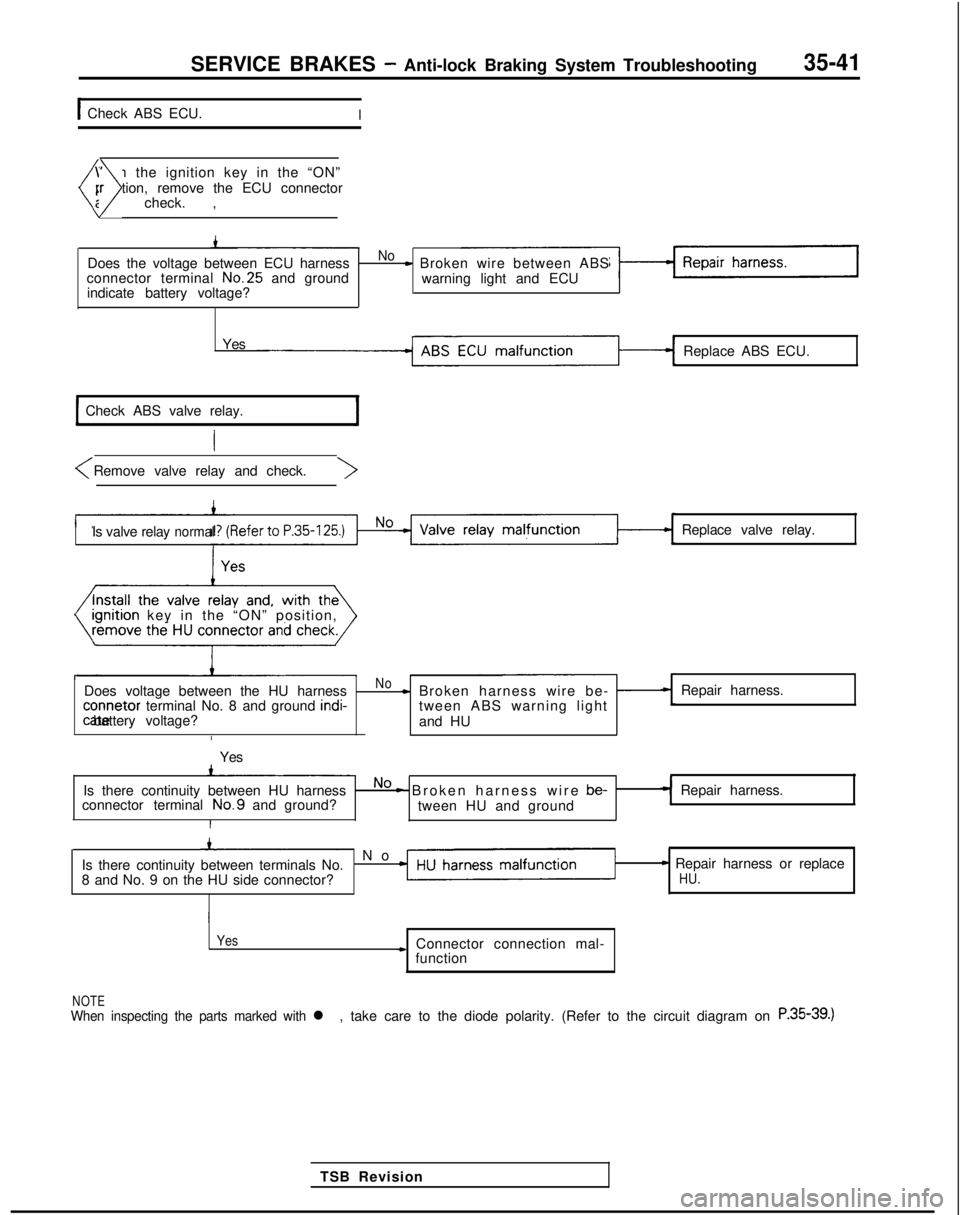
SERVICE BRAKES - Anti-lock Braking System Troubleshooting35-41
1 Check ABS ECU.I
W
ith the ignition key in the “ON”
position, remove the ECU connector
(nd check. ,)
Does the voltage between ECU harnessNo- Broken wire between ABS
connector terminal No.25
and ground
warning light and ECU
indicate battery voltage?
Yes Replace ABS ECU.
Check ABS valve relay.
Is valve relaynormalReplace valve relay.
I
rgnrtron key in the “ON” position,
Does voltage between the HU harness
No- Broken harness wire be- -Repair harness. connetor
terminal No. 8 and ground indi-
tween ABS warning lightcate battery voltage?
and HU
I
Yes
Is there continuity between HU harness
No - Broken harness wire be-
Repair harness.
connector terminal No.9
and ground?
tween HU and ground
I
’ N
o
Is there continuity between terminals No.
8 and No. 9 on the HU side connector?
- Repair harness or replaceHU.
Yes
* Connector connection mal- function
NOTEWhen inspecting the parts marked with l ,take care to the diode polarity. (Refer to the circuit diagram on R.S5-39.)
TSB Revision
Page 1165 of 1273
Page 1166 of 1273
SERVICE BRAKES - Anti-lock Braking System Troubleshooting35-45
DABS warning light blinks once after the ignition key is turned to the “\
ON” positi??. It
illuminates in the “START” position and blinks once again when tur\
ned to the “ON” posItron.
[Explanation]
When power flows, the ABS ECU turns on theharness between the ECU and the warning light, the
warning light for approximately 1 sec. while itlight illuminates only when the valve relay is off in
performs a valve relay test. If there is a break in thethe valve relay test, etc.
El
ABS ECU
11 ,* (3 14
1 5 j 6 1 ,I 8 I 9)10111112113114115l161171~8)[19~0p1l22~3lz4125126127129l29l,ol31l32l33l~l35l
‘1. Non-Turbo . Turbo‘2: Non-Turbo 14AO662
Removehydraulic unitconnector andABS-ECUconnector and inspect atthe ABS-ECUharness \side
connect:/
-.
TSB Revision
Yes
Replace ABS ECU.I
Page 1167 of 1273

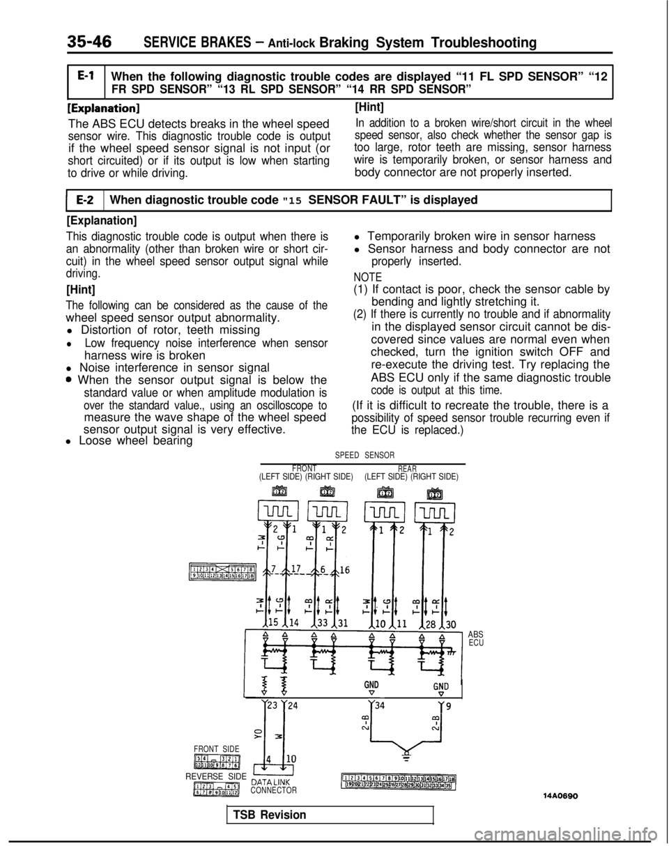
35-46SERVICE BRAKES - Anti-lock Braking System TroubleshootingE-l
When the following diagnostic trouble codes are displayed “11 FL SPD \
SENSOR” “12
FR SPD SENSOR” “13 RL SPD SENSOR” “14 RR SPD SENSOR”
[Explanation] [Hint]
The ABS ECU detects breaks in the wheel speedIn addition to a broken wire/short circuit in the wheel
sensor wire. This diagnostic trouble code is output
if the wheel speed sensor signal is not input (or
speed sensor, also check whether the sensor gap is
too large, rotor teeth are missing, sensor harness
short circuited) or if its output is low when starting wire is temporarily broken, or sensor harness and
to drive or while driving.
body connector are not properly inserted.
E-2When diagnostic trouble code "15 SENSOR FAULT” is displayed
[Explanation]
This diagnostic trouble code is output when there is
an abnormality (other than broken wire or short cir-
cuit) in the wheel speed sensor output signal while
driving.
[Hint]
The following can be considered as the cause of the
wheel speed sensor output abnormality. l Distortion of rotor, teeth missing
lLow frequency noise interference when sensor
harness wire is broken
l Noise interference in sensor signal
0 When the sensor output signal is below the
standard value or when amplitude modulation is
over the standard value., using an oscilloscope to
measure the wave shape of the wheel speed
sensor output signal is very effective.
l Loose wheel bearing l Temporarily broken wire in sensor harness
l Sensor harness and body connector are not
properly inserted.
NOTE
(1) If contact is poor, check the sensor cable by
bending and lightly stretching it.
(2) If there is currently no trouble and if abnormality
in the displayed sensor circuit cannot be dis-
covered since values are normal even when
checked, turn the ignition switch OFF and
re-execute the driving test. Try replacing the
ABS ECU only if the same diagnostic trouble
code is output at this time.
(If it is difficult to recreate the trouble, there is a
possibility of speed sensor trouble recurring even if
the ECU is replaced.)
SPEED SENSOR
FRONT
REAR(LEFT SIDE) (RIGHT SIDE) (LEFT SIDE) (RIGHT SIDE)
ABS
ECU
GNDG!D
r23 )‘24 ;34Y9
FRONT SIDE
REVERSE SIDE DATA LlNK
CONNECTOR
14A0690
TSB Revision
Page 1169 of 1273
![MITSUBISHI GALANT 1989 Service Repair Manual 35-48SERVICE BRAKES - Anti-lock Braking System Troubleshooting
I IE-3When diagnostic trouble code “21 G SENSOR” is displayedI
[Explanation]
The ABS ECU outputs this diagnostic trouble code
in the MITSUBISHI GALANT 1989 Service Repair Manual 35-48SERVICE BRAKES - Anti-lock Braking System Troubleshooting
I IE-3When diagnostic trouble code “21 G SENSOR” is displayedI
[Explanation]
The ABS ECU outputs this diagnostic trouble code
in the](/manual-img/19/57312/w960_57312-1168.png)
35-48SERVICE BRAKES - Anti-lock Braking System Troubleshooting
I IE-3When diagnostic trouble code “21 G SENSOR” is displayedI
[Explanation]
The ABS ECU outputs this diagnostic trouble code
in the following cases.
lOFF trouble turning G sensor OFF (It is judged
that the
G sensor continues to be OFF for more
than approximately 13 seconds except when the
vehicle is stopped or when there is stop light
switch input.
lWhen there is a broken wire or short circuit in
the harness for the
G sensor system.
ABSPOWERRELAY
MAIN FUSIBLEIGNITIONLINK @SWITCH (IG2)
G-SENSOR
q
ABS ECU
II21314 15161 ~/819110111l12l1P/14l15~~6l17l16~~19120121122123l24125l26l27128129/30131j32b3134(15~14AO702
Is G sensor normal?(Refer to P.35-132.)
NoReplace G sensor.
1 Yes
Remove the ABS ECUconnector and check atthe harness connector.
I
With the ignition key “ON”No m The harness between thedoes the voltage betweenG sensor and the ABS
terminal No.6
and ground
ECU is broken.
indicate battery voltage?
Yes
*
Repair harness.
Replace ABS ECU.
1 TSB Revision
Page 1170 of 1273
![MITSUBISHI GALANT 1989 Service Repair Manual SERVICE BRAKES - Anti-lock Braking System Troubleshooting35-49
1 E-4 1 When diagnostic trouble code “22 STOP SW” is displayed
[Explanation]
The ABS ECU outputs this diagnostic trouble code
in the MITSUBISHI GALANT 1989 Service Repair Manual SERVICE BRAKES - Anti-lock Braking System Troubleshooting35-49
1 E-4 1 When diagnostic trouble code “22 STOP SW” is displayed
[Explanation]
The ABS ECU outputs this diagnostic trouble code
in the](/manual-img/19/57312/w960_57312-1169.png)
SERVICE BRAKES - Anti-lock Braking System Troubleshooting35-49
1 E-4 1 When diagnostic trouble code “22 STOP SW” is displayed
[Explanation]
The ABS ECU outputs this diagnostic trouble code
in the following cases.
lStop light switch may remain on for more than
15 minutes without the ABS functions.
lThe harness wire for the stop light switch maybe open.
[Hint]
If the stop light operates normal, the ABS harness
wire for the stop light switch input circuit to the ECU
is broken or there is a malfunction in the ABS ECU.
SUB FUSIBLELINK 0
WITH
AUTO-CRUISE CONTROL
SWITCH -G
_.ABSECU
F-l
14A0663
Do the stop lights light up - Noand go out normally?~ Check the stop light re-lated circuit and repairproblem spots.
Yes
connect the ABS EC
connector and inspect at
the harness side connec-
When the brake pedal isNoHarness wire betweenpressed forcefully, does thevoltage between connectorstop light switch and ABSECU is broken.terminal No. 29 and groundindicate battery voltage?
Yes
1
Repair harness.
1
Malfunction of ABS ECU Replace ABS ECU.I
Page 1174 of 1273

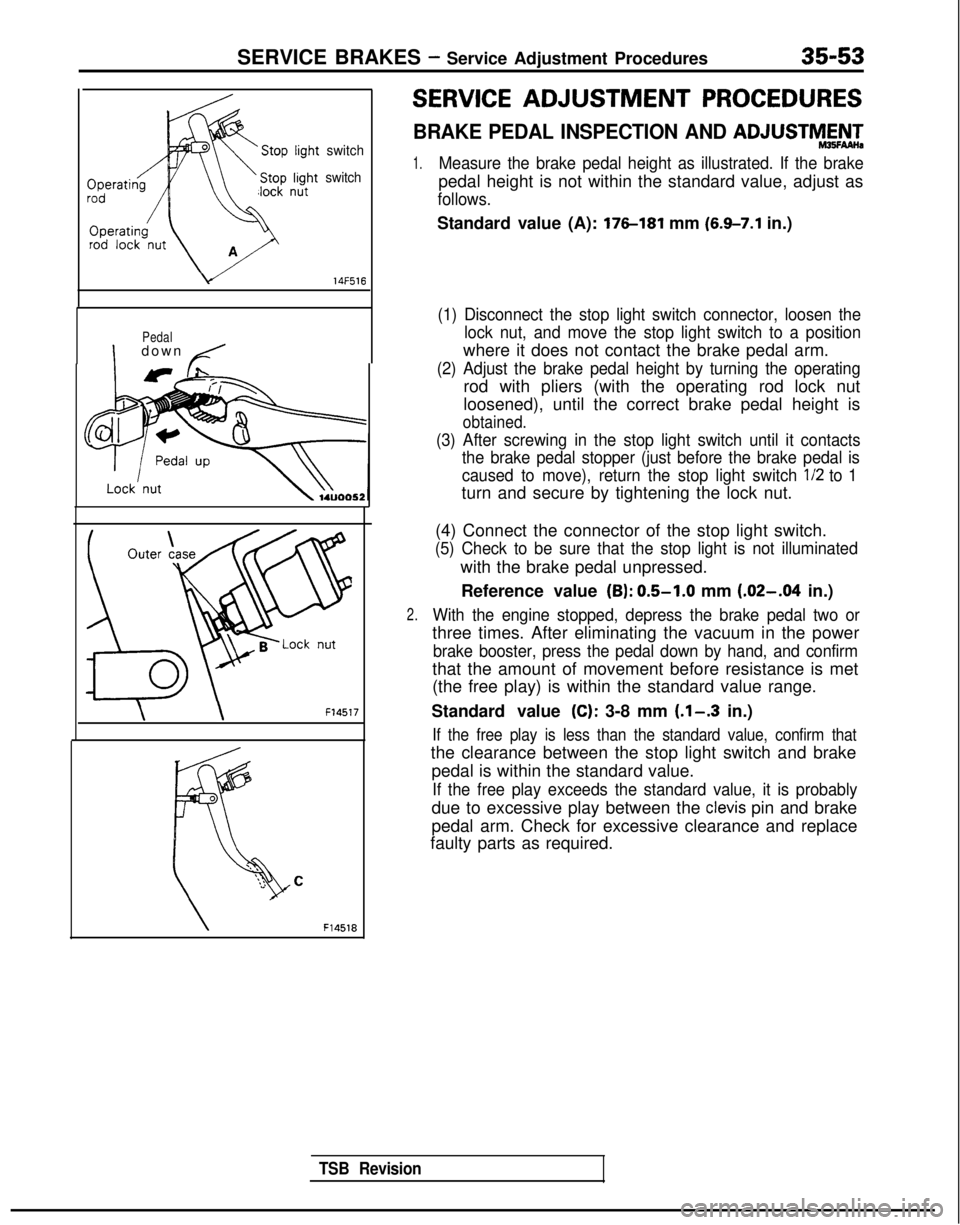
SERVICE BRAKES - Service Adjustment Procedures35-53
switch
switch
c/ 14F516
Pedal
Idown /
\ \
F14517
TSB Revision
F14518
SERVICE ADJUSTMENT PROCEDURES
BRAKE PEDAL INSPECTION AND ADJUSTMAN-
1.Measure the brake pedal height as illustrated. If the brake
pedal height is not within the standard value, adjust as
follows.
Standard value (A): 176-181 mm (6.9-7.1 in.)
(1) Disconnect the stop light switch connector, loosen the
lock nut, and move the stop light switch to a position
where it does not contact the brake pedal arm.
(2) Adjust the brake pedal height by turning the operating
rod with pliers (with the operating rod lock nut
loosened), until the correct brake pedal height is
obtained.
(3) After screwing in the stop light switch until it contactsthe brake pedal stopper (just before the brake pedal is
caused to move), return the stop light switch l/2
to 1
turn and secure by tightening the lock nut.
2.
(4) Connect the connector of the stop light switch.
(5) Check to be sure that the stop light is not illuminated
with the brake pedal unpressed.
Reference value
(B): 0.5-1.0 mm (.02-.04 in.)
With the engine stopped, depress the brake pedal two or
three times. After eliminating the vacuum in the power
brake booster, press the pedal down by hand, and confirm
that the amount of movement before resistance is met
(the free play) is within the standard value range.
Standard value
(C): 3-8 mm (.l-.3 in.)
If the free play is less than the standard value, confirm that
the clearance between the stop light switch and brake pedal is within the standard value.
If the free play exceeds the standard value, it is probably
due to excessive play between the clevis pin and brake
pedal arm. Check for excessive clearance and replace
faulty parts as required.