1989 MITSUBISHI GALANT light
[x] Cancel search: lightPage 1148 of 1273
SERVICE BRAKES -Anti-lock Braking System Troubleshooting35-27
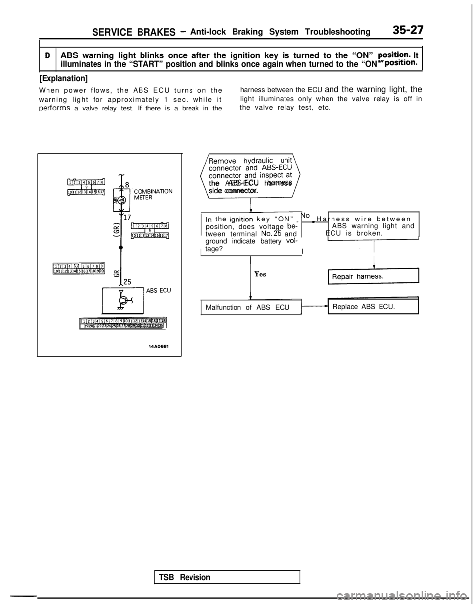
DABS warning light blinks once after the ignition key is turned to the “\
ON” yFsiti?r!. It
illuminates in the “START” position and blinks once again when tur\
ned to the “ONpostilon.
[Explanation]
When power flows, the ABS ECU turns on th
e
harness between the ECU and the warning light, the
warning light for approximately 1 sec. while it light illuminates only when the valve relay is off in
performs a valve relay test. If there is a break in thethe valve relay test, etc.
TSB Revision
-.14AO681
Remove hydraulic unit
connector and ABS-ECU
connector and inspect at
L---J
the ABS-ECU harness
side connector.
In the ignition key “ON” _ No c Harness wire between
position, does voltage
be-ABS warning light and
tween terminal No.25
and ECU is broken.
ground indicate battery
vol-tage? I III
Yes
Malfunction of ABS ECU Replace ABS ECU.
Page 1149 of 1273
35-28SERVICE BRAKES - Anti-lock Braking System Troubleshooting
E-l
I I
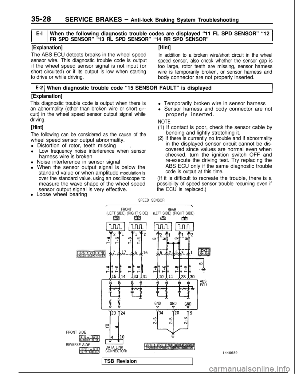
When the following diagnostic trouble codes are displayed “11 FL SPD \
SENSOR” “12
FR SPD SENSOR” “13 RL SPD SENSOR” “14 RR SPD SENSOR”I
[Explanation]
The ABS ECU detects breaks in the wheel speed
sensor wire. This diagnostic trouble code is output
if the wheel speed sensor signal is not input (or
short circuited) or if its output is low when starting
[Hint]
In addition to a broken wire/short circuit in the wheel
speed sensor, also check whether the sensor gap is
too large, rotor teeth are missing, sensor harness
wire is temporarily broken, or sensor harness and
to drive or while driving.
body connector are not properly inserted.
E-2 1 When diagnostic trouble code “15 SENSOR FAULT” is displayed
[Explanation]
This diagnostic trouble code is output when there isl Temporarily broken wire in sensor harness
an abnormality (other than broken wire or short cir-
cuit) in the wheel speed sensor output signal while
l Sensor harness and body connector are not
properly inserted.
driving.NOTE
[Hint](1) If contact is poor, check the sensor cable by
The following can be considered as the cause of thebending and lightly stretching it.
wheel speed sensor output abnormality.
(2) If there is currently no trouble and if abnormality
l Distortion of rotor, teeth missing in the displayed sensor circuit cannot be dis-,
lLow frequency noise interference when sensorcovered since values are normal even when
harness wire is broken checked, turn the ignition switch OFF and
l Noise interference in sensor signal re-execute the driving test. Try replacing the
l When the sensor output signal is below the ABS ECU only if the same diagnostic trouble
standard value or when amplitude modulation is
code is output at this time.
over the standard value,.using an oscilloscope to(If it is difficult to recreate the trouble, there is a
measure the wave shape of the wheel speed
possibility of speed sensor trouble recurring even if
sensor output signal is very effective.the ECU is replaced.)
l Loose wheel bearing
SPEED SENSOR
/~7FRONTREAR(LEFT SIDE) (RIGHT SIDE)(LEFT SIDE) (RIGHT SIDE)ggj ggjjm m
GND y23
y24
FRONT SIDE
REVERSDATA LINKCONNECTOR
1 TSB Revision
1440689
Page 1151 of 1273
![MITSUBISHI GALANT 1989 Service Repair Manual 35-30SERVICE BRAKES - Anti-lock Braking System Troubleshooting
E-3When diagnostic trouble code “22 STOP SW” is displayed1
[Explanation][Hint]
The ABS ECU outputs this diagnostic trouble codeIf the MITSUBISHI GALANT 1989 Service Repair Manual 35-30SERVICE BRAKES - Anti-lock Braking System Troubleshooting
E-3When diagnostic trouble code “22 STOP SW” is displayed1
[Explanation][Hint]
The ABS ECU outputs this diagnostic trouble codeIf the](/manual-img/19/57312/w960_57312-1150.png)
35-30SERVICE BRAKES - Anti-lock Braking System Troubleshooting
E-3When diagnostic trouble code “22 STOP SW” is displayed1
[Explanation][Hint]
The ABS ECU outputs this diagnostic trouble codeIf the stop light operates normal, the ABS harness
in the following cases.wire for the stop light switch input circuit to the ECU
lStop light switch may remain on for more thanis broken or there is a malfunction in the ABS ECU.
15 minutes without the ABS functions.
lThe harness wire for the stop light switch may be open.
SUB FUSIBLELINK @
ABSECU
[1121314/5161716~9~10~11~12~13~14~15(16~17~18]~19DOC1122~3~4125l26~27~2~2913013ll3Z~33(341351
Do the stop lights light up
and go out normally?No c Check the stop light re-
lated circuit and repair
problem spots.
Yes
connector and inspectat
the harness side connec-
When the brake pedal is
_NoHarness wire between
pressed forcefully, does the
voltage between connector stop light switch and ABS
ECU is broken.
terminal No. 29 and ground
indicate battery voltage?
c
Repair harness.
Yes r
Malfunction of ABS ECU Replace ABS ECU.
I
14AO683
TSB Revision
Page 1155 of 1273
35-34SERVICE BRAKES - Anti-lock Braking System Troubleshooting
TROUBLESHOOTING (ABS-AWD)
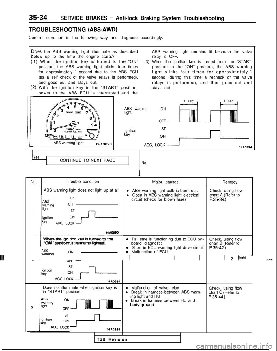
Confirm condition in the following way and diagnose accordingly.
c
P
t:
1
-)oes
the ABS warning light illuminate as described
elow up to the time the engine starts?
1) When the ignition key is turned to the “ON”
position, the ABS warning light blinks four times
for approximately
1 second due to the ABS ECU
(as a self check of the valve relays is performed),
and goes out and stays out.
2) W
ith the ignition key in the “START” position,
power to the ABS ECU is interrupted and the ABS warning light remains lit because the valve
relay is OFF.
(3) When the ignition key is turned from the “START’ position to the “ON” position, the ABS warning
light blinks four times for approximately
1
second (during this time a recheck of the valve
relays is performed), and then goes out and
stays out.
,,,\~~\l’l”“F’,r//,,,l/,,
a+’4 4 5r’o, (j /z$$+3,,,,%&73,
:
f=&L-gy
82
1cJz
x 1000
rimonUILEAED nxL GNL”Oyg@O@~ 2F
ABS
warnmg’l~ght66A0093
ABS warning
lightONI
OFF
Ignitionkey
ACC, LOCK
114AO594
YesCONTINUE TO NEXT PAGENo
1
No.Trouble condition
ABS warning light does not light up at all.
1
ABSwarning
light
Ignition
keyACC, ON
OFFLOCK 1
I
When the lgnltlon
key IS turned to the
“ON” position, it remains lighted.
ABS warnina
ON , l Short in ECU warning light drive circuit
l Malfunction of ECU
-“l-l- -III
ignitionkey
ACC. LO!?-14AO591
Major causes
l ABS warning light bulb is burnt out.
l Open in ABS warning light electrical circuit (check for blown fuse)
l Fail safe is functioning due to ECU on-
board diagnostic
Does not illuminate when ignition key is
in “START” position. l Malfunction of valve relay
l Break in harness between ABS warn-
ing light and HU
l Break in harness between HU and
14AO595
Remedy
Check, using flow
chart A (Refer to
P.35-39.)
Check, using flow
chart B (Refer toP.35-42.)
1 2 /light
-
Check, using flow
chart C (Refer to
P.35-44.)
TSB Revision
Page 1156 of 1273
SERVICE BRAKES .- Anti-lock Braking System Troubleshooting35-35
No.
4
rBSvarningght
I!Jnitlonkey
L
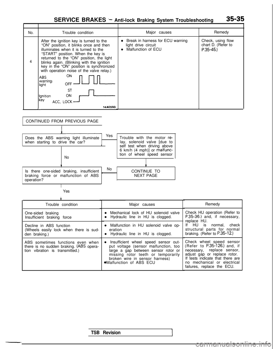
Trouble condition
After the ignition key is turned to the “ON” position, it blinks once and then
illuminates when it is turned to the “START” position. When the key is
returned to the “ON” position, the light
blinks again. (Blinking with the ignition
key in the “ON” position is synchronized
with operation noise of the valve relay.)
14A0593
CONTINUED FROM PREVIOUS PAGE Major causes
l Break in harness for ECU warning light drive circuit
l Malfunction of ECU
when starting to drive the car? Does the ABS warning light illuminate
Yes
Trouble with the motor
re-lay, solenoid valve [due to1self test when driving above
6 km/h (4 mph)] or malfunc-
Notion of wheel speed sensor
tt
Is there one-sided braking, insufficientNo
braking force or malfunction of ABS c
CONTINUE TO
NEXT PAGE
operation?
Yes
4
Trouble condition
One-sided braking Insufficient braking force
Decline in ABS function
(Wheels easily lock when there is sud-
den braking.)
ABS sometimes functions even when
there is no sudden braking.
(ABS opera-
tion vibration is transmitted.) Major causes
l Mechanical lock of HU solenoid valve
l Hydraulic line in HU is clogged.
l Malfunction in HU solenoid valve op- eration
l Hydraulic line in HU is clogged.
l Insufficient wheel speed sensor out- put voltage (sensor malfunction, too
large a gap between sensor rotor or
missing rotor teeth or temporarily
broken wire in sensor harness) 8 Malfunction of ABS ECU Remedy
Check, using flow
chart D. (Refer to
P.35-45.)
TSB Revision1
Remedy
Check HU operation (Refer to
P.35-36.) and, if necessary,
replace HU. If HU is normal, check
structural parts for normal
braking. (Refer to
P.35-12.)
Check wheel speed sensor
(Refer to P.35-126.) and, if
necessary, replace sensor,
adjust gap or replace rotor. If tests indicate that there are
no mechanical or electrical
failures, replace the ECU.
Page 1158 of 1273
SERVICE BRAKES - Anti-lock Braking System Troubleshooting35-37
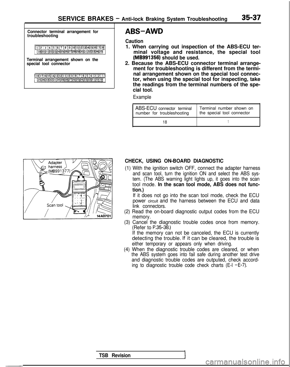
Connector terminal arrangement for
troubleshooting
[l I2 / 3 14 15 1617 16 I9[10~11~12(13~14~15(16~17[16j[lQ~20~21~22~23~24)25~26~27~28(29130~31~32~33~34~35~
Terminal arrangement shown on the
special tool connector
-.
TSB Revision
ABS-AWD
Caution
1. When carrying out inspection of the ABS-ECU ter-
minal voltage and resistance, the special tool
(MB991356) should be used.
2. Because the ABS-ECU connector terminal arrange- ment for troubleshooting is different from the termi-
nal arrangement shown on the special tool connec-
tor, when using the special tool for inspecting, take
the readings from the terminal numbers of the spe-
cial tool.
Example
ABS-ECU connector terminalTerminal number shown on
number for troubleshooting the special tool connector
181
CHECK, USING ON-BOARD DIAGNOSTIC
(1) With the ignition switch OFF, connect the adapter harness
and scan tool, turn the ignition ON and select the ABS sys-
tem. (The ABS warning light lights up, it goes into the scan
tool mode. In the scan tool mode, ABS does not func-
tion.)
If it does not go into the scan tool mode, check the ECU
power
circuit and the harness between the ECU and data
link connectors.
(2) Read the on-board diagnostic output codes from the ECU
memory.
(3) Cancel the diagnostic trouble codes once from memory. (Refer to
P.35-38.)
If the memory can not be canceled, the ECU is currently
detecting the trouble. If’it can be cleared, the trouble is
either temporary or appears only when driving.
(4) When the diagnostic trouble codes are cleared, or when
the ABS system goes into fail safe during another test drive
and diagnostic trouble codes are outputed, check accord-
ing to diagnostic trouble code check charts (E-l -E-7).
Page 1160 of 1273
![MITSUBISHI GALANT 1989 Service Repair Manual SERVICE BRAKES- Anti-lock Braking System Troubleshooting35-39
AABS warning light does not light at all.1
[Explanation][Hint]
When it does not light up at all, there is a strongIf other warning lighrs MITSUBISHI GALANT 1989 Service Repair Manual SERVICE BRAKES- Anti-lock Braking System Troubleshooting35-39
AABS warning light does not light at all.1
[Explanation][Hint]
When it does not light up at all, there is a strongIf other warning lighrs](/manual-img/19/57312/w960_57312-1159.png)
SERVICE BRAKES- Anti-lock Braking System Troubleshooting35-39
AABS warning light does not light at all.1
[Explanation][Hint]
When it does not light up at all, there is a strongIf other warning lighrs do not light up either, fuse is
possibility that there is trouble with ABS warningprobably blown.
light or with power to the light.
MAIN FUSIBLELINK @of
LA
IGNITIONIGNITSWITCH (IG2)SWIT
-Tr-- -z
ABS POWERRELAY
‘IOct:I
1__--------I,7r
.I
:
,\c
AL1-f.
C.
dU
dr-3
gl”pzElzmq
4
4*I
21\5 ,&A27ABS ECU
;(IGI,
1234
7m5670
1
J/B
7
1COMBINATION
1METER
1r2
gizizgl
*
t
GNOGNDVV
*I:
Non-Turbo
TSB RevisionI
Page 1161 of 1273
SERVICE BRAKES - Anti-lock Braking System Troubleshooting
W
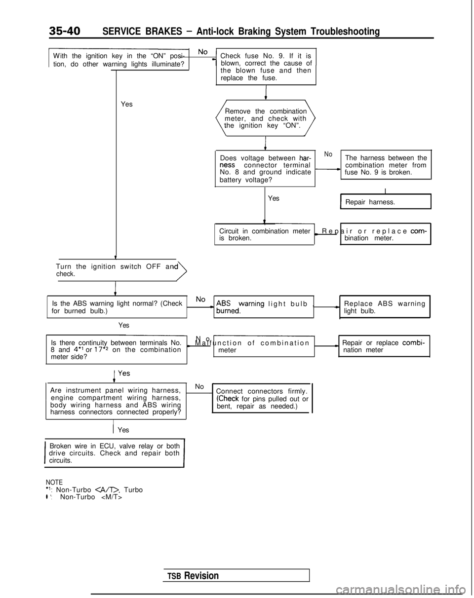
ith the ignition key in the “ON” posi- No
Check fuse No. 9. If it is
tion, do other warning lights illuminate? blown, correct the cause of
-T-
Yesthe blown fuse and then
replace the fuse.I
Remove the combination
meter, and check with
the ignition key “ON”.
I
Does voltage between har-NoThe harness between the ness
connector terminal
No. 8 and ground indicate
-combination meter from
fuse No. 9 is broken.
battery voltage?
I
Yes Repair harness.
Circuit in combination meter
is broken.
L Repair or replace com-
bination meter.
Turn the ignition switch OFF an
check.
I
Is the ABS warning light normal? (CheckNo
for burned bulb.)c A$Eedyrning light bulb
,
c Replace ABS warning
light bulb.
Yes
Is there continuity between terminals No. No -
8 and 4” or 17’2 on the combinationI Malfunction of combinatio
n
meter
I Repair or replace combi-
meter side? nation meter
Are instrument panel wiring harness, No
-~
engine compartment wiring harness, . Connect connectors firmly.
body wiring harness and ABS wiring
(Check for pins pulled out or
harness connectors connected properly? bent, repair as needed.)
I
1 Yes
I
Broken wire in ECU, valve relay or both
drive circuits. Check and repair both
circuits.
I
NOTE‘1: Non-Turbo . Turbol *:Non-Turbo
TSB Revision