1989 MITSUBISHI GALANT light
[x] Cancel search: lightPage 1088 of 1273
REAR SUSPENSION
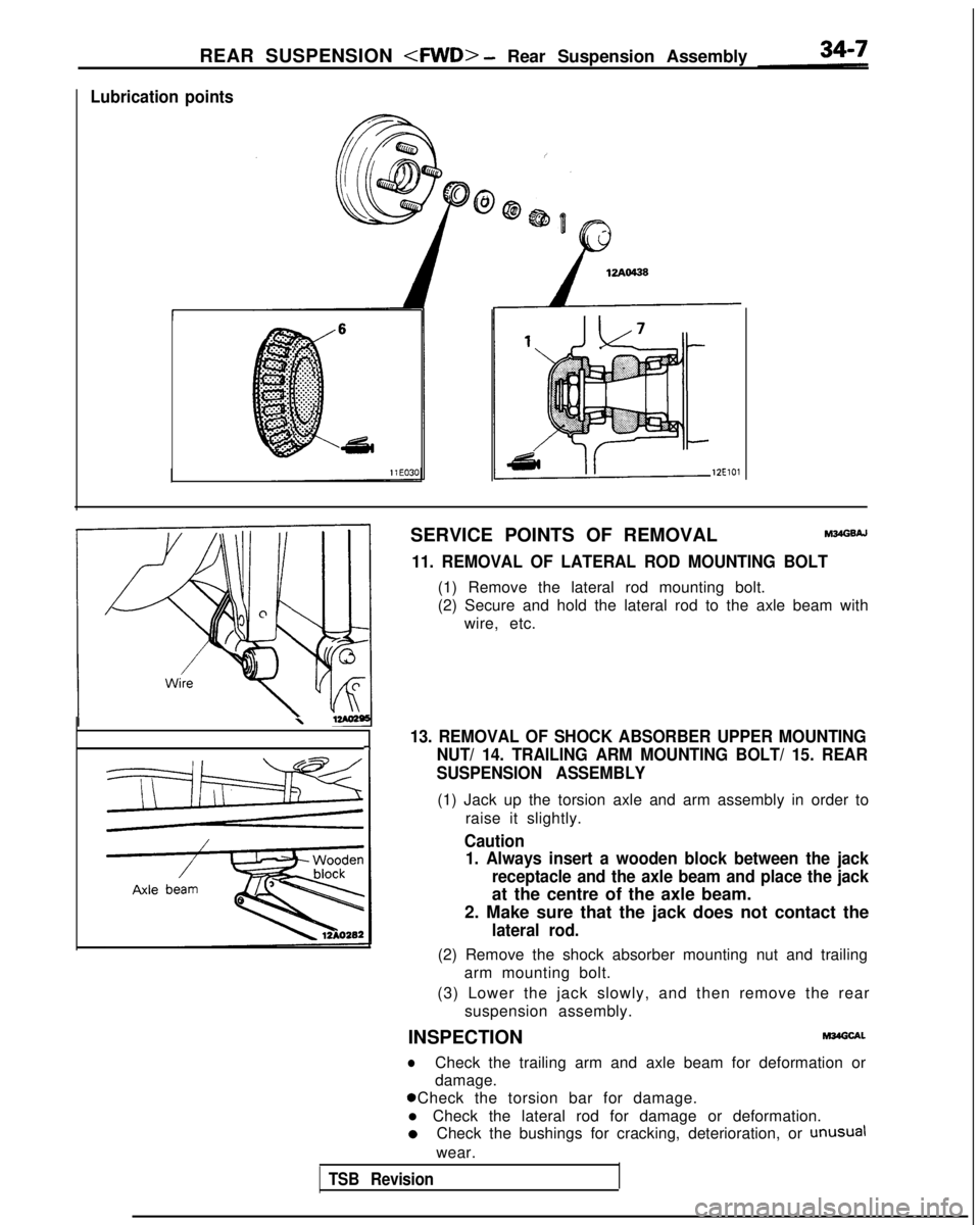
Lubrication points
12ElOl
SERVICE POINTS OF REMOVALM34GsAJ
11. REMOVAL OF LATERAL ROD MOUNTING BOLT
(1) Remove the lateral rod mounting bolt.
(2) Secure and hold the lateral rod to the axle beam with
wire, etc.
\
13. REMOVAL OF SHOCK ABSORBER UPPER MOUNTING-INUT/ 14. TRAILING ARM MOUNTING BOLT/ 15. REAR
SUSPENSION ASSEMBLY
(1) Jack up the torsion axle and arm assembly in order to
raise it slightly.
Caution1. Always insert a wooden block between the jack
receptacle and the axle beam and place the jack
at the centre of the axle beam.
2. Make sure that the jack does not contact the
lateral rod.
(2) Remove the shock absorber mounting nut and trailing arm mounting bolt.
(3) Lower the jack slowly, and then remove the rear suspension assembly.
INSPECTION
M34Glxl.
lCheck the trailing arm and axle beam for deformation or
damage. 0 Check the torsion bar for damage.
l Check the lateral rod for damage or deformation. 0
Check the bushings for cracking, deterioration, or
unusual
wear.
TSB Revision
Page 1092 of 1273
REAR SUSPENSION
SHOCK ABSORBER ASSEMBLY
REMOVAL AND INSTALLATION
hl34NA-A
Pre-removal
and Post-installation Op-
r
*Removal and lnstallatlon of the TrunkSide Trim (Refer to GROUP
52-Trims.)
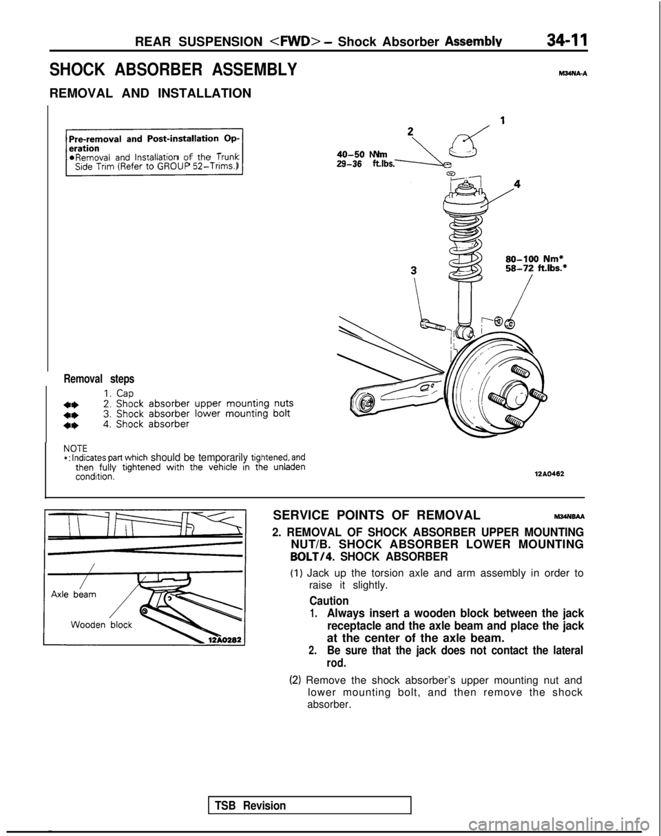
Removal steps
1.Cap
4*2. Shock
absorber
upper
mounting
nuts
4*3. Shock
absorber
lower mounting
bolt
4*4. Shock absorber
29-38 .,bs.-JLzd ’40-50 N
m
80-100 Nm*58-72 ft.lbs.*
NOTE*:
Indicates part which should be temporarily tightened, andthen fully
tightened with
the vehicle in the unladencondition.12AO462
TSB Revision
SERVICE POINTS OF REMOVALM34NsAA
2. REMOVAL OF SHOCK ABSORBER UPPER MOUNTING
NUT/B. SHOCK ABSORBER LOWER MOUNTING
BOLT/4. SHOCK ABSORBER
(1) Jack up the torsion axle and arm assembly in order to
raise it slightly.
Caution
1.Always insert a wooden block between the jack
receptacle and the axle beam and place the jack
at the center of the axle beam.
2.Be sure that the jack does not contact the lateral
rod.
(2) Remove the shock absorber’s upper mounting nut and lower mounting bolt, and then remove the shock
absorber.
Page 1097 of 1273
34-16 REAR SUSPENSION
L
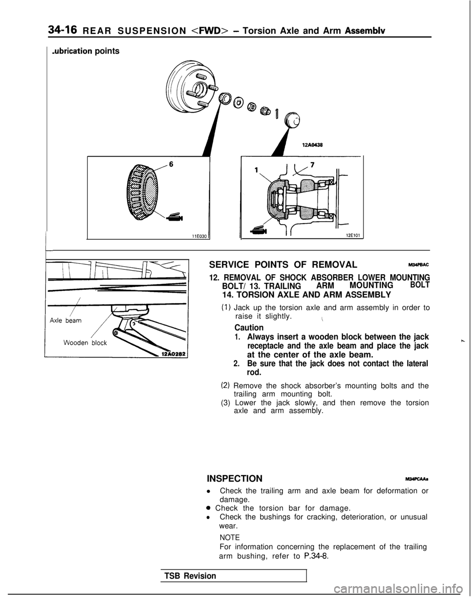
.ubrication points
12ElOl
SERVICE POINTS OF REMOVALM34PBAC
12. REMOVAL OF SHOCK ABSORBER LOWER MOUNTING
BOLT/ 13. TRAILINGARM
MOUNTINGBOLT
14. TORSION AXLE AND ARM ASSEMBLY
(1) Jack up the torsion axle and arm assembly in order to
raise it slightly.
I
Caution
1.Always insert a wooden block between the jack
receptacle and the axle beam and place the jackh
at the center of the axle beam.
2.Be sure that the jack does not contact the lateral
rod.
(2) Remove the shock absorber’s mounting bolts and the trailing arm mounting bolt.
(3) Lower the jack slowly, and then remove the torsion axle and arm assembly.
INSPECTION
l Check the trailing arm and axle beam for deformation or
damage.
0 Check the torsion bar for damage.
lCheck the bushings for cracking, deterioration, or unusual
wear.
NOTE
For information concerning the replacement of the trailing
arm bushing, refer to
P.34-8.
TSB Revision
Page 1107 of 1273
34-26REAR SUSPENSION
I 412AOlOS
J
TSB Revision
SERVICE POINTS OF REMOVAL
4. REMOVAL OF CALIPER ASSEMBLYM?dGSAP
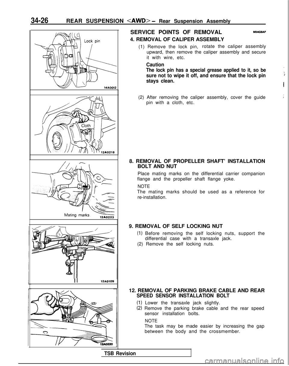
(1) Remove the lock pin, rotate the caliper assembly
upward, then remove the caliper assembly and secure
it with wire, etc.
Caution
The lock pin has a special grease applied to it, so be
sure not to wipe it off, and ensure that the lock pin
stays clean.
I
(2) After removing the caliper assembly, cover the guide pin with a cloth, etc.
8. REMOVAL OF PROPELLER SHAFT’ INSTALLATION BOLT AND NUT
Place mating marks on the differential carrier companion
flange and the propeller shaft flange yoke.
NOTE
The mating marks should be used as a reference for
re-installation.
9. REMOVAL OF SELF LOCKING NUT
(1) Before removing the self locking nuts, support the differential case with a transaxle jack.
(2) Remove the self locking nuts.
12. REMOVAL OF PARKING BRAKE CABLE AND REAR
SPEED SENSOR INSTALLATION BOLT
(1) Lower the transaxle jack slightly.
(2) Remove the parking brake cable and the rear speed sensor installation bolts.
NOTE
The task may be made easier by increasing the gapbetween the body and the crossmember.
Page 1119 of 1273
34-38
REAR SUSPENSION
II12AO109
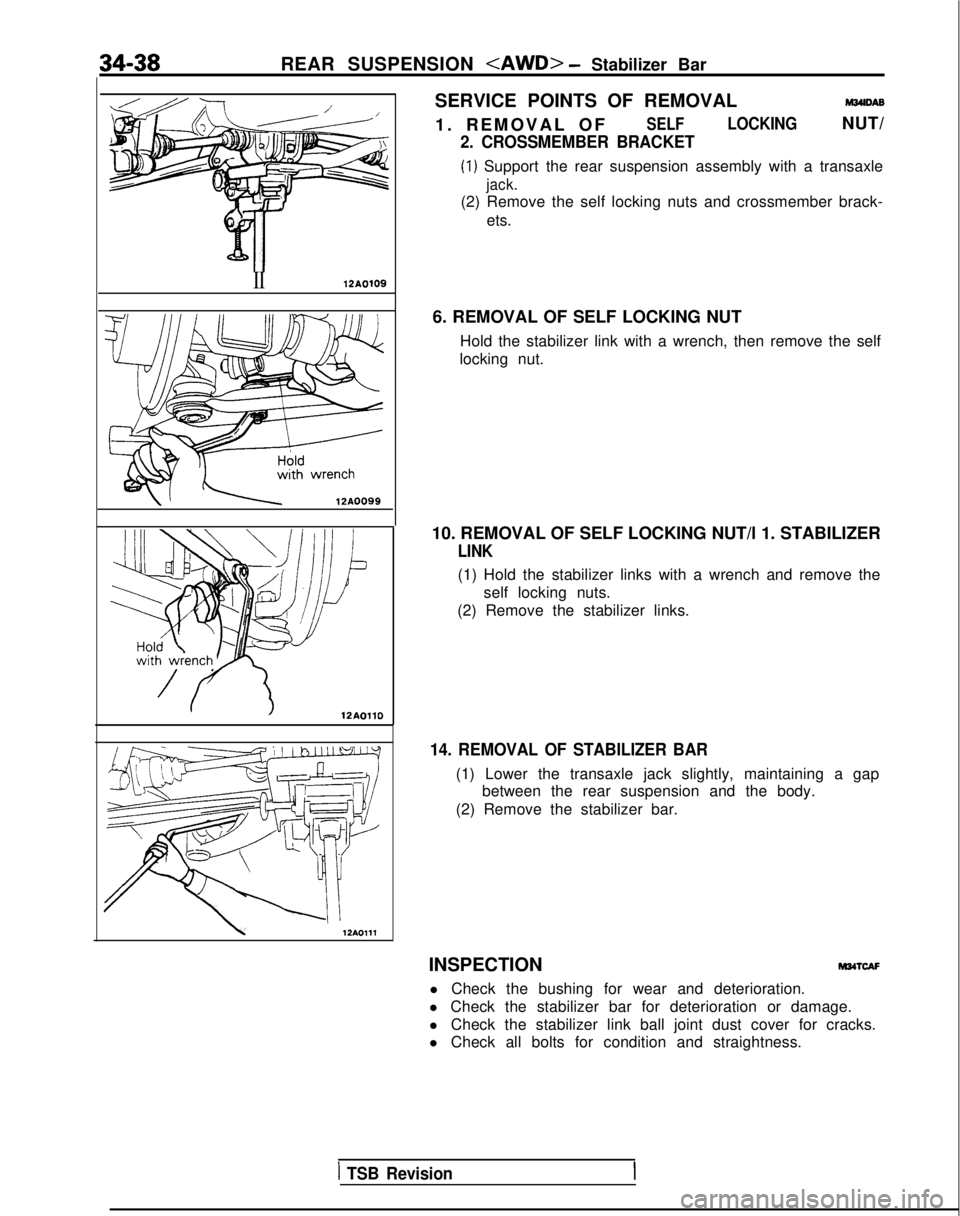
/ 12AOllOSERVICE POINTS OF REMOVAL
M34lDAB
1. REMOVAL O
F
SELFLOCKINGNUT/
2. CROSSMEMBER BRACKET
(1) Support the rear suspension assembly with a transaxle
jack.
(2) Remove the self locking nuts and crossmember brack-
ets.
6. REMOVAL OF SELF LOCKING NUT Hold the stabilizer link with a wrench, then remove the self
locking nut.
10. REMOVAL OF SELF LOCKING NUT/l 1. STABILIZER
LINK
(1) Hold the stabilizer links with a wrench and remove the self locking nuts.
(2) Remove the stabilizer links.
14. REMOVAL OF STABILIZER BAR
(1) Lower the transaxle jack slightly, maintaining a gap between the rear suspension and the body.
(2) Remove the stabilizer bar.
INSPECTION
M34TcAF
l Check the bushing for wear and deterioration.
l Check the stabilizer bar for deterioration or damage.
l Check the stabilizer link ball joint dust cover for cracks.
l Check all bolts for condition and straightness.
1 TSB Revision
Page 1122 of 1273
35-1
SERVICE BRAKES
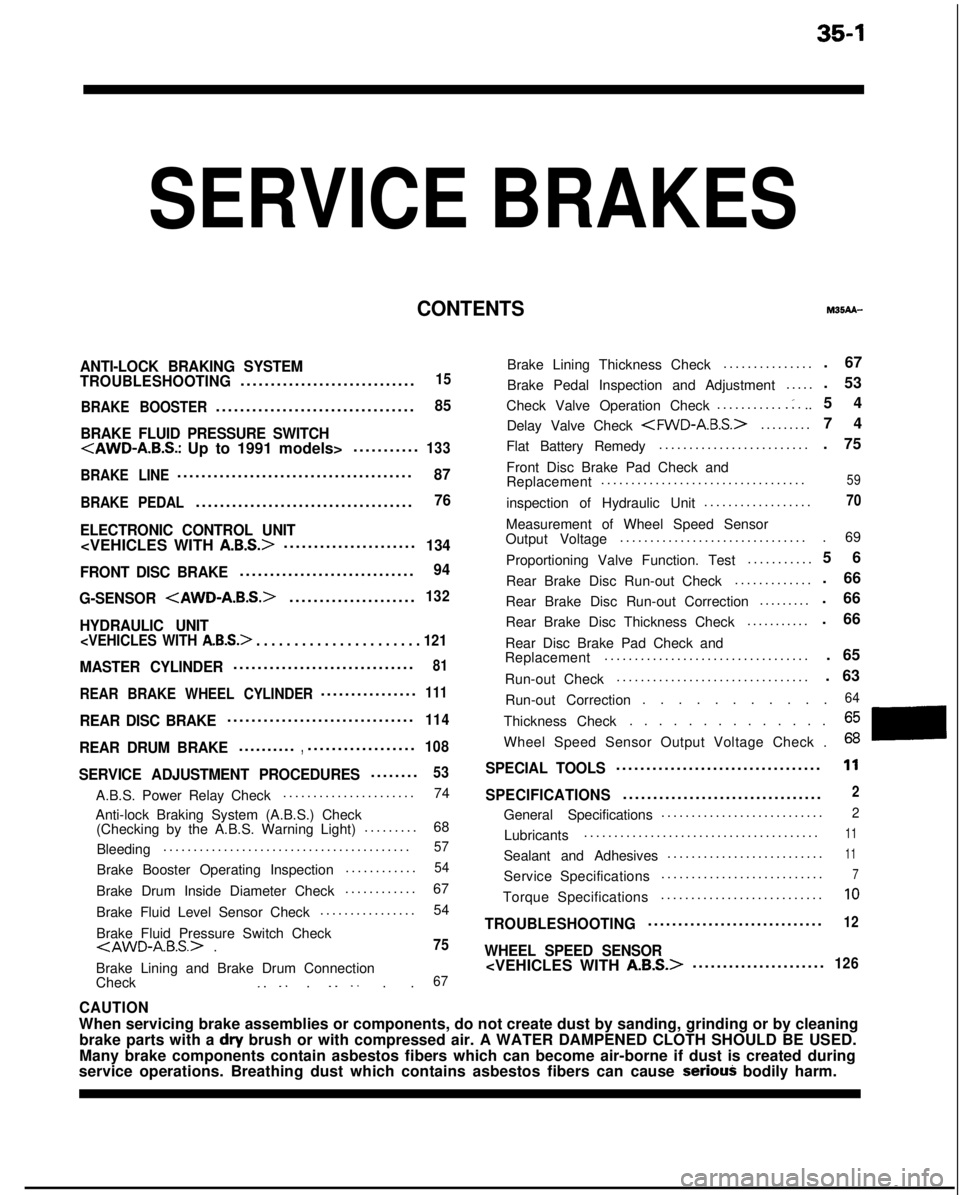
CONTENTSM35AA-
ANTI-LOCK BRAKING SYSTEM
TROUBLESHOOTING............................
.
15
BRAKE BOOSTER
................................
.
85
BRAKE FLUID PRESSURE SWITCH
.
133
BRAKE LINE
......................................
.
87
BRAKE PEDAL...................................
.
76
ELECTRONIC CONTROL UNIT
......................134
FRONT DISC BRAKE
............................
.
94
G-SENSOR
.
132
HYDRAULIC UNIT
. . . . . . . . . . . . . . . . . . . . . . 121
MASTER CYLINDER.............................
.
81
REAR BRAKE WHEEL CYLINDER...............
.
111
REAR DISC BRAKE..............................
.
114
REAR DRUM BRAKE.........
.
,.................
.
108
SERVICE ADJUSTMENT PROCEDURES.......
.
53
A.B.S. Power Relay Check
.....................
.
74
Anti-lock Braking System (A.B.S.) Check (Checking by the A.B.S. Warning Light) .........
68
Bleeding .........................................
57
Brake Booster Operating Inspection
...........
.
54
Brake Drum Inside Diameter Check
...........
.
67
Brake Fluid Level Sensor Check ................
54
Brake Fluid Pressure Switch Check
Brake Lining and Brake Drum Connection
Check _. _. . _. _. . .67
Brake Lining Thickness Check ..............
.
Brake Pedal Inspection and Adjustment .....
Check Valve Operation Check ...........
.:...
Delay Valve Check
.
Flat Battery Remedy .........................
Front Disc Brake Pad Check and
Replacement ..................................
inspection of Hydraulic Unit ..................
Measurement of Wheel Speed Sensor
Output Voltage ...............................
Proportioning Valve Function. Test ...........
Rear Brake Disc Run-out Check .............
Rear Brake Disc Run-out Correction .........
Rear Brake Disc Thickness Check ...........
Rear Disc Brake Pad Check and
Replacement ..................................
Run-out Check ................................ . 67
. 53
54
74
. 75
59
70
. 69
5
6
. 66
. 66
. 66
. 65
. 63
Run-out Correction . . . . . . . . . . .
64
Thickness Check. . . . . . . . . . . . . .
Wheel Speed Sensor Output Voltage Check .
SPECIAL TOOLS.................................
.
11
SPECIFICATIONS................................
.
2
General Specifications
..........................
.
2
Lubricants
......................................
.
11
Sealant and Adhesives
.........................
.
11
Service Specifications
..........................
.
7
Torque Specifications
..........................
.
10
TROUBLESHOOTING............................
.
12
WHEEL SPEED SENSOR
.
126
CAUTION
When servicing brake assemblies or components, do not create dust by san\
ding, grinding or by cleaning
brake parts with a
dry brush or with compressed air. A WATER DAMPENED CLOTH SHOULD BE USED.
Many brake components contain asbestos fibers which can become air-borne\
if dust is created during
service operations. Breathing dust which contains asbestos fibers can ca\
use
seriouj bodily harm.
Page 1131 of 1273
35-10SERVICE BRAKES - Specifications
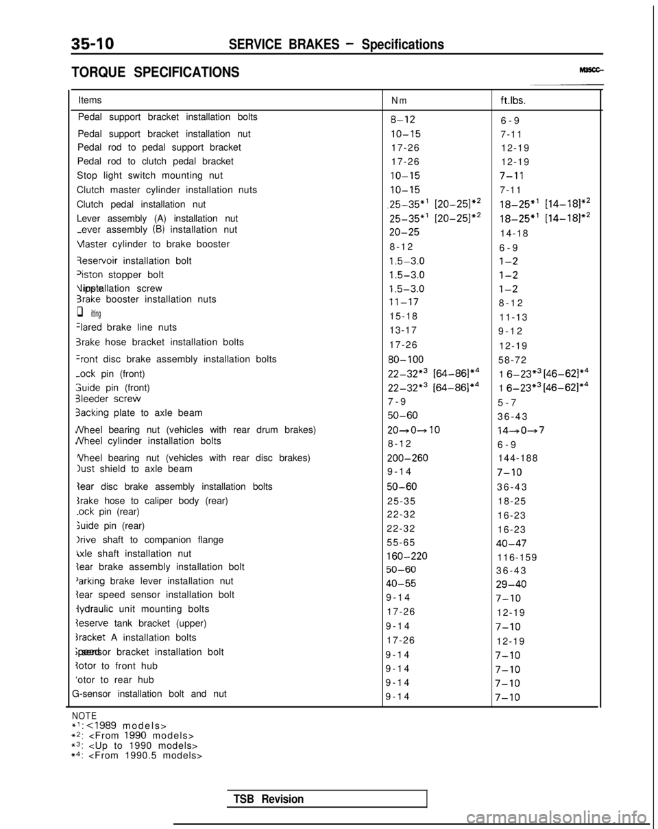
TORQUE SPECIFICATIONS
Items
Pedal support bracket installation bolts
Pedal support bracket installation nut
Pedal rod to pedal support bracket
Pedal rod to clutch pedal bracket
Stop light switch mounting nut
Clutch master cylinder installation nuts
Clutch pedal installation nut
Lever assembly (A) installation nut
-ever assembly (B) installation nut Vlaster
cylinder to brake booster qeservoir
installation bolt
‘iston stopper bolt Vipple installation screw
3rake booster installation nuts
q itting
Ilared brake line nuts
3rake hose bracket installation bolts
+ont disc brake assembly installation bolts
-ock
pin (front) 3uide
pin (front)
31eeder screw
3acking plate to axle beam
JVheel bearing nut (vehicles with rear drum brakes)
JVheel cylinder installation bolts Yheel
bearing nut (vehicles with rear disc brakes)
just shield to axle beam
Iear disc brake assembly installation bolts
srake hose to caliper body (rear)
.ock pin (rear)
&ride pin (rear)
Irive shaft to companion flange
\xle shaft installation nut
Ieserve tank bracket (upper)
bracket A installation bolts ;peed sensor bracket installation bolt
totor to front hub
‘otor to rear hub
G-sensor installation bolt and nut
NOTE*I:
~2:
Nmft.lbs.
8-126-
9
IO-157-11
17-26 12-19
17-26 12-19
IO-157-l 1
IO-157-11
,25-35”’ [20-251*218-25”’ [14-181*2
25-35*’ [20-251*218-25*’
[14-181*2
20-2514-18
8-1
2
6-9
1.5-3.0l-2
1.5-3.0l-2
1.5-3.0l-2
11-178-1
2
15-18 11-13
13-17 9-12
17-26 12-19
80-10058-72
22-32*3 [64-86]*41 6-23*3 [46-621*4
22-32*3 [64-86]*41 6-23*3 [46-62]*4
7-
9
5-7
50-6036-4
3
20~0~1014-047
8-1
2
6-9 ZOO-260
144-188
9-14
7-10
50-6036-4
3
25-35 18-25
22-32 16-23
22-32 16-23
55-65
40-47
160-220116-159
50-6036-4
3
40-5529-40
9-1
4
7-10
17-26
12-19
9-1
4
7-10
17-26
12-19
9-1
4
7-10
9-1
4
7-10
9-1
4
7-10
9-1
4
7-10
TSB Revision
Page 1136 of 1273
SERVICE BRAKES - Anti-lock Braking System Troubleshooting35-15
ANTI-LOCK BRAKING SYSTEM
TROUBLESHOOTINGM35EElAE
PARTICULAR CHARACTERISTICS OF
THE ANTI-LOCK BRAKING SYSTEM
Models equipped with the anti-lock braking system
(A.B.S.) may exhibit one or more of the following
characteristics from time to time, but none of these
is abnormal.
(1)
(2)
A pulsing feeling in the brake pedal, or vibration
of the body or the steering wheel, when the
anti-lock braking system is activated by sudden
braking or by braking on a slippery road surface.
Actually, this phenomenon is an indication that
the anti-lock braking system is functioning nor-
mally.
When the vehicle speed reaches approximately
6 km/h (4 mph) after the engine is started and
the vehicle starts off (for the first time), awhining motor noise may be heard from the
engine compartment if the vehicle is traveling in
a quiet place. This noise is simply the result of a
self-check being made of the anti-lock braking
system operation.
TROUBLESHOOTING METHODS
Problems related to the anti-lock braking system
(A.B.S.) can be classified into two general categor-
ies: problems in the electrical system and those in
the hydraulic system. For problems in the electrical system, the on-board
diagnostic is built into the electronic control unit
(E.C.U.) causing the A.B.S. warning light to illuminate
as a warning to the driver. In this instance, checks
can be made by using the scan tool and oscillo-
scope.
Problems in the hydraulic system (poor braking,
etc.) can be located in the same way as for ordinary
brakes. There is, however, the necessity to check to
determine whether the problem is related to ordi-
nary brake components or to the components re-
lated to the A.B.S. To make this check, use the scan
tool.
HOW TO USE THE TROUBLESHOOTING
FLOW CHART
(1) Using the flow chart, check the ABS warning
light light-up sequence. Read the diagnostic
trouble codes and check the condition of bra-
king operation.
(2) Following the check chart listed in the remedy
column, perform the checks. There are [Expla- nation] and [Hint] in each check chart. Refer to
them when troubleshooting.
NOTE
ECU: Electronic control unit
HU:Hydraulic unit
TSB Revision