Page 1030 of 1273
ACTIVE-ELECTRONIC CONTROL SUSPENSION - %ii%:justment 33B-91
Indicator lights that illuminate for 0.5
second after ECU power ON
Control mode AUTO mode indi-
cator
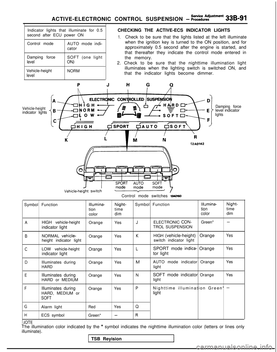
CHECKING THE ACTIVE-ECS INDICATOR LIGHTS
1.Check to be sure that the lights listed at the left illuminate
when the ignition key is turned to the ON position, and for
approximately 0.5 second after the engine is started, and
that thereafter they indicate the control mode entered in
Damping force
level
Vehicle-height
level
SOFT (one light
ON)
NORM the memory.
2. Check to be sure that the nighttime illumination light illuminates when the lighting switch is switched ON, and
that the indicator lights become dimmer.
Vehicle-heightindicator lights Damping forcelevel indicatorlights
12A0142
Control mode switches -60
Symbol FunctionIllumina-Night-
Symbol FunctionIllumina- Night-
tion time
tiontime
color
dim colordim
AHIGH vehicle-height
OrangeYesJELECTRONIC CON-Green* -
indicator lightTROL SUSPENSION
BNORMAL vehicle-OrangeYesKHIGH (vehicle-height) OrangeYes
height indicator light switch indicator light
CLOW vehicle-heightOrangeYesLSPORT mode indica- OrangeYes
indicator lighttor light
DIlluminates during
OrangeYesMAUTO mode indicator Orange Yes
HARDlight
EIlluminates duringOrange
YesNSOFT mode indicator Orange Yes
HARD or MEDIUM light
FIlluminates duringOrange
YesPNighttime illumination Green* -
HARD, MEDIUM orlight
SOFT
GAlarm lightRedYesQ
HECS symbol
Green* -R
IA-r-Cl”lCT‘he illumination color indicated by the * symbol indicates the nighttime illumination color (letters or lines on\
ly
illuminate).
TSB Reyision
Page 1031 of 1273
33B-92 ACTIVE-ELECTRONIC CONTROL SUSPENSION - ~~:%:?stment
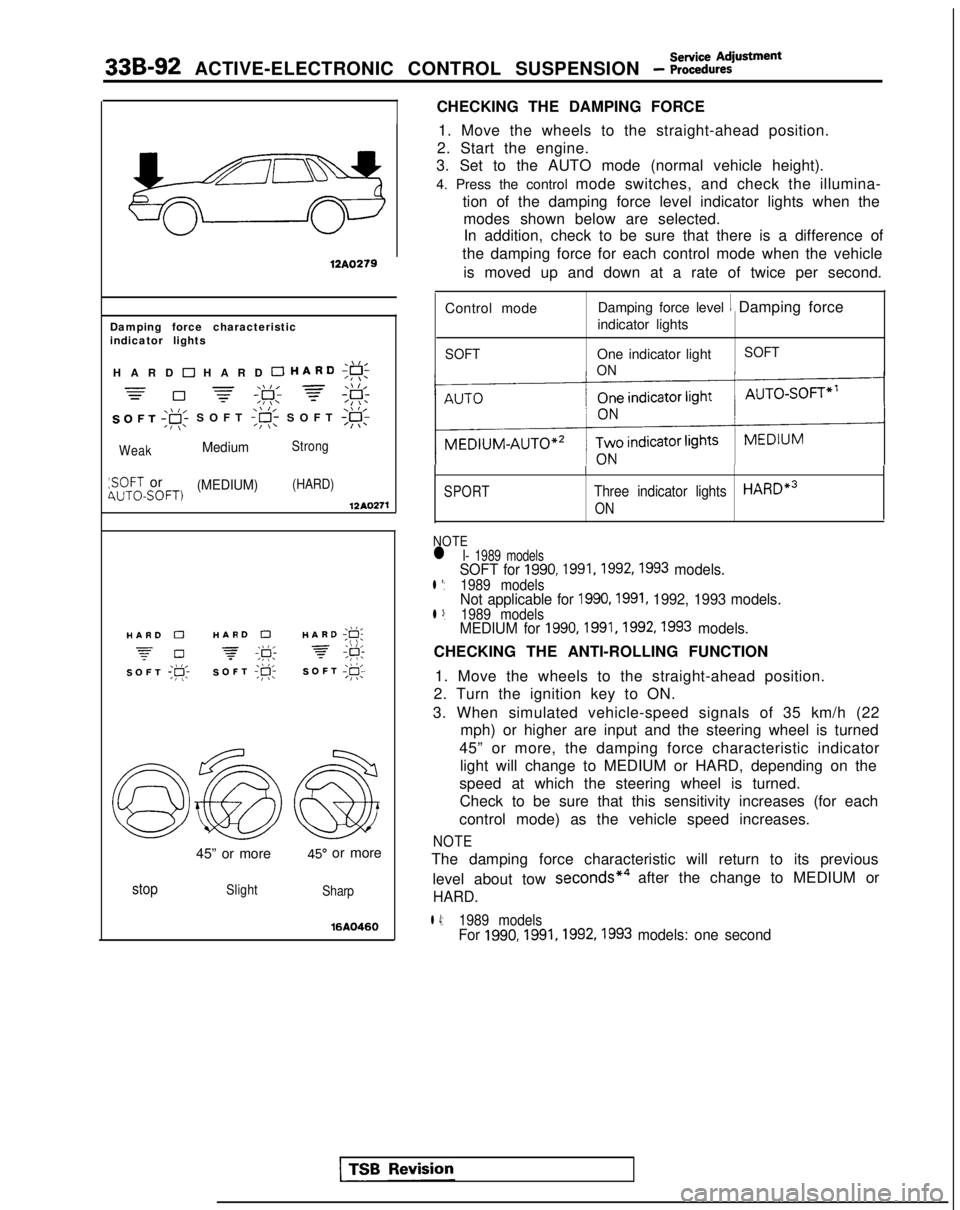
CHECKING THE DAMPING FORCE
12A0279
Damping force characteristic
indicator lights
,\,IHARD 0 HARD 0 HARD;g!;
=-\\I, =\\ l,=0 -=-,F; f;F:
SOFT ,gi SOFT
WeakMediumStrong
:SOFT or(MEDIUM)(HARD)4UTOSOFT)12AQ271
./I,HARD 0HARD 0HARD ;g;
z-0 -\k 3,\I I,SOFT ;p;SOFT ;R-SOFT I@;
45” or more45” or more
stopSlight
Sharp
16AQ460
1. Move the wheels to the straight-ahead position.
2. Start the engine.
3. Set to the AUTO mode (normal vehicle height).
4. Press the control mode switches, and check the illumina-
tion of the damping force level indicator lights when themodes shown below are selected.In addition, check to be sure that there is a difference of
the damping force for each control mode when the vehicle
is moved up and down at a rate of twice per second.
Control mode Damping force level
1 Damping force
indicator lights
SOFTOne indicator light
ON SOFT
SPORT
I
Three indicator lightsHARDe3
ON
NOTEl I- 1989 modelsSOFT for 1990,1991,1992,1993 models.l *:1989 modelsNot applicable for 1990,1991, 1992, 1993 models.l 3:1989 modelsMEDIUM for 1990,1991,1992,1993 models.
CHECKING THE ANTI-ROLLING FUNCTION
1. Move the wheels to the straight-ahead position.
2. Turn the ignition key to ON.
3. When simulated vehicle-speed signals of 35 km/h (22 mph) or higher are input and the steering wheel is turned
45” or more, the damping force characteristic indicator light will change to MEDIUM or HARD, depending on the
speed at which the steering wheel is turned. Check to be sure that this sensitivity increases (for each
control mode) as the vehicle speed increases.
NOTE
The damping force characteristic will return to its previous
level about tow seconds*4
after the change to MEDIUM or
HARD.
l 4:1989 modelsFor 1990,1991,1992,1993
models: one second
Page 1032 of 1273
Service AdjustmentACTIVE-ELECTRONIC CONTROL SUSPENSION - Procedures33B-93
\\ I/HARD ;g;
7 #
SOFT;#c
\\ I/HARD ;F;
7 ;&
SOFT;@;
I12AO399
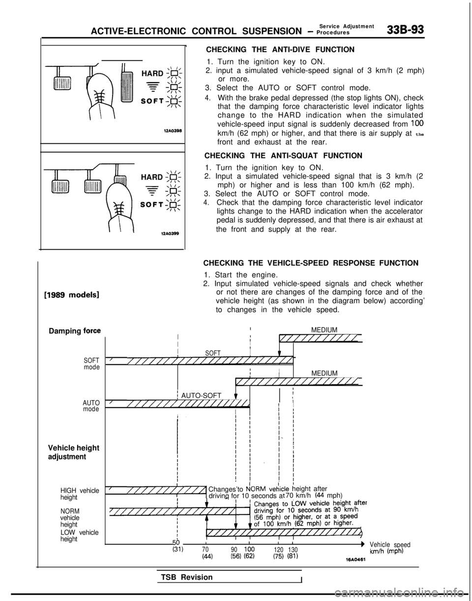
CHECKING THE ANTI-DIVE FUNCTION1. Turn the ignition key to ON.
2. input a simulated vehicle-speed signal of 3 km/h (2 mph) or more.
3. Select the AUTO or SOFT control mode.
4.With the brake pedal depressed (the stop lights ON), check
that the damping force characteristic level indicator lights
change to the HARD indication when the simulated
vehicle-speed input signal is suddenly decreased from
100
km/h (62 mph) or higher, and that there is air supply at the
front and exhaust at the rear.
CHECKING THE ANTI-SQUAT FUNCTION 1. Turn the ignition key to ON.
2. Input a simulated vehicle-speed signal that is 3 km/h (2
mph) or higher and is less than 100 km/h (62 mph).
3. Select the AUTO or SOFT control mode.
4.Check that the damping force characteristic level indicator lights change to the HARD indication when the accelerator
pedal is suddenly depressed, and that there is air exhaust at
the front and supply at the rear. [1989
models1
Damping force
SOFTmode
AUTO mode
Vehicle height
adjustment
HIGH vehicle
height
NORMvehicle
height
LOW vehicle
height
CHECKING THE VEHICLE-SPEED RESPONSE FUNCTION
1. Start the engine.
2. Input simulated vehicle-speed signals and check whether or not there are changes of the damping force and of the
vehicle height (as shown in the diagram below) according’
to changes in the vehicle speed.
IMEDIUMI1I//////////IIIII8SOFTI////////////////////////IIIIMEDIUMI////////////////
j AUTO-SOFT I ;I ,////////////////i//dI I
I
Ij I
I/Changes’to P!ORMveiic“““““1 drivinq for 10 seconds a:le height after t 70 km/h (44 mph)
III
I 1g,70
90100 120130bVehicle
speed
(44(56) (62)(75) (81)km/h (mph)1610461
TSB RevisionI
Page 1046 of 1273
ACTIVE-ELECTRONIC CONTROL SUSPENSION - Stabilizer Bar33Bl107
UL Wire/
12A0283SERVICE POINTS OF REMOVAL
2. REMOVAL OF FRONT EXHAUST PIPE
After disconnection of the front exhaust pipe assembly and
the exhaust manifold, use wire, etc. to hang the front
exhaust pipe down.
Caution Do not bend the flexible joint more than shown in the
figure, because there is danger the inside may be
damaged if it is bent too much.
7. REMOVAL OF STABILIZER LINK MOUNTING NUTS Using a wrench or similar tool to secure the ball studs at
both ends of the stabilizer link, remove the mounting nuts.
12. REMOVAL OF STABILIZER
BAR
(1) Disconnect either the left or right lower arm from the crossmember, and slightly lower the installation part.
(2) Pull out both ends of the stabilizer bar to the rear of the drive shaft.
NOTE
First pass the end of the stabilizer bar (at the side at
which the lower arm was not lowered) under the drive shaft, and then pull out toward the rear.
Page 1055 of 1273
33B-116 ACTIVE-ELECTRONIC CONTROL SUSPENSION - z%rension
‘3.
Apply rubber grease
1Paint
Install at the shockabsorber side.
12A0327
19. REMOVAL OF SHOCK ABSORBER UPPER MOUNTING
NUTS/PO. TRAILING ARM MOUNTING
BOLTS/Zl.
REAR SUSPENSION ASSEMBLY
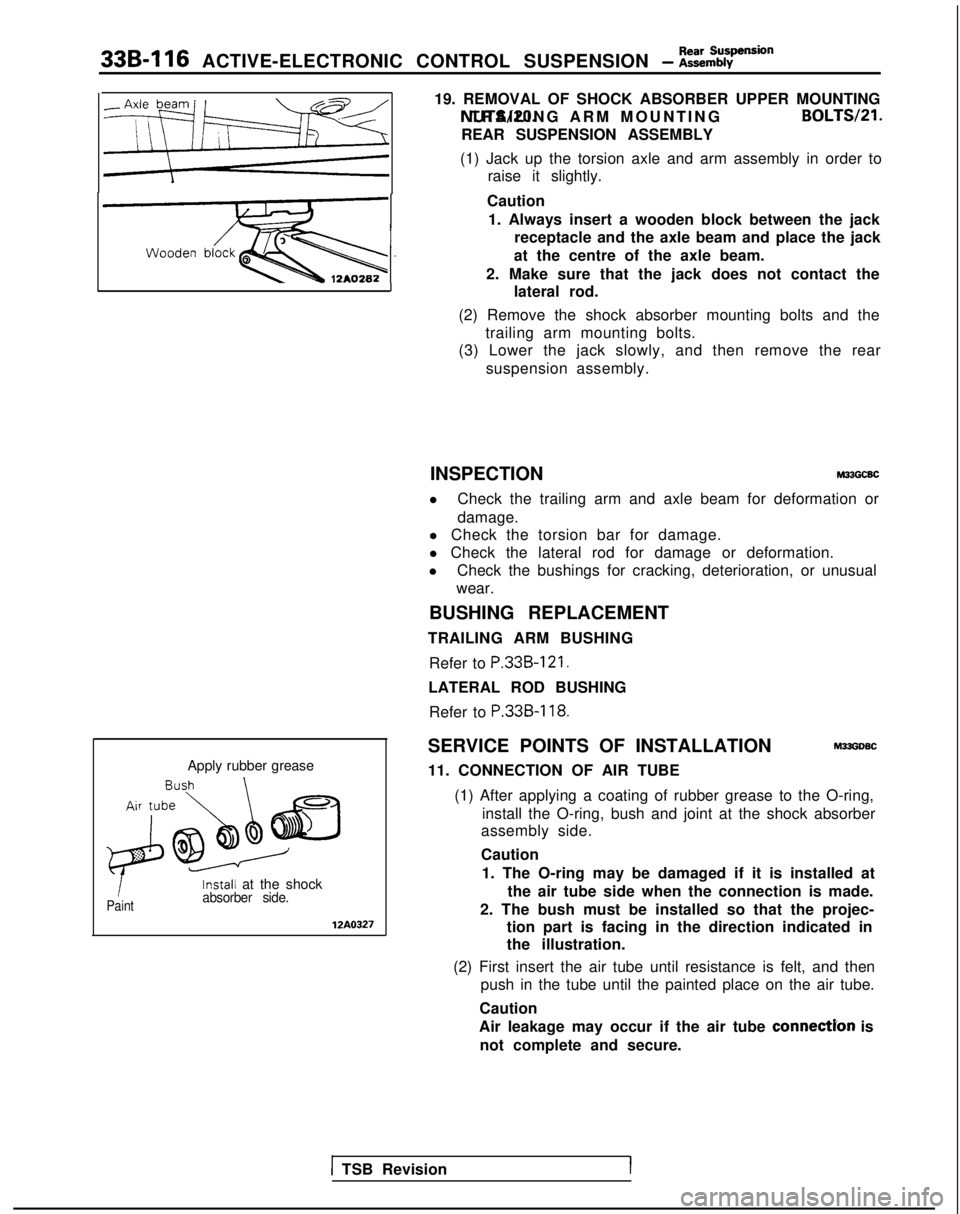
(1) Jack up the torsion axle and arm assembly in order to raise it slightly.
Caution 1. Always insert a wooden block between the jack receptacle and the axle beam and place the jack
at the centre of the axle beam.
2. Make sure that the jack does not contact the lateral rod.
(2) Remove the shock absorber mounting bolts and the trailing arm mounting bolts.
(3) Lower the jack slowly, and then remove the rear
suspension assembly.
INSPECTION
M33GCBC
l Check the trailing arm and axle beam for deformation or
damage.
l Check the torsion bar for damage.
l Check the lateral rod for damage or deformation.
l Check the bushings for cracking, deterioration, or unusual
wear.
BUSHING REPLACEMENT
TRAILING ARM BUSHING
Refer to
P.33B-121.
LATERAL ROD BUSHINGRefer to
P.33B-118.
SERVICE POINTS OF INSTALLATIONM33GDSC
11. CONNECTION OF AIR TUBE
(1) After applying a coating of rubber grease to the O-ring, install the O-ring, bush and joint at the shock absorber
assembly side.
Caution
1. The O-ring may be damaged if it is installed at the air tube side when the connection is made.
2. The bush must be installed so that the projec- tion part is facing in the direction indicated in
the illustration.
(2) First insert the air tube until resistance is felt, and then push in the tube until the painted place on the air tube.
Caution
Air leakage may occur if the air tube
connectYon is
not complete and secure.
1 TSB RevisionI
Page 1059 of 1273
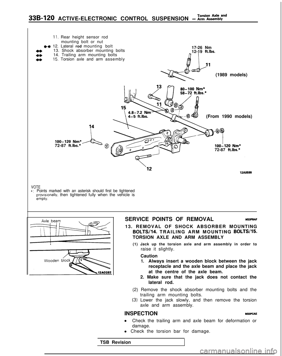
33B-120 ACTIVE-ELECTRONIC CONTROL SUSPENSION - Z%iZky8”d
11. Rear height sensor rodmounting bolt or nut
~~ 12. Lateral rod mounting bolt
13. Shock absorber mounting bolts 17-26 Nm
a*12-19 ftlbs.*I)14. Trailing arm mounting bolts
4*15. Torsion axle and arm assembl
y
(1989 models)
(From 1990 models)
loo-120 Nm*
72-87 ft.lbs.*A‘g0loo-120 Nm*
72-87 ft.lbs.*
VOTE*:Points marked with an asterisk should first be tightenedprovrslonally. then tightened fully when the vehicle isempty.
SERVICE POINTS OF REMOVALM33PaAF
13. REMOVAL OF SHOCK ABSORBER MOUNTING BOLTW14.
TRAILING ARM MOUNTING BOLTW15.
TORSION AXLE AND ARM ASSEMBLY
(1) Jack up the torsion axle and arm assembly in order to raise it slightly.
Caution
1.Always insert a wooden block between the jack receptacle and the axle beam and place the jack
at the centre of the axle beam.
2. Make sure that the jack does not contact the lateral rod.
(2) Remove the shock absorber mounting bolts and the trailing arm mounting bolts.
(3) Lower the jack slowly, and then remove the torsionaxle and arm assembly.
INSPECTION
M22PcAE
l Check the trailing arm and axle beam for deformation or
damage.
l Check the torsion bar for damage.
TSB Revision
Page 1079 of 1273
338-140 ACTIVE-ELECTRONIC CONTROL SUSPENSION - t:%%%=mb’y’
INDICATOR ASSEMBLY
SERVICE POINTS OF REMOVAL(1) Using a plastic trim tool, remove the indicator assembly from the instrument panel.
(2) Disconnect the connector and remove the indicator assembly.
INSPECTION
(1) Indicator light does not light (the circuit, light bulb, or LED have failed).
NOTE
Operate the ECS and check to see that the light bulbs and
LED light.
(2) Do the lights loose intensity when the lighting switch is placed at
50 0:and$D . For procedures for other
inspections, refer to the troubleshooting section.
CONTROL UNIT
SERVICE POINTS OF REMOVAL
(1) Remove the trunk side trim. (Refer to GROUP
52-Trims.)
(2) Remove the installation bolts and connectors, and then
remove the control unit.
INSPECTION Referring to the troubleshooting section, check whether there
is terminal voltage.
TSB Revision
Page 1083 of 1273
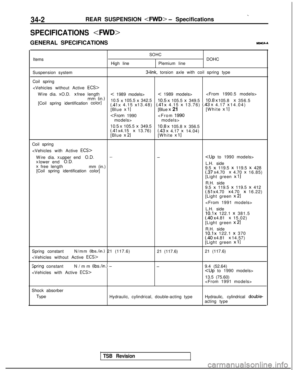
34-2REAR SUSPENSION - Specifications
SPECIFICATIONS
GENERAL SPECIFICATIONS
M3CA-A
Items
Suspension system
Coil spring High lineSOHCDOHC
Plemium line 3-link.
torsion axle with coil spring type
Wire dia. x O.D. x free length
< 1989 models>< 1989 models>
mm
h-d
[Coil spring identification color]
10.5 x
105.5 x
342.5
10.5 x
105.5 x
349.510.8 x 105.8 x
356.5(.41 x
4.15 x 13.48) (.41 x
4.15 x
13.76) (.43 x 4.17 x 14.04)
[Blue x 11[Blue x
21 [White x
II
models>
10.5 x
105.5 x
349.510.8 x
105.8 x
356.5 (41
x 4.15 x
13.76)(.43 x
4.17 x
14.04)
[Blue x 21[White x 11
Coil spring
Wire dia. x upper end
O.D.--
x lower end
O.D.L.H. side
x
free length
mm (in.)
9.5 x 119.5 x
119.5 x
428
[Coil spring identification color](.37 x 4.70 x 4.70 x
16.85)
[Light green x
II
R.H. side
9.5 x 119.5 x
119.5 x 412(.51 x 4.70 x 4.70 x
16.22)
[Light green x
21
L.H. side
10.1 x
122.1 x
381.5(.40 x 4.81 x 15.02)
[Light green x
21
R.H. side10.1 x
122.1 x
370 (.40 x 4.81 x 14.57)
[Light green x
11
Spring constant N/mm (Ibs./in.) 21 (117.6)
21 (117.6)
21 (117.6)
Spring constant
N/mm (Ibs./in.) -
-9.4 (52.64)
13.5 (75.60)
Shock absorber Type
Hydraulic, cylindrical, double-acting type
Hydraulic, cylindrical double-
acting type
TSB Revision