1988 PONTIAC FIERO oil temperature
[x] Cancel search: oil temperaturePage 576 of 1825
DRIVEABILIW AND EMISSIONS - 5.OL (VIN E) 6E2-62-1
SECTION C2
FUEL CONTROL SYSTEM
TBI MODEL 228
CONTENTS
GENERAL DESCRIPTION . . . . . . . . . . . . . . . C2-1
PURPOSE ......................... C2-1
MODES OF OPERATION . . . . . . . . . . . . . . C2-1
Starting Mode . . . . . . . . . . . . . . . . . . . C2-1
Clear Flood Mode . . . . . . . . . . . . . . . . C2-2
RunMode . . . . . . . . . . . . . . . . . . . . . . C2-2
Open Loop . . . . . . . . . . . . . . . . . . . . . . C2-2
Closed Loop . . . . . . . . . . . . . . . . . . . . . C2-2
Acceleration Mode . . . . . . . . . . . . . . . C2-2
Deceleration Mode . . . . . . . . . . . . . . . C2-2
Battery Correction Mode . . . . . . . . . . . C2-2
Fuel Cut Off Mode . . . . . . . . . . . . . . . . C2-2
FUEL CONTROL SYSTEM COMPONENTS
. . . C2-2
BASIC SYSTEM OPERATION . . . . . . . . . . . C2-3
THROTTLE BODY INJECTION (TBI) UNIT. . . C2-3
Fuel Injectors . . . . . . . . . . . . . . . . . . . . C2-3
Pressure Regulator . . . . . . . . . . . . . . . C2-3
ldle Air Control (IAC) Valve . . . . . . . . . . C2-4
Throttle Position Sensor (TPS) . . . . . . . . C2-4
FUEL PUMP.. . . . . . . . . . . . . . . . . . . . . . . C2-5
FUEL PUMP ELECTRICAL CIRCUIT . . . . . . . C2-5
DIAGNOSIS . . . . . . . . . . . . . . . . . . . . . . * C2-5
FUEL CONTROL . . . . . . . . . . . . . . . . . . . . C2-5
GENERAL DESCRIPTION
PURPOSE
The basic function of the fuel control system is to
control fuel delivery to the engine. Fuel is delivered to
the engine by
a throttle body injection ('FBI) unit.
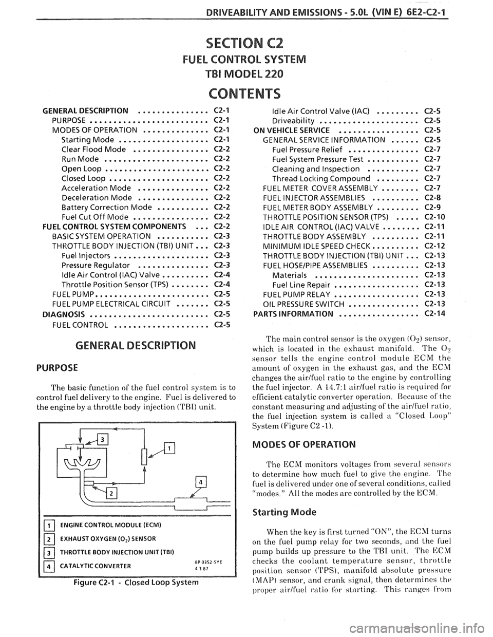
ENGINE CONTROL MODULE (ECM)
EXHAUST OXYGEN (0,) SENSOR
I 1 THROTTLE BODY INJECTION UNIT (TBI)
CATALYTIC CONVERTER
8P 0352 SYE a 3 81
Figure C2-1 - Closed Loop System
ldle Air Control Valve (IAC) . . . . . . . . . C2-5
Driveability . . . . . . . . . . . . . . . . . . . .. C2-5
ON VEHICLE SERVICE
. . . . . . . . . . . . . . . . . C2-5
GENERAL SERVICE INFORMATION . . . . . . C2-5
Fuel Pressure Relief . . . . . . . . . . . . . . . C2-7
Fuel System Pressure Test . . . . . . . . . . . C2-7
Cleaning and Inspection . . . . . . . . . . . C2-7
Thread Locking Compound . . . . . . . . . C2-7
FUEL METER COVER ASSEMBLY . . . . . . . . C2-7
FUEL INJECTOR ASSEMBLIES . . . . . . . . . . C2-8
FUEL METER BODY ASSEMBLY . . . . . . . . . C2-9
THROTTLE POSITION SENSOR (TPS) . . . . . C2-10
IDLE AIR CONTROL (IAC) VALVE . . . . . . . . C2-11
THROTTLEBODYASSEMBLY .......... C2-11
MINIMUM IDLE SPEED CHECK.. . . . . . . . . C2-12
THROTTLE BODY INJECTION (TBI) UNIT.. . C2-I3
FUEL HOSEIPIPE ASSEMBLIES . . . . . . . . . . C2-13
Materials . . . . . . . . . . . . . . . . . . . . . . C2-13
Fuel Line Repair . . . . . . . . . . . . . . . . . . C2-13
FUEL PUMP RELAY . . . . . . . . . . . . . . . . . . C2-13
OIL PRESSURE SWITCH . . . . . . . . . . . . . . . C2-13
PARTS INFORMATION
. . . . . . . . . . . . . . . . . C2-14
The main control sensor is the oxygen (02) sensor,
which is located in the exhaust manifold. The
O?
sensor tells
the engine control module ECM the
amount of osygen in the exhttust gas, and the ECM
changes the airtfuel ratio to the engine by controlling
the fuel injector.
A 14.7: 1 aidfuel ratio is required for
efficient catalytic converter operation. Because of the
constant measuring and adjusting of the
airlfuel ratio,
the fuel injection system is called a "Closed
IAoopP
System (Figure C2 -1).
MODES OF OPERATION
The ECM monitors voltages from several sensors
to determine how
much fuel to give the engine. The
fuel is delivered under one of several conditions, called
"modes." All the modes are controlled by the ECM.
Starting Mode
When the key is first turned "ON", the ECM turns
on the fuel pump relay for two seconds,
i~nd the l'uel
pump builds up pressure to the TRI unit. The ECM
checks the coolant
temperature sensor, throttle
position sensor
('UPS), manifold absolute pressure
(MAP) sensor, and crank signal, then determines the
proper airtfuel ratio tbr starting. This ranges from
Page 600 of 1825
DRIVEABILITY AND EMISSIONS 5.QL (VIN E) 6Ef-C4-1
SECTION C4
IGNITION SYSTEM 1 (EST)
CQN"FEB\BTO
GENERAL DESCRIPTION ............... C4-1
PURPOSE ........................ C4-1
OPERATION
............*......... C4-1
DIAGNOSIS
........................ C4-1
..... RESULTS OF INCORRECT EST OPER. C4-1
HOW CODE 42 IS DETERMINED ....... C4-2
GENERAL DESCRIPTION
PURPOSE
The High Energy Ignition (HE11 system controls
fuel combustion by providing a spark to ignite the
compressed
aidfuel mixture at the correct time. To
provide improved engine performance, fuel economy,
and control of exhaust emissions, the ECM controls
distributor spark advance (timing) with the Electronic
Spark Timing (EST) system.
Only the Electronic Spark 'Timing (EST) system
will be described here. Additional information on the
HE1 system is found in Section 6D.
OPERATION
The standard high energy ignition (HEI) system
(described in Section 6D) has a modified distributor
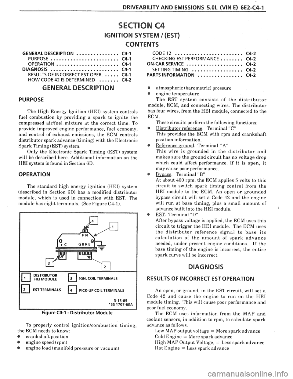
module, which is used in connection with EST.
The
module has eight terminals. (See Figure C4-1).
IGN. COIL TERMINALS
EST TERMINALS PICK-UP
COIL TERMINALS
Figure C4-1 - Distributor Module
To properly control ignition/combustion timing,
the ECM needs to know:
@ crankshaft position
@ engine speed (rpm)
@ engine load (manifold pressure or vacuum)
CODE12 ........................ C4-2
CHECKING EST PERFORMANCE ........ C4-2
ON-CAR SERVICE ...a.e.............. C4-2
SETTING TIMING
.................. C4-2
PARTSINFORMATION ................ C4-2
@ atmospheric (barometric) pressure
@ engine temperature
The EST system consists of the distributor
module, ECM, and connecting wires. The distributor
has four wires, from the
HE1 module, connected to the
ECM.
These circuits perform the following functions:
@ Distributor reference. Terminal "C"
This provides the ECM with rpm and crankshaft
position information.
@ Reference ground. Terminal "A"
'I'his wire is grounded in the distributor and
makes sure the ground circuit has no voltage drop
which could affect performance. If it is open, it
may cause poor performance.
@ Bypass. Terminal "BJ'
At about 400 rpm, the ECM applies 5 volts to this
circuit to switch spark timing control
from the
HE1 module to the ECM. An open or grounded
bypass circuit will set a Code 42 and the engine
will run at base timing, plus a small
amount of
advance built into the
HE1 module.
@ EST. 'Terminal "D"
After bypass voltage is applied, the ECM uses this
circuit to trigger the
HE1 module. The ECM uses
the distributor reference signal to base its
calculation of the amount of spark advance
needed, under present engine conditions.
Lf the
base timing of the engine is incorrect, the entire
spark curve will be incorrect.
RESULTS OF INCORRECT EST OPERATION
An open, or ground, in the EST circuit, will set a
Code 42 and cause the engine to run on the HE1
module timing. 'I'his will cause poor performance and
poor fuel economy.
'I'he ECM uses information from the MAP and
coolant sensors, in addition to rpm, to calculate spark
advance as follows.
I,ow MAP output voltage = More spark advance
Cold Engine
= More spark advance
High
MAP Output Voltage, = Less spark advance
IIot 12ngine = 1,ess spark advance
Page 629 of 1825

6EZ-C8-4 DRIVEABILITY AND EMISSIONS - 5.OL (VIN E)
I5 WAY (FRONT VIEW)
SPEED INPUT
4rH GEAR SIGNAL
422 TANIBLK
ALDL CONNECTOR
CHART C-8A
TRANSMISSION CONVERTER CLUTCH (TCC)
ELECTRICAL DIAGNOSIS
(Page 1 of 2)
5.OL (VIN E) "F" "SERIES (TBI)
Circuit Description:
The purpose of the automatic transmission torque converter clutch is to eliminate the power loss of the
torque converter, when the vehicle is in a cruise condition. This allows the convenience of the automatic
transmission and the fuel economy of a manual transmission.
Fused battery ignition is supplied to the TCC solenoid through the brake switch. the ECM will engage
TCC
by grounding CKT 422 to energize the solenoid.
TCC will engage when:
- Vehicle speed above 24 mph - Engine at normal operating temperature (above 70°C, 156°F)
- Throttle position sensor output not changing, indicating a steady road speed
- Brake switch closed
Test Description: Numbers below refer to circled solenoids
and relays before installing a
numbers on the diagnostic chart. replacement ECM. Replace
any solenoid or relay
1. Confirms 12 volt supply as well as continuity of that
measures less than 20 ohms.
TCC circuit.
2. Grounding the diagnostic terminal with engine Diagnostic Aids:
"OFF", should energize the capability of the ECM An
engine coolant thermostat that is stuck open or
to control the solenoid. opens
at too low a temperature, may result in an
3. Solenoid coil resistance must measure more than inoperative TCC.
20 ohms. Less resistance will cause early failure
of the ECM
drive^.". Using an ohmmeter, check
the solenoid coil resistance of
all ECM controlled
Page 655 of 1825
6E3-A-2 2.88, (VIM S) DRIVEABILITY AND EMISSIONS
'Fa SERIES
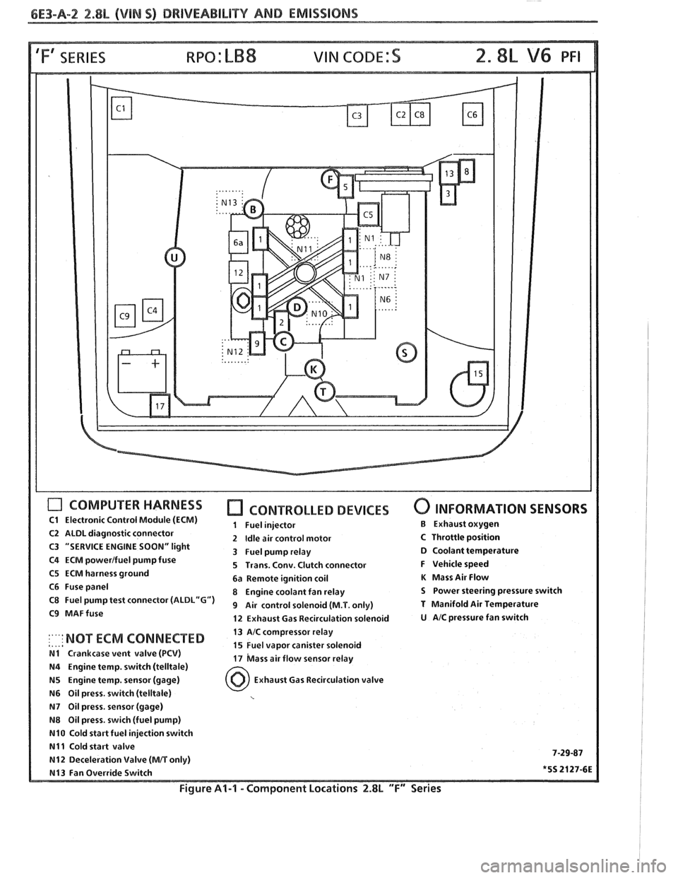
COMPUTER HARNESS
C1 Electronic Control Module (ECM)
C2 ALDL diagnostic connector
C3 "SERVICE ENGINE
SOON" light
C4 ECM powerlfuel pump fuse
C5 ECM harness ground
C6 Fuse panel
C8 Fuel pump test connector
(ALDL"G")
C9 MAFfuse
CONTROLLED DEVICES
1 Fuel injector
2
Idle air control motor
3 Fuel pump relay
5 Trans. Conv. Clutch connector
6a Remote ignition coil
8 Engine coolant fan relay
9 Air control solenoid (M.T. only)
12 Exhaust Gas Recirculation solenoid
0 INFORMATION SENSORS
B Exhaust oxygen
C Throttle position D Coolant temperature
F Vehicle speed
K Mass Air Flow
S Power steering pressure switch
T Manifold Air Temperature
U AIC pressure fan switch
13 AIC compressor relay
,..,a :'"' NOT ECM 'ONNECTED 15 Fuel vapor canister solenoid N1 Crankcase vent valve (PCV) 17 bass air flow sensor relay N4 Engine temp. switch (telltale)
N5 Engine temp. sensor (gage) Exhaust Gas Recirculation valve
N6 Oil press. switch (telltale)
N7 Oil press, sensor (gage)
N8 Oil press. swich (fuel pump)
N10 Cold start fuel injection switch
N11 Cold start valve 7-29-87 N12 Deceleration Valve (MIT only)
N13 Fan Override Switch *5S 2127-6E
Figure Al-l - Component Locations 2.8L "F" Series
Page 711 of 1825
6E3-B-2 2.8L (VIN 5) DRIVEABILITY AND EMISSIONS
Problem may or may not turn "ON" the "Service Engine SoonJ' light, or store a code.
DO NOT use the trouble code charts in Section
"A" for intermittent problems. The fault must be
present to locate the problem. If a fault is
intermittent, use of trouble code charts may result
in replacement of good parts.
@ Most intermittent problems are caused by
faulty electrical connections or wiring. Perform
careful check as described at start of Section
"B". Check for:
@ Poor mating of the connector halves, or
terminals not fully seated in the connector
body (backed out).
@ Improperly formed or damaged terminals.
All connector terminals in problem circuit
should be carefully reformed to increase
contact tension.
@ Poor terminal to wire connection. This
requires removing the terminal from the
connector body to check. See "Introduction"
to Section
"6E".
@ If a visual check does not find the cause of the
problem, the car can be driven with a voltmeter
connected to a suspected circuit. A "Scan" tool
can also be used for monitoring input signals to
the ECM to help detect intermittent conditions.
An abnormal voltage, or "Scan" reading, when
the problem occurs, indicates the problem may
be in that circuit. If the wiring and connectors
check OK and a trouble code was stored for a
circuit having a sensor, except for Codes
43, 44,
and 45, substitute a known good sensor and
recheck. An
intermittent "Service Engine Soon" light
with no stored code may be caused by:
@ Ignition coil shorted to ground and arcing at
spark plug wires or plugs.
@ "Service Engine Soon" light wire to ECM
shorted to ground. (CKT 419).
@ Diagnostic "Test" terminal wire to ECM,
shorted to
ground.(CKT 451)
@ ECM power grounds. See ECM wiring
diagrams.
@ Loss of trouble code memory. To check,
disconnect TPS and idle engine until "Service
Engine Soon" light comes "ON". Code
22 should
be stored, and kept in memory when ignition is
turned "OFF". If not, the ECM is faulty.
@ Check for an electrical system interference
caused by a defective relay, ECM driven
solenoid, or switch. They can cause
a sharp
electrical surge. Normally, the problem will
occur when the faulty component is operated.
@ Check for improper installation of electrical
options, such as lights, 2-way radios, etc.
@ EST wires should be kept away from spark plug
wires, distributor wires, distributor housing,
coil, and generator. Wire from ECM to
distributor (CKT
453) should be a good
connection.
@ Check for open diode across A/C compressor
clutch, and for other open diodes (see wiring
diagrams).
HARD START
Definition: Engine cranks OK, but does not start for a long
time. Does eventually run, or may start hut immediately dies.
@ Perform careful check as described at start of -
Section "B".
@ Make sure driver is using correct starting
procedure.
@ CHECK:
- TPS for sticking or binding or a high TPS
voltage with the throttle closed (should read
less than
,700 volts).
- High resistance in coolant sensor circuit or
sensor itself. See Code 15 chart or with
a.
"Scan" tool compare coolant temperature with
ambient temperature on
a cold engine. 8
- Fuel pressure CHART A-7. Water contaminated
fuel.
EGR operation. Be sure valve seats properly and
is not staying open. See CHART C-7.
Both injector fuses (visually inspect).
Ignition system
- Check distributor for:
Proper output with ST-125.
Worn shaft.
Bare and shorted wires.
Pickup coil resistance and connections.
Loose ignition coil ground.
Moisture in distributor cap.
If problem exists in cold weather, check cold start
valve. See CHART A-9.
Page 755 of 1825
6E3-C2-20 2.8L (VIN S) DRIVEABILITY AND EMISSIONS
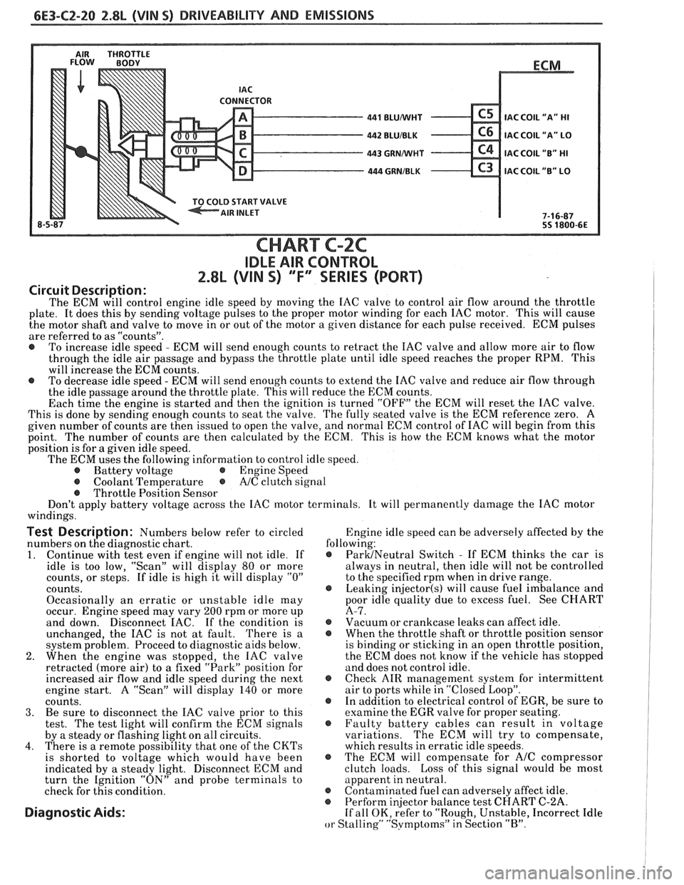
AIR THROTTLE FLOW BODY
LD START VALVE
8-5 BLUNVHT
BLUIBLK
GRMNVHT
. GRNIBLK
ECM
.
IAC COIL
"A" HI
IAC COIL "A" LO
IAC COIL "B" HI
C3 IAC COIL "B" LO
7-1 6-87
55 1800-6E
CHART C-2C
IDLE AIR CONTROL
2.8L (VIN S) ""F-SERIES (PORT)
Circuit Description:
The ECM will control engine idle speed by moving the IAC valve to control air flow around the throttle
plate. It does this by sending voltage pulses to the proper motor winding for each IAC motor. This will cause
the motor shaft and valve to move in or out of the motor a given distance for each pulse received. ECM pulses
are referred to as "counts".
@ To increase idle speed - ECM will send enough counts to retract the IAC valve and allow more air to flow
through the idle air passage and bypass the throttle plate until idle speed reaches the proper RPM. This
will increase the ECM counts.
@ To decrease idle speed - ECM will send enough counts to extend the IAC valve and reduce air flow through
the idle passage around the throttle plate. This will reduce the ECM counts.
Each time the engine is started and then the ignition is turned "OFF" the ECM will reset the IAC valve.
This is done by sending enough counts to seat the valve. The fully seated valve is the ECM reference zero. A
given number of counts are then issued to open the valve, and normal ECM control of IAC will begin from this
point. The
number of counts are then calculated by the ECM. This is how the ECM knows what the motor
position is for
a given idle speed.
The ECM uses the following information to control idle speed.
@ Battery voltage @ Engine Speed
@ Coolant Temperature @ A/C clutch signal
@ Throttle Position Sensor
Don't apply battery voltage across the IAC motor terminals. It will permanently damage the IAC motor
windings.
Test Description: Numbers below refer to circled Engine
idle speed can be adversely affected by the
numbers on the diagnostic chart. following:
1. Continue
with test even if engine will not idle. If @ ParUNeutral Switch - If ECM thinks the car is
idle is too low, "Scan" will display
80 or more always
in neutral, then idle will not be controlled
counts, or steps. If idle is high it will display
"0" to the specified rpm when in drive range.
counts.
@ Leaking injector(s) will cause fuel imbalance and
Occasionally an erratic or unstable idle may poor
idle quality due to excess fuel. See CHART
occur. Engine speed may vary
200 rpm or more up A-7.
and down. Disconnect
EAC. If the condition is @ Vacuum or crankcase leaks can affect idle.
unchanged, the IAC is not at fault. There is
a @ When the throttle shaft or throttle position sensor
system problem. Proceed to diagnostic aids below. is
binding or sticking in an open throttle position,
2. When the engine was stopped, the IAC valve the
ECM does not know if the vehicle has stopped
retracted (more air) to a fixed "Park" position for and does not control idle.
increased air flow and idle speed during the next
@ Check AIR management system for intermittent
engine start. A "Scan" will display
140 or more air
to ports while in "Closed Loop".
counts. @ In addition to electrical control of EGR, be sure to
3. Be sure to disconnect the IAC valve prior to this examine the
EGR valve for proper seating.
test. The test light will confirm the ECM signals @ Faulty battery cables can result in voltage
by a steady or flashing light on all circuits. variations. The
ECM will try to compensate,
4. There is a remote possibility that one of the CKTs which results in erratic idle speeds.
is shorted to voltage which would have been @ The ECM will compensate for A/C compressor
indicated by a steady light. Disconnect ECM and clutch
loads. Loss of this signal would be most
turn the Ignition "ON" and probe terminals to apparent
in neutral.
check for this condition.
@ Contaminated fuel can adversely affect idle. @ Perform in
or Stalling" "Svmptoms" in Section "B".
Page 771 of 1825
6E3-C6-2 2.8L (WIN 5) DRIVEABILITY AND EMISSIONS
When the solenoid is de-energized, the pressurized
air from the air pump is allowed to enter the decel
timing chamber. This places sufficient pressure on
the metering valve diaphragm to overcome spring
tension, closing the
valve,causing air to divert to the
silencer.
At higher engine speeds, excess air is exhausted to
the silencer through the pressure relief valve. (Figure
C6-1)
Deceleration Valve
To help prevent backfiring during high vacuum
conditions a deceleration (gulp) valve is used to allow
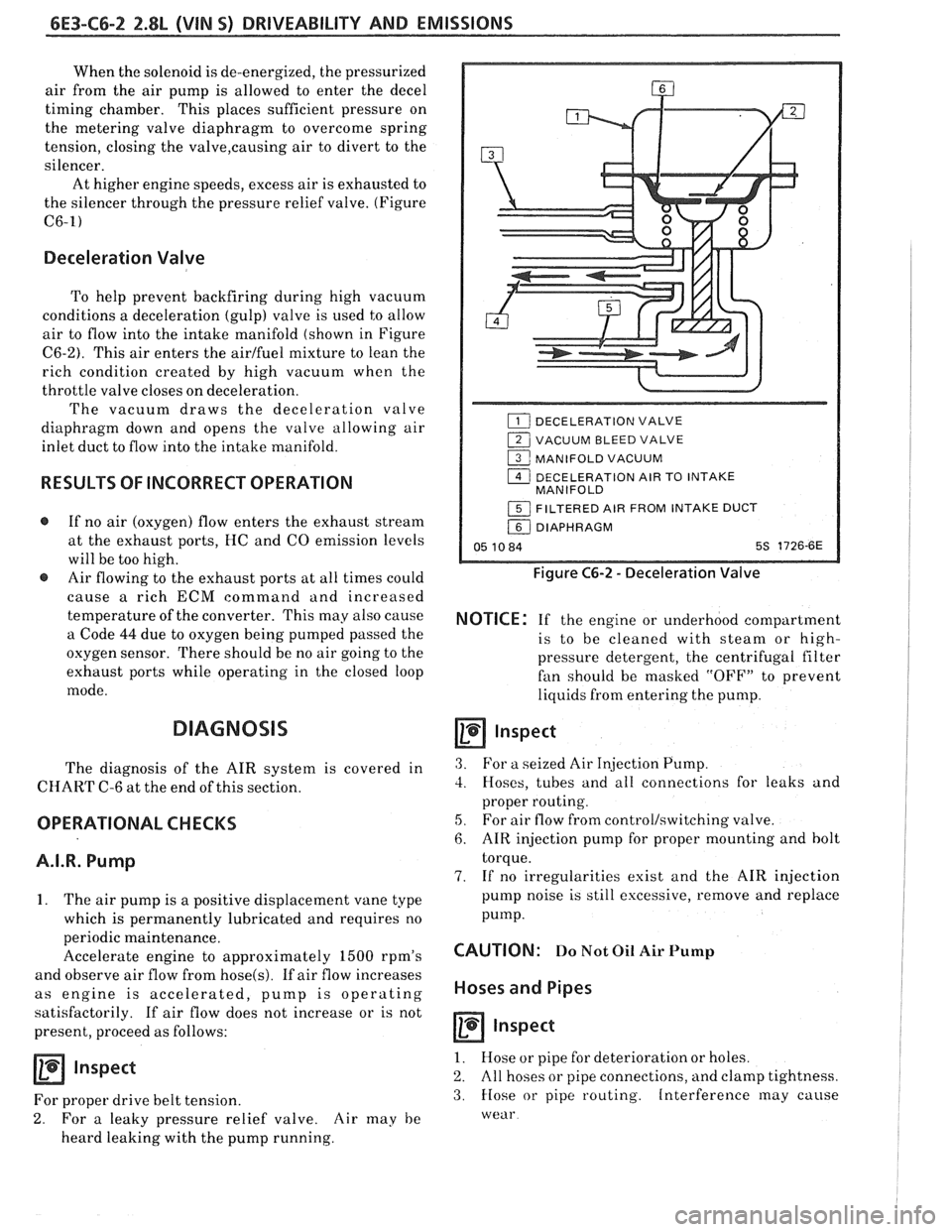
air to flow into the intake manifold (shown in Figure
C6-2). This air enters the airlfuel mixture to lean the
rich condition created by high vacuum when the
throttle valve closes on deceleration.
The vacuum draws the deceleration valve
diaphragm down and opens the valve allowing air
inlet duct to flow into the intake manifold.
RESULTS OF INCORRECT OPERATION
@ If no air (oxygen) flow enters the exhaust stream
at the exhaust ports, HC and
CO emission levels
will be too high.
@ Air flowing to the exhaust ports at all times could
cause
a rich ECM command and increased
temperature of the converter. This may also cause
a Code
44 due to oxygen being pumped passed the
oxygen sensor. There should be no air going to the
exhaust ports while operating in the closed loop
mode.
DIAGNOSIS
The diagnosis of the AIR system is covered in
CHART C-6 at the end of this section.
OPERATIONAL CHECKS
A.I.R. Pump
1. The air pump is a positive displacement vane type
which is permanently lubricated and requires no
periodic maintenance.
Accelerate engine to approximately
1500 rpm's
and observe air flow from
hose(s). If air flow increases
as engine is accelerated, pump is operating
satisfactorily. If air flow does not increase or is not
present, proceed as follows:
Inspect
For proper drive belt tension.
2. For a leaky pressure relief valve. Air may he
heard leaking with the pump running.
DECELERATION VALVE
1 VACUUM BLEED VALVE
1 MANIFOLD VACUUM
1 DECELERATION AIR TO INTAKE
MANIFOLD
1 FILTERED AIR FROM INTAKE DUCT
/ DIAPHRAGM
05 10 84 5s 1726-6E
Figure C6-2 - Deceleration Valve
NOTICE: If the engine or underhood compartment
is to he cleaned with
steam or high-
pressure detergent, the centrifugal filter
fan should be masked "OFF7' to prevent
liquids from entering the pump.
Inspect
3. For a seized Air Injection Pump.
3. Hoses, tubes and all connections for leaks and
proper routing.
5, For air flow from controllswitching valve.
6. AIR injection pump for proper mounting and bolt
torque.
7. If no irregularities exist and the AIR injection
pump noise is still excessive, remove and replace
pump.
CAUTION: Do Not Oil Air Pump
Hoses and Pipes
Inspect
1. Hose or pipe for deterioration or holes.
2. All hoses or pipe connections, and clamp tightness.
3. Hose or pipe routing. Interference may cause
wear
Page 787 of 1825
6E3-C8-2 2.8L (VIN S) DRIVEABILITY AND EMISSIONS
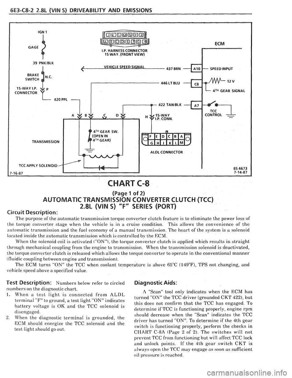
VEHICLE SPEED SIGNAL
SPEED INPUT
CONNECTOR
aTH GEAR SIGNAL
422 TAN/BLK
4TH GEAR SW.
TRANSMISSION
ALDL CONNECTOR
TCC APPLY SOLENOID
CHART C-8
(Page 1 of 2)
AUWBMATIC TRANSMISSION CONVERTER CLUTCH (TCC)
2.8L (VIN S) "F" SERIES (PORT)
Circuit Description:
The purpose of the automatic transmission torque converter clutch feature is to eliminate the power loss of
the torque converter stage when the vehicle is in a cruise condition. This allows the convenience of the
automatic transmission and the fuel economy of a manual transmission. The heart of the system is
a solenoid
located inside the automatic transmission which is controlled by the
ECM.
When the solenoid coil is activated ("ON"), the torque converter clutch is applied which results in straight
through mechanical coupling from the engine to transmission. When the transmission solenoid is deactivated,
the torque converter clutch is released which allows the torque converter to operate in the conventional manner
(fluidic coupling between engine and transmission).
The ECM turns
"ON" the 'KC when coolant temperature is above 65°C (14g°F), TPS not changing, and
vehicle speed above a specified value.
Test Description: Numbers below refer to circled Diagnostic Aids:
numbers on the diagnostic chart. A "Scan" tool only indicates when the ECM has 1. When a test light is connected from ALDL turned the TCC driver (grounded CKT 422), but terminal "F" to ground, a test light "ON" indicates
this does not confirm that the TCC has engaged. To battery voltage is OK and the TCC solenoid is
determine if TCC is functioning properly, engine rpm
disengaged.
should decrease when the "ScanJ' indicates the TCC
2. When the diagnostic terminal is grounded, the
driver has turned "ON". To determine if the 4th gear ECM energize the TCC "Ienoid and the switch is functioning properly, perform the checks in
test light should go out.
CIIART C-8A (Page 2 of 2). The switches will not
prevent TCC fi-om functioning but will affect TCC lock
and unlock points. If the 4th gear switch CKT is
always open the
TCC may engage as soon as sufficient
oil
pl.essure is reached.