1988 PONTIAC FIERO oil temperature
[x] Cancel search: oil temperaturePage 420 of 1825
ENGINE COOLING 6B-9
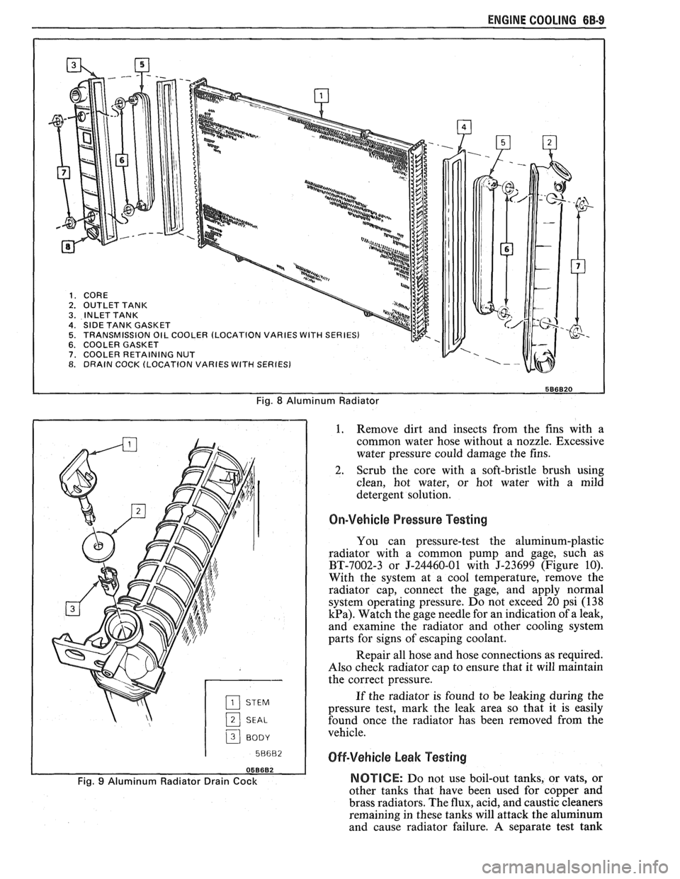
Fig. 8 Aluminum Radiator
2 SEAL
3 BODY I
1. Remove
dirt and insects from the fins with a
common water hose without a nozzle. Excessive
water pressure could damage the fins.
2. Scrub the core with a soft-bristle brush using
clean, hot water, or hot water with a mild
detergent solution.
On-Vehicle Pressure Testing
You can pressure-test the aluminum-plastic
radiator with a common pump and gage, such as
BT-7002-3 or J-24460-01 with J-23699 (Figure 10).
With the system at a cool temperature, remove the
radiator cap, connect the gage, and apply normal
system operating pressure. Do not exceed 20 psi (138
kPa). Watch the gage needle for an indication of a leak,
and examine the radiator and other cooling system
parts for signs of escaping coolant.
Repair all hose and hose connections as required.
Also check radiator cap to ensure that it will maintain
the correct pressure.
If the radiator is found to be leaking during the
pressure test, mark the leak area so that it is easily
found once the radiator has been removed from the
vehicle.
Off-Vehicle beak Testing
Fig. 9 Aluminum Radiator Drain Cock NOTICE: Do not use boil-out tanks, or vats, or
other tanks that have been used for
couuer and
brass radiators. The flux, acid, and
caustiE cleaners
remaining in these tanks will attack the aluminum
and cause radiator failure. A separate test tank
Page 464 of 1825
CHARGING SYSTEM 6D3-1
SECTION 6D3
CHARG NG SYSTEM
CONTENTS
General Description ................................. 6D3- 1 Charging System ........................................ 6D3- 1
.......................................... Charging System - CS ............................... 6D3- 1 On-Car Service 6D3-2
................................................... Diagnosis .. 6D3- 1 Generator 6D3-3 ...................... ......................... ............................................. 6D3- 1 Specifications 6D3-3 Service Procedures .................................. Unit Repair .. 6D3-4-6 ............................... ............
GENERAL DESCRIPTION
The engine electrical system includes the battery,
ignition (primary and secondary), starter (and related
wiring) and the generator (and related wiring).
Diagnostic charts (see Section 6D) will aid in
trouble-shooting system faults. When a fault is traced
to a particular component, refer to that components'
section of the service manual.
CHARGING SYSTEM-CS
The CS Charging System has several sizes
available, including the CS-130 and CS-144. The
number (130 or 144) denotes the
OD in mm of the
stator laminations.
CS generators use a new type regulator and a
diode trio is not used. A delta stator, rectifier bridge,
and rotor with slip rings and brushes are electrically
similar to earlier generators. A conventional pulley and
fan is used and, on the CS-130, an internal fan cools the
slip ring end frame, rectifier bridge and regulator.
Unlike three-wire generators, the CS-130 and
CS-144 may be used with only two connections
-
battery positive and an "L" terminal to the charge
indicator bulb. Use of "P",
"F", and "S" terminals is
optional. The "P" terminal is connected to the stator,
and may be connected externally to
a tachometer or other
device. The
"F" terminal is connected internally
to field positive, and may be used as a fault indicator.
The "S" terminal may be connected externally to a
voltage, such as battery voltage, to sense voltage to be
controlled.
As on other charging systems, the charge
indicator lights when the switch is closed, and goes out
when the engine is running. If the charge indicator is
on with the engine running, a charging system defect
is indicated. For all kinds of defects, the indicator will
glow at full brilliance, not "half lit". Also, the charge
indicator will be on with the engine running if system
voltage is too high or too low. The regulator voltage
setting varies with temperature, and limits system
voltage by controlling rotor field current.
This regulator switches rotor field current on and
off at a fixed frequency of about 400 cycles per second.
By varying the on-off time, correct average field
current for proper system voltage control is obtained.
At high speeds, the on-time may be 10% and the
off-time 90%. At low speeds, with high electrical loads,
on-off time may be 90% and
lo%, respectively.
No periodic maintenance on the generator is
required.
DIAGNOSIS
SERVICE PROCEDURES
CHARGING SYSTEM
The generator does not require periodic
lubrication. The rotor shaft is mounted on ball bearings
at the drive end and roller bearings at the slip ring end.
Each contains a permanent grease supply. At periodic
intervals, check mounting bolts for tightness and adjust
belt tension (see Section
6B), if applicable.
e When adjusting belt tension, apply pressure at
center of generator, never against either end
frame.
GENERATOR BENCH CHECK-CS
To check generator in a test stand, remove as
specified in On-Car Service and proceed as follows: 1.
Make connections as shown in Figure
lH, except
leave the carbon pile disconnected. The ground
polarity of generator and battery must be the
same. The battery must be fully charged. Use a
30-500
OHM resistor between battery and "L"
terminal.
2. Slowly increase generator speed and observe
voltage.
3. If the voltage is uncontrolled and increases above
16.0 volts, the rotor field is shorted, the regulator
is defective, or both.
A shorted rotor field coil can
cause the regulator to become defective. NOTE:
The battery must be fully charged when making
this test.
Page 470 of 1825
IGNITION SYSTEM 6D4-1
ON SYSTEM
CONTENTS
General Description ............................... 6D4-1 Service Procedures ............................. 6D4-3
Ignition System .......................................... 6D4-1
Ignition System .......................................... 6D4-3
Distributor Ignition ................................ 6D4-1
Distributor Ignition ................................ 6D4 -3
Diannosis .................................................... 6D4-3 On-Car Service ......................................... 6D4-5 -
Ignition System .......................................... (334-3 Ignition System ........................... .. .............. 6D4-5
Distributor ................................................. 6D4 -7 HE1 Distributor .................................... 6D4-3
GENERAL DESCRIPION
The engine electrical system includes the battery,
ignition (primary and secondary), starter (and related
wiring) and the generator (and related wiring).
Diagnostic charts (see Section 6D) will aid in
trouble-shooting system faults. When a fault is traced
to a particular component, refer to that components'
section of the service manual.
IGNITION SYSTEM
Distributor Ignition
The ignition circuit consists of the battery,
distributor, ignition switch, spark plugs and primary
and secondary wiring. Refer to the Battery portion of
this section for battery information.
PIE1 Distributor
The Nigh Energy Ignition (HEI) distributor with
Electronic Spark Timing (EST), used on most engines,
combines all ignition components in one unit. The
ignition coil is in the distributor cap and connects
through a resistance brush to the rotor.
The distributor has an internal magnetic pick-up
assembly which contains a permanent magnet, a pole
piece with internal teeth and a pick-up coil. When the
teeth of the timer core, rotating inside the pole piece,
line up with the teeth of the pole piece, an induced
voltage in the pick-up coil signals the electronic module
to trigger the coil primary circuit. The primary current
decreases and a high voltage is induced in the ignition
coil secondary winding. This voltage is directed
through the rotor and secondary leads to fire the spark
plugs. The capacitor in the distributor is for radio noise
suppression,
All spark timing changes in the
HE1 (EST)
distributor are done electronically by an Electronic
Control Module (ECM), which monitors information
from various engine sensors, computes the desired
spark timing and signals the distributor to change the
timing accordingly.
A back-up spark advance system
is incorporated to signal the ignition module in case of
(ECM) failure. No vacuum or mechanical advance is
used. Further (EST) information is found in sections 6E
Emissions Control, and
8A Electrical
Troubleshooting.
Ignition Timing
Timing specifications for each engine are listed in
Section
6E. When using a timing light, connect an
adapter between the No. 1 spark plug and the No. 1
spark plug wire, or use an inductive type pick-up.
Do
not pierce the plug lead.
Once the insulation of the
spark plug cable has been broken, voltage will jump to
the nearest ground, and the spark plug will not fire
properly.
Always follow the tune-up label
procedures when adjusting timing.
Some engines will incorporate a magnetic timing
probe hole for use with special electronic timing
equipment. Fig.
1A shows a typical magnetic probe
hole. Consult manufacturer's instructions for use of
this equipment.
Secondary Wiring
The spark plug wiring used with ignition systems
is a carbon impregnated cord conductor, encased in an
8MM (5/16") diameter silicone rubber jacket. The
silicone jacket withstands very high temperatures and
also provides an excellent insulator for the higher
voltage of the
HE1 system. Silicone spark plug boots
form a tight seal on the plug.
The boot should be
twisted 1/2 turn before removing. Care should
also be exercised when connecting a timing light or
other pick-up equipment. Do not force anything
between the boot and wiring, or through the silicone
jacket. Connections should be made in parallel using
an adapter. DO NOT pull on the wire to remove. Pull
on the boot, or use a tool designed for this purpose.
Spark Plugs
Resistor type, tapered seat spark plugs are used
on all engines (except aluminum heads). No gasket is
used on these tapered seat plugs. See Figs.
1B and 1C
for an explanation of coding on spark plugs.
Normal service is assumed to be a mixture of
idling, slow speed, and high speed driving. Occasional
or intermittent high-speed driving is needed for good
Page 472 of 1825
IGNITION SYSTEM 6B4-3
flash-over, which causes engine misfiring. Do not
mistake corona discharge for flash-over, or a shorted
insulator. Corona is a steady blue light appearing
around the insulator, just above the shell crimp. It is
the visible evidence of a high-tension field and has no
effect on ignition performance. Usually it can be
detected only in darkness. This discharge may repel
dust particles, leaving a clear ring on the insulator just
above the shell. This ring is sometimes mistakenly
regarded as evidence that combustion gases have blown
out between shell and insulator.
lgnition Switch
The mechanical switch is located in the steering
column on the right hand side just below the steering
wheel. The electrical switching portion of the assembly
is separate from the key and lock cylinder. However,
both are synchronized and work in conjunction with
each other through the action of the actuator rod
assembly.
For a complete explanation of the key and lock
cylinder, and the actuator rod assembly, see
STEERING, Section
38. See Section 8 for electrical
switching.
DIAGNOSIS
IGNITION SYSTEM
Spark Plugs
Worn or dirty plugs may give satisfactory
operation at idling speed, but at higher RPM they
frequently fail. Faulty plugs are indicated in a number
of ways: poor fuel economy, power loss, loss of speed,
hard starting and generally poor engine performance.
Spark plugs may also fail due to carbon fouling,
excessive gap, or a broken insulator. Fouled plugs may
be indicated by black carbon
deposits. The black deposits are usually the result of
slow-speed driving and short runs, where sufficient
engine operating temperature is seldom reached. Worn
pistons, rings, faulty ignition, over-rich carburetion
and spark plugs which are too cold will also result in
carbon deposits.
Excessive gap wear, on plugs of low mileage,
usually indicates the engine is operating at high speeds,
or loads that are consistently greater than normal, or
that a plug which is too hot is being used. Electrode
wear may also be the result of plug overheating,
causcd
by combustion gases leaking past the threads due to
insufficient torquing of the spark plug. Excessively lean
carburetion will also result in accelerated electrode
wear.
Broken insulators are usually the result of
improper installation, or carelessness when regapping
the plug. Broken upper insulators usually result from
a poor fitting wrench, or an outside blow. The cracked
insulator may not show up right away, but will as soon
as oil or moisture penetrates the crack. The crack is
usually just below the crimped part of shell and may
not be visible.
Broken lower insulators usually result from
carelessness when regapping and generally are visible.
This type of break may result from the plug operating
too "hot", which may happen in periods of high-speed
operation or under heavy loads. When regapping a
spark plug, always make the gap adjustment by
bending the ground (side) electrode. Spark plugs with
broken insulators should always be replaced.
HE1 Distributor
See Unit Repair for distributor disassembly, test
and reassembly of individual distributor components,
when the distributor is removed from the vehicle. See
On-Car Service for distributor removal and installation
and for component removal with distributor in car. See
Section 6E for
HE1 and EST diagnosis.
SERVICE PROCEDURES
IGNITION SYSTEM
Distributor Ignition
NOTICE: This procedure is generally true for
most carlines. Where procedure is different, or
where additional information is required, see
"ON-CAR SERVICE" for specific
carline.
HE1 DISTRIBUTOR
Service Precautions
1. When making compression checks, disconnect
the ignition switch feed wire at the distributor.
When disconnecting this connector,
do not use
a screwdriver or tool to release the locking tab, as
it may break.
2. No periodic lubrication is required. Engine oil
lubricates the lower bushing and an oil-filled
reservoir provides lubrication for the upper
bushing. 3.
The tachometer (TACH) terminal is next to the
ignition switch (BAT) connector on the
distributor cap.
NOTICE: The tachometer terminal must
NEVER be allowed to touch ground, as damage
to the module and/or ignition coil can result.
Some tachometers currently in use may NOT be
compatible with the High Energy Ignition System.
Consult the manufacturer of the tachometer if
questions arise.
4. Dwell adjustment is controlled by the module,
and cannot be adjusted.
5. The material used to construct the spark plug
cables is very soft. This cable will withstand more
heat and carry a higher voltage, but scuffing and
cutting become easier. The spark plug cables
must be routed correctly to prevent
chafing or
cutting. See Spark Plug Section. When removing
Page 482 of 1825
ENGINE ELECTRICAL 6B.l
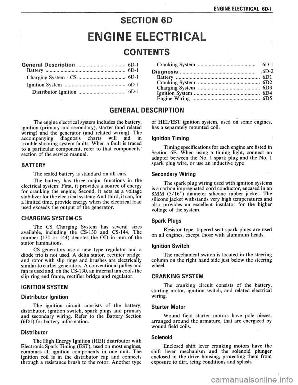
SECTION 6D
NE ELECTR
General Description ................................... 6D- 1 Cranking System ..................................... 6D- 1
Battery .................... ... .............................. 6D- 1 ....................................................... Diagnosis ,6D-2
.................................. Charging System - CS 6D- 1 Battery ................... .. ..................................... 6D1
......................................... Ignition System ............................................ 6D- 1 Cranking System 6D2
Charging System .......................... .. ............... 6D3 .................................. Distributor Ignition 6D- 1 Ignition Svstem .......................................... 6D4 - Engine Wiring ................................................ 6D5
GENERAL DESCRIPTION
The engine electrical system includes the battery,
ignition (primary and secondary), starter (and related
wiring) and the generator (and related wiring). The
accompanying diagnosis charts will aid in
trouble-shooting system faults. When a fault is traced
to a particular component, refer to that components'
section of the service manual.
BATTERY
The sealed battery is standard on all cars.
The battery has three major functions in the
electrical system: First, it provides a source of energy
for
cranking the engine; Second, it acts as a voltage
stabilizer for the electrical system; And third, it can, for
a limited time, provide energy when the electrical load
used exceeds the output of the generator.
CHARGING SYSTEM-CS
The CS Charging System has several sizes
available, including the CS-130 and CS-144. The
number (130 or 144) denotes the
OD in mm of the
stator laminations.
CS generators use a new type regulator and a
diode trio is not used. A delta stator, rectifier bridge,
and rotor with slip rings and brushes are electrically
similar to earlier generators. A conventional pulley and
fan is used and, on the CS-130, an internal fan cools the
slip ring end frame, rectifier bridge and regulator.
IGNITION SYSTEM
Distributor Ignition
The ignition circuit consists of the battery,
distributor, ignition switch, spark plugs and primary
and secondary wiring. Refer to the Battery Section
(6D 1) for battery information.
Distri but~r
The High Energy Ignition (HEI) distributor with
Electronic Spark Timing (EST), used on most engines,
combines all ignition components in one unit. The
ignition coil is in the distributor cap and connects
through a resistance brush to the rotor. Another type of
HEVEST ignition system,
used on some engines,
has a separately mounted coil.
Ignition Timing
Timing specifications for each engine are listed in
Section 6E. When using a timing light, connect an
adapter between the No. 1 spark plug and the No. 1
spark plug wire, or use an inductive type
Secondary Wiring
The spark plug wiring used with ignition systems
is a carbon impregnated cord conductor, encased in an
8MM (5/16") diameter silicone rubber jacket. The
silicone jacket withstands very high temperatures and
also provides an excellent insulator for the higher
voltage of the system.
Spark Plugs
Resistor type, tapered seat spark plugs are used
on all engines, except those with aluminum heads.
lgnition Switch
The mechanical switch is located in the steering
column on the right hand side just below the steering
wheel.
CRANKING SYSTEM
The cranking circuit consists of the battery,
starting motor, ignition switch, and related electrical
wiring.
Starter Motor
Wound field starter motors have pole pieces,
arranged around the armature, that are energized by
wound field coils.
Solenoid
Enclosed shift lever cranking motors have the
shift lever mechanism and the solenoid plunger
enclosed in the drive housing, protecting them from
exposure to dirt, icing conditions and splash.
Page 493 of 1825
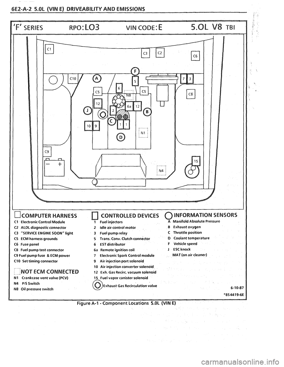
6E2-A-2 5.OL (VIN E) DRIVEABILIW AND EMISSIONS
IFf SERIES VIN CODE: E
OCOMPUTER HARNESS
C1 Electronic Control Module
C2 ALDL diagnostic connector
C3 "SERVICE ENGINE SOON" light
C5 ECM harness grounds
C6 Fuse panel
C8 Fuel pump test connector
C9 Fuel pump fuse & ECM power
C10 Set timing connector
....,
: . ... 'NOT ECM CONNECTED
N1 Crankcase vent valve (PCV)
N4 PIS Switch
N8 Oil pressure switch
[7 CONTROLLED DEVICES 0 INFORMATION SENSORS
1 Fuel injectors A Manifold Absolute Pressure
2 Idle air control motor B Exhaust oxygen
3 Fuel pump relay
C Throttle position
5 Trans. Conv. Clutch connector
D Coolant temperature
6 EST distributor
F Vehicle speed
6a Remote ignition coil
J ESCknock
7 Electronic Spark Control module MAT (on air cleaner)
9 Air injection port solenoid
10 Air injection converter solenoid
12 Exh. Gas Recirc. vacuum solenoid
15 Fuel vapor canister solenoid
Exhaust Gas Recirculation valve
6-1
0-87
Figure A-I - Component Locations 5.OL (VIN E)
Page 553 of 1825
6E2-8-6 5.OL (VIN E) DRIVEABILITY AND EMISSIONS
- MAP Sensor - Ignition "ON", engine stopped.
Compare MAP voltage with known good vehicle.
-
Voltage should be the same + 400 mV (.4 volts).
OR
Start and idle engine. Disconnect
sensor
electrical connector. If idle improves, substitute
a known good sensor and recheck.
- A/C refrigerant pressure too high. Check for
overcharge or faulty pressure switch.
- PCV valve for proper operation by placing finger
over inlet hole in valve end several times. Valve
should snap back. If not, replace valve.
Run a cylinder compression check See Section
" 6".
Inspect oxygen sensor for silicon contamination
from fuel, or use of improper RTV sealant. The
sensor will have a white, powdery coating, and
will result in a high but false signal voltage (rich
exhaust indication). The ECM will then reduce
the amount of fuel delivered to the engine,
causing a severe driveability problem.
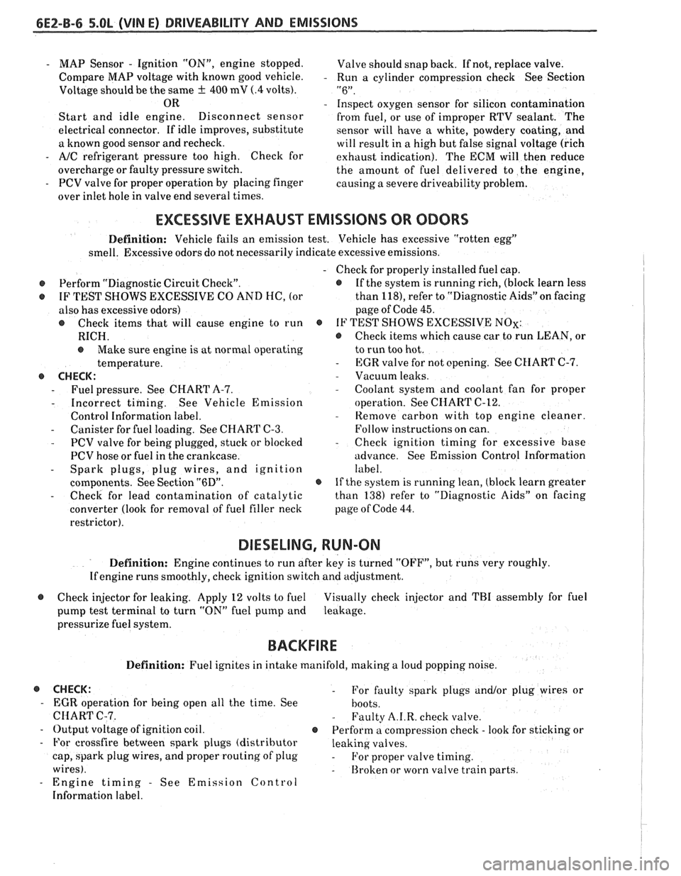
EXCESSIVE EXHAUST EMISSIONS OR ODORS
Definition: Vehicle fails an emission test. Vehicle has excessive "rotten egg"
smell. Excessive odors do not necessarily indicate excessive emissions.
@ Perform "Diagnostic Circuit Check".
@ IF TEST SHOWS EXCESSIVE CO AND HC, (or
also has excessive odors)
@ Check items that will cause engine to run
RICH.
e Make sure engine is at normal operating
temperature.
o CHECK:
- Fuel pressure. See CHART A-7.
- Incorrect timing. See Vehicle Emission
Control Information label.
- Canister for fuel loading. See CHART C-3.
- PCV valve for being plugged, stuck or blocked
PCV hose or fuel in the crankcase.
- Spark plugs, plug wires, and ignition
components. See Section
"6D".
- Check for lead contamination of catalytic
converter (look for removal of fuel filler neck
restrictor).
- Check for properly installed fuel cap.
@ If the system is running rich, (block learn less
than
1181, refer to "Diagnostic Aids" on facing
page of Code
45.
o IF TEST SHOWS EXCESSIVE NOx:
@ Check items which cause car to run LEAN, or
to run too hot.
- EGR valve for not opening. See CHART C-7.
- Vacuum leaks. - Coolant system and coolant fan for proper
operation. See
CHART C-12.
- Remove carbon with top engine cleaner.
Follow instructions on can.
- Check ignition timing for excessive base
advance. See Emission Control Information
label.
@ If the system is running lean, (block learn greater
than
138) refer to "Diagnostic Aids" on facing
page of Code
44.
DIESELING, RUN-ON
Definition: Engine continues to run after key is turned "OFF", but runs very roughly.
Ifengine runs smoothly, check ignition switch and adjustment.
@ Check injector for leaking. Apply 12 volts to fuel Visually check injector and TBI assembly for fuel
pump test terminal to turn "ON" fuel pump and leakage.
pressurize fuel system.
BACKFIRE
Definition: Fuel ignites in intake manifold, making a loud popping noise.
@ CHECK: - For faulty spark plugs and/or plug wires or
- EGR operation for being open all the time. See
hoots.
CHART C-7. - Faulty A.I.R. check valve.
- Output voltage of ignition coil. @ Perform a compression check - look for sticking or
- For crossfire between spark plugs (distributor leaking valves.
cap, spark plug wires, and proper routing' of plug
- For proper valve timing.
wires).
- Broken or worn valve train parts.
- Engine timing - See Emission Control
Information label.
Page 560 of 1825
DRIVEABILITY AND EMISSIONS 5.OL (VIN E) 6EZ-C1-5
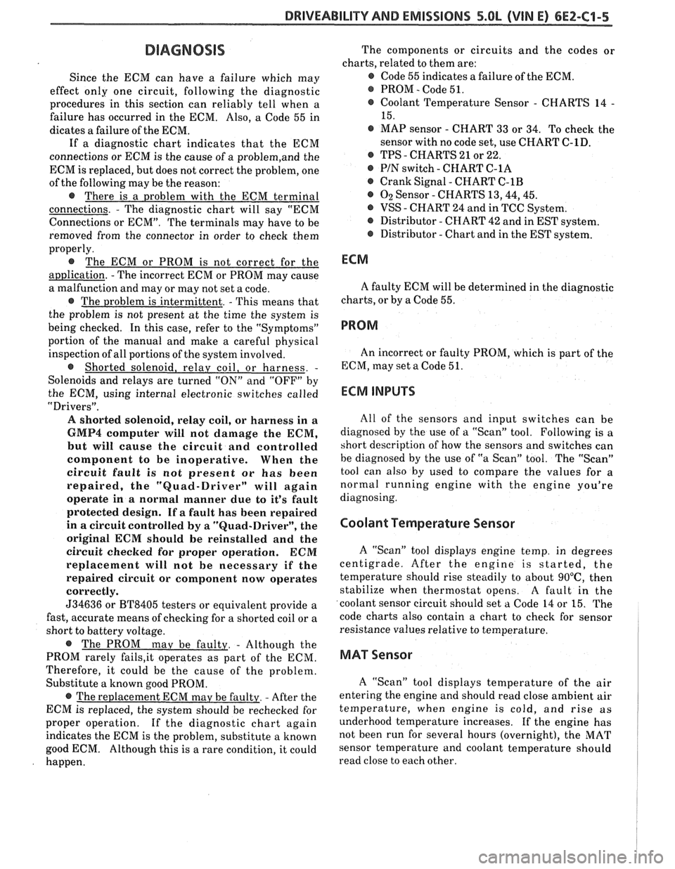
DIAGNOSIS
Since the ECM can have a failure which may
effect only one circuit, following the diagnostic
procedures in this section can reliably tell when a
failure has occurred in the ECM. Also,
a Code
55 in
dicates a failure of the ECM.
If a diagnostic chart indicates that the ECM
connections or ECM is the cause of a
problem,and the
ECM is replaced, but does not correct the problem, one
of the following may be the reason:
e
connections. - The diagnostic chart will say "ECM
Connections or ECM". The terminals mav have to be
removed from the connector in order to check them
properly.
@ The ECM or PROM is not correct for the
. - The incorrect ECM or PROM may cause
a malfunction and may or may not set a code.
. - This means that
time the system is
being checked. In this case, refer to the "Symptoms"
portion of the manual and make a careful physical
Solenoids and relays are turned "ON" and "OFF" by
the ECM, using internal electronic switches called
"Drivers".
A shorted solenoid, relay coil, or harness in a
GMP4 computer will not damage the ECM,
but will cause the circuit and controlled
component to be inoperative. When the
circuit fault is not present or has been
repaired, the "Quad-Driver" will again
operate in a normal manner due to it's fault
protected design. If a fault has been repaired
in a circuit controlled
by a "Quad-Driver", the
original
ECM should be reinstalled and the
circuit checked for proper operation.
ECM
replacement will not be necessary if the
repaired circuit or component now operates
correctly.
534636 or BT8405 testers or equivalent provide a
fast, accurate means of checking for a shorted coil or a
short to battery voltage.
e , - Although the
PROM rarely
fails,it operates as part of the ECM.
Therefore, it could be the cause of the problem.
Substitute a known good PROM.
o . - After the
ECM is replaced, the system should be rechecked for
proper operation. If the diagnostic chart again
indicates the ECM is the problem, substitute a known
good ECM. Although this is a rare condition, it could
happen. The
components or circuits and the codes or
charts, related to them are:
@ Code 55 indicates a failure of the ECM.
@ PROM - Code 51.
@ Coolant Temperature Sensor - CHARTS 14 -
15.
@ MAP sensor - CHART 33 or 34. To check the
sensor with no code set, use CHART
C-1D.
e TPS - CHARTS 21 or 22.
e PIN switch - CHART C-1A
@ Crank Signal - CHART C-1B
@ O2 Sensor - CHARTS 13,44,45.
@ VSS - CHART 24 and in TCC System.
e Distributor - CHART 42 and in EST system.
@ Distributor - Chart and in the EST system.
ECM
A faulty ECM will be determined in the diagnostic
charts, or by a Code 55.
PROM
An incorrect or faulty PROM, which is part of the
ECM, may set a Code 51.
ECM INPUTS
All of the sensors and input switches can be
diagnosed by the use of a "Scan" tool. Following is
a
short description of how the sensors and switches can
be diagnosed by the use of "a Scan" tool. The
"Scan"
tool can also by used to compare the values for a
normal running engine with the engine you're
diagnosing.
Coolant Temperature Sensor
A "Scan" tool displays engine temp. in degrees
centigrade. After the engine is started, the
temperature should rise steadily to about
90°C, then
stabilize when thermostat opens.
A fault in the
coolant sensor circuit should set a Code 14 or 15. The
code charts also contain a chart to check for sensor
resistance values relative to temperature.
MAT Sensor
A "Scan" tool displays temperature of the air
entering the engine and should read close ambient air
temperature, when engine is cold, and rise
as
underhood temperature increases. If the engine has
not been run for several hours (overnight), the MAT
sensor temperature and coolant temperature should
read close to each other.