1988 PONTIAC FIERO oil temperature
[x] Cancel search: oil temperaturePage 973 of 1825
6E-12 DRIVEABILITY AND EMISSIONS - FUEL INJECUION
and MPH) for abbreviations used in this Section, but
all types are acceptable.
NA/F - AI WFUEL (NF RATIO)
A.I.R.
- AIR INJECTOR REACTION SYSTEM - Air
flow from pump is directed into engine exhaust
manifold
and/or converter to reduce exhaust
emissions.
ALDL - ASSEMBLY LINE DIAGNOSTIC LINK - Used
at assembly to evaluate Computer Command Control,
and for service to flash the "Service Engine Soon"
light
if there are trouble codes. It also is used by
"Scan" tools to obtain ECM serial data.
BARO - BAROMETRIC ABSOLUTE PRESSURE
SENSOR
- Reads atmospheric pressure.
B + - Battery Positive Terminal (12 Volts) or
system voltage with the engine running
(approximately 13.8
v.)
CALPAK - A device used with fuel injection to
allow fuel delivery in the event of a PROM or ECM
malfunction.
CALIBRATOR - (PROM) - An electronic component
that can be
specifically programmed to meet engine
operating requirements for a
specific vehicle model.
It plugs into the Engine Control Module
(ECM).
CCC - COMPUTER COMMAND CONTROL - has an
electronic control module to control airlfuel and
emission systems.
CLCC - CLOSED LOOP CARBURETOR CONTROL -
Used to describe oxygen sensor to ECM to MIC
solenoid circuit operation.
C3I - Computer Controlled Coil Ignition. Produces
the ignition spark without the aid of an ignition
distributor.
CCP - CONTROLLED CANISTER PURGE - ECM
controlled solenoid valve that permits manifold
vacuum to purge the evaporative emissions from the
charcoal canister.
CID - CUBIC INCH DISPLACEMENT - Used to
describe engine size.
UL OR ULOOP - "CLOSED LOOP" - Describes ECM
fuel control when using oxygen sensor information.
COOLANT TEMPERATURE SENSOR - Device that
senses the engine coolant temperature, and passes
that information to the engine control module.
CONV. - CATALYTIC CONVERTER, THREE-WAY -
EXHAUST CONVERTER. Containing platinum and
palladium to speed up conversion of
HC and CO, and
rhodium to accelerate conversion of NO,.
CO - CARBON MONOXIDE - One of the pollutants
found in engine exhaust.
6V - CRANKCASE VENTlhaflON - Prevents fumes
in crankcase from passing into the atmosphere, by
drawing them into the intake manifold and burning
them in the the combustion process.
DIAGNOSTIC CODE - Pair of numbers obtained
from flashing "Service Engine Soon" light or
displaying on a "Scan" tool. This code can be used to
determine the system malfunction.
DIAGNOSTIC TERM. - Lead of ALDL Connector
which is grounded to get a Trouble Code.
It is
grounded with the engine running to enter the "Field
Service Mode".
DIS - Direct Ignition System. Produces the
ignition spark without the aid of an ignition
distributor.
DVM (10 Meg.) - Digital Voltmeter with 10 Million
ohms resistance
- used for measurement in electronic
systems.
DWELL - The amount of time (recorded on a dwell
meter in degrees of crankshaft rotation) that current
passes through a closed switch; for example, ignition
contact points or internal switch in an electronic
control module.
EAC - ELECTRIC AIR CONTROL - Used on A.I.R.
system to direct air flow to air switching valve or to
atmosphere.
EAS - ELECTRIC AIR SWITCHING - used to direct air
flow to catalytic converter or exhaust ports of the
engine.
ECM - ENGINE CONTROL MODULE (ELECTRONIC) -
A metal case (located in passenger compartment)
containing electronic circuitry which electrically
controls and monitors airlfuel and emission systems
on computer command control, and turns
"ON" the
"Service Engine Soon" light when a malfunction
occurs in the system.
EFI - ELECTRONIC FUEL INJECTION - Computer
Command Control using throttle body fuel injection.
EGR - EXHAUST GAP REClRCUbATlON - Method of
reducing NO, emission levels by causing exhaust gas
to be added to airlfuel mixture in combustion
chamber, thus cooling combustion.
EECS - EVAPORATIVE EMISSIONS CONTROL
SYSTEM
- Used to prevent gasoline vapors in the fuel
tank from entering the atmosphere.
EFE - EARLY FUEL EVAPORATION - Method of
warming the intake manifold during cold engine
operation. Provides efficient airlfuel mixing.
ENERGIZEIDE-ENERGIZE - When current is passed
through a coil (energized) such as the canister purge
solenoid, the plunger is pulled into the solenoid.
Page 974 of 1825
DRIVEABILIW AND EMISSIONS - FUEL INJECTION 6E-13
When the voltage to the solenoid is turned off, (de-
energized), a spring raises the plunger.
ESC - ELECTRONIC SPARK CONTROL - Used to
sense detonation and retard spark advance when
detonation occurs.
EST - ELECTRONIC SPARK TIMING - ECM
controlled timing of ignition spark.
EVRV - ELECTRONIC VACUUM REGULAWR
VALVE - Controls EGR vacuum.
FED - FEDEWL - VehicleIEngine available in all
states except California.
GROUND - The negative (-) side of the battery.
Also could be a wire (conductor) shorted to ground.
HC - HYDROCARBONS - One of the pollutants
found in engine exhaust.
HIGH IMPEDANCE VOLTMETER - Mas high
opposition to the flow of electrical current.
Good for
reading circuits with low current flow, such as found
in electronic systems because it allows tests to be
made without affecting the circuit.
HE1 - HIGH ENERGY IGNITION - A distributor that
uses an electronic module and pick-up coil in place of
contact points.
Hg - MERCURY - A calibration material used as a
standard for vacuum measurement.
IAC - IDLE AIR CONTROL - A valve installed in the
throttle body of fuel injected systems and controlled by
the ECM to regulate idle speed.
IDEAL MIXWRE - The airlfuel ratio which provides
the best performance, while maintaining maximum
conversion of exhaust emissions. Typically it is
14.7:1.
ID1 - INTEGRATED DIRECT IGNITION - Produces the
ignition spark without the aid of an ignition
distributor or spark plug wires.
IDLE AIR BLEED VALVE - Controls the amount of
air let into the idle fuel mixture prior to the mixture
entering the carburetor idle system, when the
MIC
solenoid is energized.
ILC - IDLE LOAD COMPENSATOR - Device used to
control throttle angle during long deceleration, such
as coasting down a long grade; it extends at wide open
throttle position or to prevent engine stalls at idle.
INPUTS - Information from sources (such as
coolant temperature sensors, exhaust oxygen sensor,
etc.) to the ECM that indicate how the systems are
performing.
INTERMITTENT - Occurs now and then; not
continuously. In electrical circuits, refers to
occasional open, short, or ground.
I.P. - INSTRUMENT PANEL
ISC - IDLE SPEED CONTROL - Regulates throttle
valve position to control idle speed. Idle speed is
controlled by the ECM and is not adjustable.
KMIHR - KILOMEnR PER HOUR - A metric unit
measuring speed needed to travel distance of one
kilometer (1000 meters) in one hour.
L - LITER - A metric unit of capacity.
L4 - FOUR CYLINDER IN-LINE ENGINE
MAF - MASS AIR FLOW - Sensor which measures
the amount of air entering the engine.
MALFUNCTION - A problem that causes the
system to operate incorrectly. Typical malfunctions
are wiring harness opens or shorts, failed sensors or
circuit components.
MANIFOLD VACUUM SENSOR - Indicates vacuum
in the intake manifold by measuring the pressure in
intake manifold in relation to barometric pressure. It
is also called a differential pressure sensor because
it
measures the difference between the two pressures. It
puts out a voltage which is highest when the vacuum
is highest. The maximum voltage is between 4 and 5
volts.
MAP - MANIFOLD ABSOLUTE PRESSURE SENSOR -
Reads pressure changes in intake manifold with
reference to zero pressure. It puts out a voltage which
is highest when the pressure is highest. The
maximum voltage is between
4 and 5 volts.
MAT - Manifold Air Temperature Sensor.
Measures temperature of air in the intake manifold.
MIC - MIXTURE CONTROL
MEM-CAL
- MEMORY CALIBRATOR - Contains
specific calibrations to meet the requirements of a
specific engine.
MFI - MULTlPORT FUEL INJECnON - Individual
injectors for each cylinder are mounted in the intake
manifold. The injectors are fired in groups rather than
individually.
MIXTURE CONTROL (MIC) SOLENOID - Device,
installed in carburetor, to regulate the airlfuel ratio.
MODE - A particular state of operation.
MPH - MILES PER HOUR - A unit measuring speed
needed to travel distance of one mile (5280 feet) in one
hour.
N.C. - NORMALLY CLOSED - State of relay contacts
or solenoid plunger when no voltage is applied.
N-rn - NEWTON METER (Torque) - A metric unit
describing force.
Page 975 of 1825
6E-14 DRIVEABILITY AND EMISSIONS - FUEL INJECTION
N.O. - NORMALLY OPEN - State of relay contacts
or solenoid plunger when no voltage
is applied.
NOx - NITROGEN, OXIDES OF - One of the
pollutants found in engine exhaust.
O2 - OXYGEN (Sensor) - Monitors the oxygen
content of the exhaust system and generates a voltage
signal to the ECM.
OIL or OILOOP - OPEN LOOP - Describes ECM fuel
control without use of oxygen sensor information.
OUTPUT - Result of a function typically controlled
by the ECM.
OXYGEN SENSOR. EXHAUST - Device that detects
the amount of oxygen
(02) in the exhaust stream.
P.A.1.R - PULSE AIR INJECTION REACTOR system -
pulsed air directed into engine to reduce exhaust
emissions.
PCV - POSITIVE CRANKCASE VENTILATION -
Prevent fumes in crankcase from passing into
atmosphere.
PFI - PORT FUEL INJECTION
PIN
- PARWNEUTWL
PORT - EXHAUST OR INTAKE PORT
PROM
- PROGRAMABLE READ ONLY MEMORY-
an electronic term used to describe the engine
calibration unit
.
RPM - REVOLUTIONS PER MINUTE - A measure of
rotational speed.
RVB - REAR VACUUM BMKE - is used to control
choke operation during cold engine conditions.
SELF-DIAGNOSTIC CODE - The ECM can detect
malfunctions in the system.
If a malfunction occurs,
the ECM turns on the "Service Engine Soon" light.
A
diagnostic code can be obtained from the ECM
through the "Service Engine Soon" light, or by use of a
"Scan" tool. This code will indicate the area of the
malfunction.
SES - SERVICE ENGINE SOON LIGHT - Lights when
a malfunction occurs in Computer Command Control
system.
TACH - TACHOMETER
TBI
- THROTTLE BODY INJECTION (Unit) - is
controlled by the ECM to supply precise airlfuel
mixture into the intake manifold.
TCC - TWNSMISSION I TRANSAXLE CONVERTER
CLUTCH
- ECM controlled solenoid in transmission
which positively couples the transmission to the
engine.
THERMAC - THERMOSTATIC AIR CLEANER -
provides preheated air to intake manifold to provide
better driveability when engine
is cold.
TPS - THROnLE POSITION SENSOR - Device that
tells the ECM the throttle position.
TVS - THERMAL VACUUM SWITCH - Used to
control vacuum in relationship to engine temperature.
V - VOLT
V-6 - SIX CYLINDER ENGINE - Two banks of
cylinders, arranged in a
"V".
V-8 - EIGHT CYLINDER ENGINE - Two banks of
cylinders, arranged in a
"V".
VACUUM - Negative pressure; less than
atmospheric pressure.
VACUUM, MANIFOLD - Vacuum source in
manifold below throttle plate.
VACUUM, PORTED - A vacuum source above I (atmospheric side ) of closed throttle plate. , I
WAC SENSOR - Abbreviation for differential
pressure sensor which is a
vacuum sensor.
VIN - VEHICLE IDENTIFIUTION NUMBER. 1
VSS - VEHICLE SPEED SENSOR - Sensor which
sends vehicle speed information to the ECM.
WASTECATE - A means of controlling the amount
of boost available for a Turbo charged engine.
WOT- WIDE OPEN THROPTLE. I
WIRING HARNESS SERVICE I
The ECM wire harness electrically connects the
ECM to the various solenoids, switches, and sensors in
vehicle engine compartment. The ECM is located
inside the vehicle passenger compartment.
Most connectors in the engine compartment are
protected against moisture and dirt which could create
oxidation and deposits on the terminals. This
protection is important because of the very low voltage
and current levels found in the electronic system. The
connectors have a lock which secures the male and
female terminals together. A secondary lock holds the
seal and terminal into the connector.
GENERAL
Molded-on connectors (like Metri-Pack) require
complete replacement of the connector. This means
splicing a new connector assembly into the harness.
Page 997 of 1825
700-R4-8 HYDRAULIC DIAGNOSIS
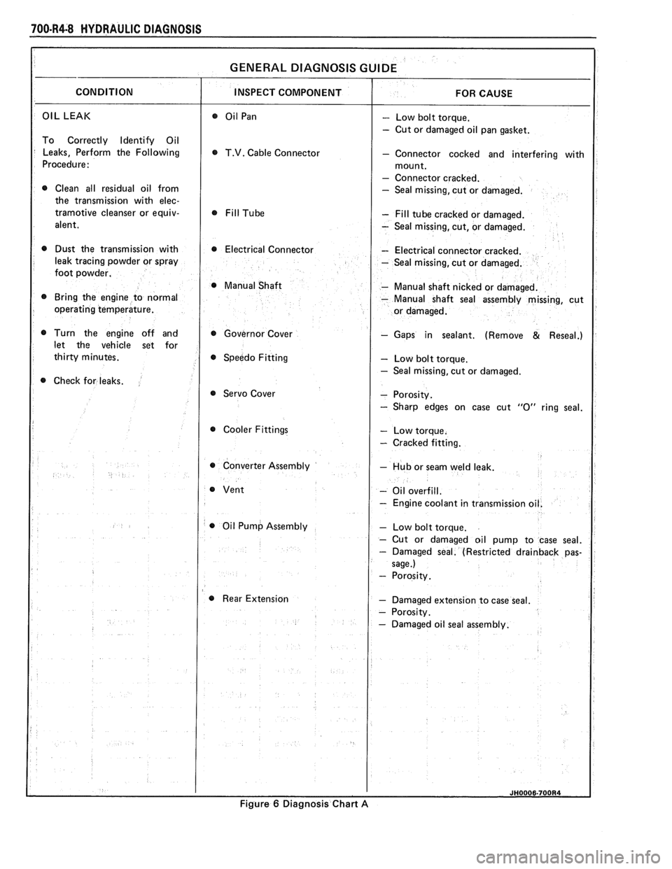
OIL LEAK - Low bolt torque.
- Cut or damaged oil pan gasket.
To Correctly Identify Oil
Leaks, Perform the Following
T.V. Cable Connector - Connector cocked and interfering with
Procedure:
- Connector cracked.
0 Clean all residual oil from - Seal missing, cut or damaged.
the transmission with
elec-
tramotive cleanser or equiv- - Fill tube cracked or damaged.
alent.
- Seal missing, cut, or damaged.
0 Dust the transmission with 0 Electrical Connector - Electrical connector cracked.
leak tracing powder or spray
- Seal missing, cut or damaged.
foot powder.
@ Manual Shaft - Manual shaft nicked or damaged.
Bring the engine to normal
- Manual shaft seal assembly missing, cut
operating temperature.
Turn the engine off and Governor Cover
- Gaps in sealant. (Remove & Reseal.)
let the vehicle set for
Speedo Fitting
- Low bolt torque.
- Seal missing, cut or damaged.
Check for leaks.
@ Servo Cover
Cooler Fittings
- Cracked fitting.
0 Converter Assembly - Hub or seam weld leak.
- Oil overfill.
- Engine coolant in transmissio
0 Oil Pump Assembly
Rear Extension
- Damaged extension to case seal.
Figure
6 Diagnosis Chart A
Page 1050 of 1825
TORQUE CONVERTER CLUTCH (TCC)
DIAGNOSIS
To properly diagnose the Torque Converter
Clutch (TCC) system, perform all electrical
testing first and then the hydraulic testing. Refer
to the Torque Converter Section
6E2-C8 for
additional information.
The TCC is applied by fluid pressure which is
controlled by a solenoid located inside the Automatic
Transmission assembly. The solenoid is energized or
released by making or breaking an electrical circuit
through a combination of switches and sensors.
TCC Electrical Diagnosis
e For electrical diagnosis of TCC, refer to the
specific vehicle section in Section
8A, Electrical
Diagnosis.
e For diagnosis of emission control related
components of TCC, Refer to the specific section
of
6E, Driveability and Emissions.
e For the diagnosis of TCC Hydraulic Controls,
refer to the Procedure and Wiring Diagrams
provided in this section.
Functional Check Procedure
rn Inspect
1. Install a tachometer
2. Operate the vehicle until proper operating
temperature is reached
3. Drive vehicle at 50-55 mph (80-88 Km/h) with
light throttle (road load)
4. Maintaining throttle lightly touch the brake
pedal and check for a slight bump when the TCC
releases and a slight increase in engine RPM.
5. Release the brake, slowly accelerate and check for
a re-apply of the converter clutch and a slight
decrease in engine RPM.
Preliminary Checking Procedure
The purpose of the preliminary checking
procedure is to isolate external (electrical) problems
from internal (electrical or mechanical) ones.
Important
e Use only a scale type ohmmeter. High impedance
type ohmmeters and those with a digital readout
will not work.
e An ALCL scanner may be used to verify the
electrical circuit. Remember, a completed circuit
does not indicate that the solenoid will apply.
e Do not bench test using an automotive type
battery. Accidentally crossed wires will damage
the internal diodes of the TCC solenoid.
HYDRAULIC DIAGNOSIS 700-R4-61
External Controls
rn Inspect
e Connect voltmeter between transmission
connector and ground.
e Turn key "ON"
e If 0 or low voltage is found, refer to Sections 6E
and 8A for electrical diagnosis.
e If 12 volts are present at the connector, refer to
the TCC hydraulic diagnosis.
TORQUE CONVERTER EVALUATION
Torque Converter Stator
The Torque Converter Stator roller clutch can
have one of two different type malfunctions:
A. Stator Assembly freewheels in both
directions.
B. Stator Assembly remains locked up at all
times.
Condition A-Poor Acceleration Low Speed
The vehicle tends to have poor acceleration from
a standstill. At speeds above 30-35 mph (50-55
km/h),
the car may act normal. If poor acceleration is noted,
it should first be determined that the exhaust system
is not blocked, the engine timing is correct and the
transmission is in first
(1st) gear when starting out.
If the engine freely accelerates to high
r.p.m. in
"NEUTRAL" (N), it can be assumed that the engine
and exhaust system are normal. Checking for poor
performance in "Drive" and Reverse will help
determine if the stator is freewheeling at all times.
Condition B-Poor Acceleration High Speed
Engine r.p.m. and car speed limited or restricted
at high speeds. Performance when accelerating from a
standstill is normal. Engine may over-heat. Visual
examination of the converter may reveal a blue color
from over-heating.
If the converter has been removed, the stator
roller clutch can be checked by inserting a finger into
the splined inner race of the roller clutch and trying to
turn the race in both directions. The inner race should
turn freely clockwise, but not turn or be very difficult
to turn counterclockwise.
The Converter Should Be Replaced If:
e Leaks externally, such as at the hub weld area.
e Converter has an imbalance which cannot be
corrected. (Refer to Converter Vibration Test
Procedure).
e Converter is contaminated with engine coolant
containing antifreeze.
The Converter Should Not Be Replaced If:
e The oil has an odor, is discolored, and there is no
evidence of metal or clutch facing particles.
e The threads in one or more of the three converter
bolt holes are damaged.
- Correct with thread insert. (Refer to Section
6A).
Page 1054 of 1825
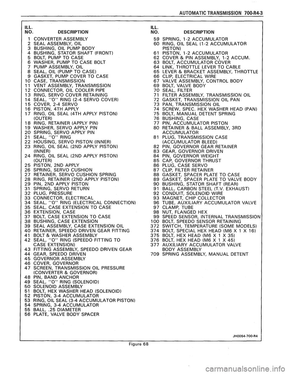
AUTOMAT lC TRANSMISSION 700-R4-3
ILL. NO. DESCRIPTION
1 CONVERTER ASSEMBLY
2 SEAL ASSEMBLY, OIL
3 BUSHING, OIL PUMP BODY
4 BUSHING, STATOR SHAFT (FRONT)
5 BOLT, PUMP TO CASE
6 WASHER, PUMP TO CASE BOLT
7 PUMP ASSEMBLY, OIL
8 SEAL, OIL (PUMP TO CASE)
9 GASKET, PUMP COVER TO CASE
10 CASE, TRANSMISSION
11 VENT ASSEMBLY, TRANSMISSION
1 12 CONNECTOR, OIL COOLER PIPE 13 RING, SERVO COVER RETAINING
14 SEAL, "0" RlNG
(2-4 SERVO COVER)
15 COVER, 2-4 SERVO
16 PISTON, 4TH APPLY
17 RING, OIL SEAL
(4TH APPLY PISTON)
(OUTER)
18 RING, RETAINER (APPLY PIN)
19 WASHER, SERVO APPLY PIN
20 SPRING, SERVO APPLY PIN
21 SEAL,
"0" RlNG
22 HOUSING, SERVO PISTON (INNER)
23 RING, OIL SEAL
(2ND APPLY PISTON)
(INNER)
24 RING, OIL SEAL
(2ND APPLY PISTON)
(OUTER)
25 PISTON, 2ND APPLY
26 SPRING, SERVO CUSHION
27 RETAINER, SERVO CUSHION SPRING
28 RING, RETAINER
(2ND APPLY PISTON)
29 PIN, 2ND APPLY PISTON
31 SPRING, SERVO RETURN
32 PLUG, PRESSURE
33 CONNECTOR, ELECTRICAL
34 SEAL,
"0" RlNG (ELECTRICAL CONNECTION)
35 SEAL, CASE EXTENSION TO CASE
36 EXTENSION, CASE
37 BOLT, CASE EXTENSION TO
CASE 38 BUSHING, CASE EXTENSION
39 SEAL ASSEMBLY, CASE EXTENSION OIL
40 RETAINER, SPEEDO DRIVEN GEAR FITTING
41 BOLT
& WASHER ASSEMBLY
42 SEAL, "0" RlNG (SPEEDO FITTING TO
CASE EXTENSION)
43 FITTING ASSEMBLY, SPEEDO DRIVEN GEAR
44 GEAR, SPEEDO DRIVEN
45 GOVERNOR ASSEMBLY
46 COVER, GOVERNOR
47 SCREEN, TRANSMISSION OIL PRESSURE
(CONVERTER
81 GOVERNOR)
48 PIN, BAND ANCHOR
49 SEAL,
"0" RlNG (SOLENOID)
50 SOLENOID ASSEMBLY
51 BOLT, HEX WASHER HEAD (SOLENOID)
52 PISTON, 3-4 ACCUMULATOR
53 RING, OIL SEAL
(3-4 ACCUMULATOR PISTON)
54 SPRING, 3-4 ACCUMULATOR
55 BALL,
.25 DIAMETER 56 PLATE, VALVE BODY SPACER
ILL. NO. DESCRIPTION
59 SPRING, 1-2 ACCUMULATOR
60 RING, OIL SEAL (1
-2 ACCUMULATOR
PISTON)
61 PISTON, 1-2 ACCUMULATOR
62 COVER
& PIN ASSEMBLY, 1-2 ACCUM.
63 BOLT, ACCUMULATOR COVER
64 LINK, THROTTLE LEVER TO CABLE
65 LEVER
& BRACKET ASSEMBLY, THROTTLE
66 CLIP, ELECTRICAL WIRE
67 VALVE ASSEMBLY, CONTROL BODY
69 BOLT, VALVE BODY
70 SEAL, FILTER
71 FILTER ASSEMBLY, TRANSMISSION OIL
72 GASKET, TRANSMISSION OIL PAN
73 PAN, TRANSMISSION OIL
74 SCREW, SPEC. HEX WASHER HEAD (PAN)
75 BOLT, MANUAL DETENT SPRING
76 BUSHING, CASE
77 PIN, ACCUMULATOR PISTON
80 RETAINER
& BALL ASSEMBLY, 3RD
ACCUMULATOR
81 PLUG, TRANSMISSION CASE
(ACCUMULATOR BLEED)
82 PIN, GOVERNOR GEAR RETAINER
83 GEAR, GOVERNOR DRIVEN
84 PIN, GOVERNOR WEIGHT
85 CAP, GOVERNOR THRUST
86 PLUG, CASE SERVO
87 CLIP, FILTER RETAINER
88 GASKET, SPACER PLATE TO CASE
89 GASKET, SPACER PLATE TO VALVE BODY
90 BUSHING, STATOR SHAFT
(REAR)
91 BALL, CARBON STEEL (T.V. EXHAUST)
92 CONDUIT, SOLENOID WIRE
93 MAGNET, CHIP COLLECTOR
96 TUBE, AUXILIARY ACCUMULATOR VALVE
97 CLAMP, TUBE
98 NUT, FLANGED HEX
99 SPEED SENSOR, INTERNAL
TRANSMISSIOr 100 BOLT, SPEEDO SENSOR RETAINING
372 SWITCH, TEMPERATURE (SOME MODELS)
374 BOLT, SPECIAL HEX HEAD (M6 X
1 X 16)
375 BOLT, HEX HEAD (M6 X 1 X
35) 376 BOLT, HEX HEAD (M6 X 1 X 45)
377 AUXILIARY ACCUMULATOR VALVE
BODY ASSEMBLY
709 SPRING ASSEMBLY, MANUAL DETENT
Figure 68
Page 1121 of 1825
7A1-2 AUTOMATIC TRANSMISSION ON-VEHICLE SERVICE
Pitting
FLEXPLATE/TORQUE CONVERTER VIBRATION
TEST PROCEDURE
1. Start engine
2. With engine at idle speed and the transmission in
"Park"
(P) or "Neutral" (N), observe vibration.
3. Shut off engine.
Remove or Disconnect
e Flexplate cover attaching bolts
s Flexplate to torque converter attaching
bolts
e Rotate torque converter 120 (1/3 turn)
Install
or Connect
e Flexplate to torque converter attaching
bolts
- Torque bolts to 47 N.m (35 Ibs. ft.)
s Flexplate cover bolts
- Torque bolts to 6 N-m (53 lbs. in.)
4. Start engine and check for vibration. Repeat this
procedure un
ti1 the best possible balance is
obtained.
NOTICE: Some engine/transmission
combinations cannot be balanced in this manner
due to limited clearances between the torque
converter bolts and engine. Be sure bolts do not
bottom out in lug nuts or the torque converter
cover could be dented and cause internal damage.
FLUID LEAK DIAGNOSIS
The cause of most external leaks can generally be
located and repaired with the transmission in the car.
METHODS FOR LOCATING LEAKS
General Method
s Verify that the leak is transmission fluid.
a Thoroughly clean the suspected leak area.
s Operate the car for about 15 miles or until normal
operating temperatures are reached.
e Park the car over clean paper or cardboard.
s Shut off engine and look for fluid spots on paper.
a Make necessary repairs.
Powder Method
e Thoroughly clean the suspected leak area with
solvent.
a Apply an aerosol type powder (foot powder) to
the suspected leak area.
s Operate the car for about 15 miles or until normal
operating temperatues are reached.
s Shut off engine.
e Inspect suspected leak area and trace the leak
path through the powder to find the source.
a Make necessary repairs.
Dye And Black Light Method
A fluid dye and black light kit is available from
various tool manufacturers.
s Follow the manufacturer's recommendations for
the amount of dye to be used.
a Detect the leak with the black light.
e Correct cause of leak.
REPAIRING THE LEAK
Once the leak has been pinpointed and traced
back to its source, the cause of the leak must be
determined in order for it to be repaired properly. If a
gasket is replaced, but the sealing flange is bent, the
new gasket will not repair the leak. The bent flange
must be repaired also. Before attempting to repair a
leak, check to be sure that the following conditions are
correct as they may cause a leak.
Gaskets
s Fluid level/pressure is too high.
e Plugged vent or drain-back holes.
s Improperly torqued fasteners or dirty/damaged
threads.
a Warped flanges or sealing surface.
e Scratches, burrs or other damage to the sealing
surface.
e Damaged or worn gasket.
e Cracking or porosity of the component.
s Improper sealant used (where applicable).
Seals
e Fluid level/pressure is too high.
a Plugged vent or drain-back holes.
s Damaged seal bore (scratched, burred or nicked).
e Damaged or worn seal.
e Improper installation.
a Cracks in component.
e Manual or output shaft surface scratched, nicked
or damaged.
a Loose or worn bearing causing excess seal wear.
Possible Points of Oil Leak
I. Transmission/Transmission oil pan :
Attaching bolts not correctly torqued
s Improperly installed or damaged gasket
s Oil pan or mounting face not flat
2, Case Leak :
@ Filler pipe "multi-lip seal" damaged or
missing
a Filler pipe bracket mislocated
s T.V. cable "multi-lip" seal missing,
damaged or improperly installed
a Governor cover or "0" ring damaged or
missing
@ Speedometer driven gear/speed sensor seal
damaged
e Manual shaft seal damaged
s Oil cooler connector fittings loose or
damaged
Page 1122 of 1825
AUTOMATIC TMNSMISSION ON-VEHICLE SERVICE 7A1-3
e Propeller shaft oil seal worn or damaged
o Governor cover
e Line pressure pipe plug loose
@ Porous casting
3. Leak at converter end:
Converter seal damaged
- Seal lip cut. (Check converter hub for
damage.)
- Bushing moved forward and damaged
- Garter spring missing from seal
o Converter leak in weld area. (Refer to
Torque Converter.)
Porous casting (Case or pump)
4. Fluid comes out vent pipe or fill tube:
Over-filled
Water or coolant in fluid. Fluid will appear
milky.
e Case porous
e Incorrect fluid level indicator
e Plugged vent
e Drain back holes plugged
Mispositioned oil pump to case gasket (if
equipped)
Case Porosity Repair
1. Clean the leak area with solvent and air dry.
CAUTION: Epoxy adhesive may cause
skin irritations and eye damage. Read
and follow all information on the
container label as provided by the
manufacturer.
2. Mix a sufficient amount of epoxy adhesive,
# 1052533, or equivalent, following the
manufacturer's recommendations.
3. While the transmission case is hot, apply epoxy
adhesive with a clean, dry soldering acid brush.
4. Allow the epoxy adhesive to cure for three hours
before starting the engine.
5. Repeat fluid leak diagnosis procedures.
TORQUE CONVERTER CLUTCH ELECTRICAL
CONTROLS
The Torque Converter Clutch (TCC) system uses
controls that are internal as well as external to the
transmission. For internal control components of the
TCC system, refer to the I-Iydraulic Diagnosis Section
for for wiring diagrams and switch locations.
The external control components of the TCC
system include:
1. Brake Release Switch - To avoid stalling the
engine when braking, the converter clutch is
released any time the brakes are applied.
2. Electronic Control ModuOe - Receives input
signals and grounds TCC solenoid to apply clutch
when proper operating conditions are met.
3. Throttle Position Sensor - Sends throttle
position information to Electronic Control
Module.
4. Vacuum Sensor - Sends engine vacuum (load)
information to Electronic Control Module.
5. Vehicie Speed Sensor - Sends vehicle speed
information to Electronic Control Module.
6. Coolant Temperature Sensor - Sends engine
coolant temperature information to Electronic
Control Module.
TORQUE CONVERTER CLUTCH DIAGNOSIS
To properly diagnose the Torque Converter
Clutch (TCC) system perform all electrical testing first
and then the hydraulic testing. Refer to the appropriate
Driveability and Emissions Section (6E) for additional
Torque Converter Clutch Information
ON-VEHICLE SERVICE
SI-IIFT CONTROL CABLE
Remove or Disconnect (Fig. 1)
1. Negative battery cable.
2. Raise car, see Section OA.
3. Cable attachments at transmission.
4. Lower car.
5. Console, see Section
8C.
6. Cable at control lever and base.
7. Cable from floor.
install or Connect
1. Cable to floor.
2. Cable at base and control lever.
3. Console, see Section 8C.
4. Place control lever in "NEUTRAL"
5. Raise car.
6. Cable attachments at transmission.
7. Adjust cable.
8. Lower car.
9. Negative battery cable.
Adjust (Fig. 1)
1. Place control lever in "N" (Neutral).
2. Raise car, see Section 0.4.
3. Loosen cable
attachment at shift lever.
4. Rotate shift lever "clockwise" to park detent and
then back to neutral.
5. Tighten cable attachment.
15
N-m (11 lbs. ft.)
Important
Levg must be held out of "PARK" when
torquing nut.
6. Lower car.
7. Check cable adjustment by rotating control lever
thru the detents.
Remove or Disconnect (Fig. 2)
1. Negative battery cable.
2. Console, see Section 8C.
3. Cable at control lever and base.