1988 PONTIAC FIERO oil temperature
[x] Cancel search: oil temperaturePage 797 of 1825
CONNECTOR
TO ALTERNATOR
I.P.CONNECTOR
DK GRNNVHT 335
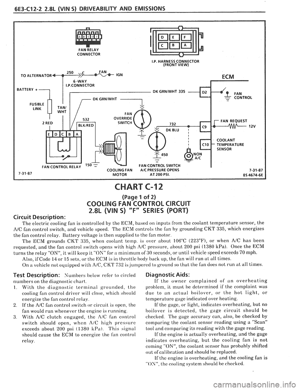
CHART C-12
(Page 1 of 2)
COOLING FAN CONTROL CIRCUIT
2.8L (VIN S) "F" SERIES (PORT)
Circuit Description:
'I'he electric cooling fan is controlled by the ECM, based on inputs from the coolant temperature sensor, the
NC fan control switch, and vehicle speed. 'I'he ECM controls the f~in by grounding CKT 335, which energizes
the fan control relay. Battery voltage is then supplied to the fan motor.
The ECM grounds
CKT 335, when coolant temp. is over about 106°C (223"F), or when AIC has been
requested, and the fan control switch opens with high
I\/C pressure, about 200 psi (1380 kPa). Once the ECM
turns the relay "ON", it will keep it "ON" for a nlinirnum of GO seconds, or until vehicle speed exceeds 70 mph.
Also, if Code
14 or 15 sets, or the ECM is in throttle body back up, the fan will run at all times.
On
kt vehicle not equipped with A/C, CK'I' 732 is,ju~rlperetl to ground so that Lhe fan does not run at all times.
Test Description: Numbers below refer to circled
numbers on the diagnostic chart,.
1. With the diagnostic terminal grounded, the
cooling
fan control driver will close, which should
energize the fan control
relay.
2. If the A/C fan control switch or circuit is open, the
fan would run whenever the engine is running.
3. With AIC clutch engaged, the i\lC fan control
switch should open, when
A/C high pressure
exceeds about
200 psi ( 1380 k13a). This signal
should cause the
ECM to energize the ran control
relay.
Diagnostic Aids:
If the owner complained of an overheating
problem, it
rnust he determined if the complaint was
clue to an actuill hoilover, or the hot light, or
temperature gage indicated over heating.
If the gage, or light, indicates overheating, but no
hoilover is detected, the gage circuit should he
checked.
'I'he gage accuracy can, also, be checked by
comparing the coolant sensor reading using a "Scan"
tool and comparing its reading with the gage reading.
If the engine is actually overheating, and the gage
indicates overheating, but the cooling fan is not
coming "ON", the coolant sensor has probably shifted
out
ofcalibration and should be replaced.
If
the engine is overheating, and the cooling fan is
"ON", the cooling system should hc checked.
Page 805 of 1825
6E3-A-2 5.OL (VIN F) & 5.7L(VIN 8) DRIVEABILITY AND EMISSIONS
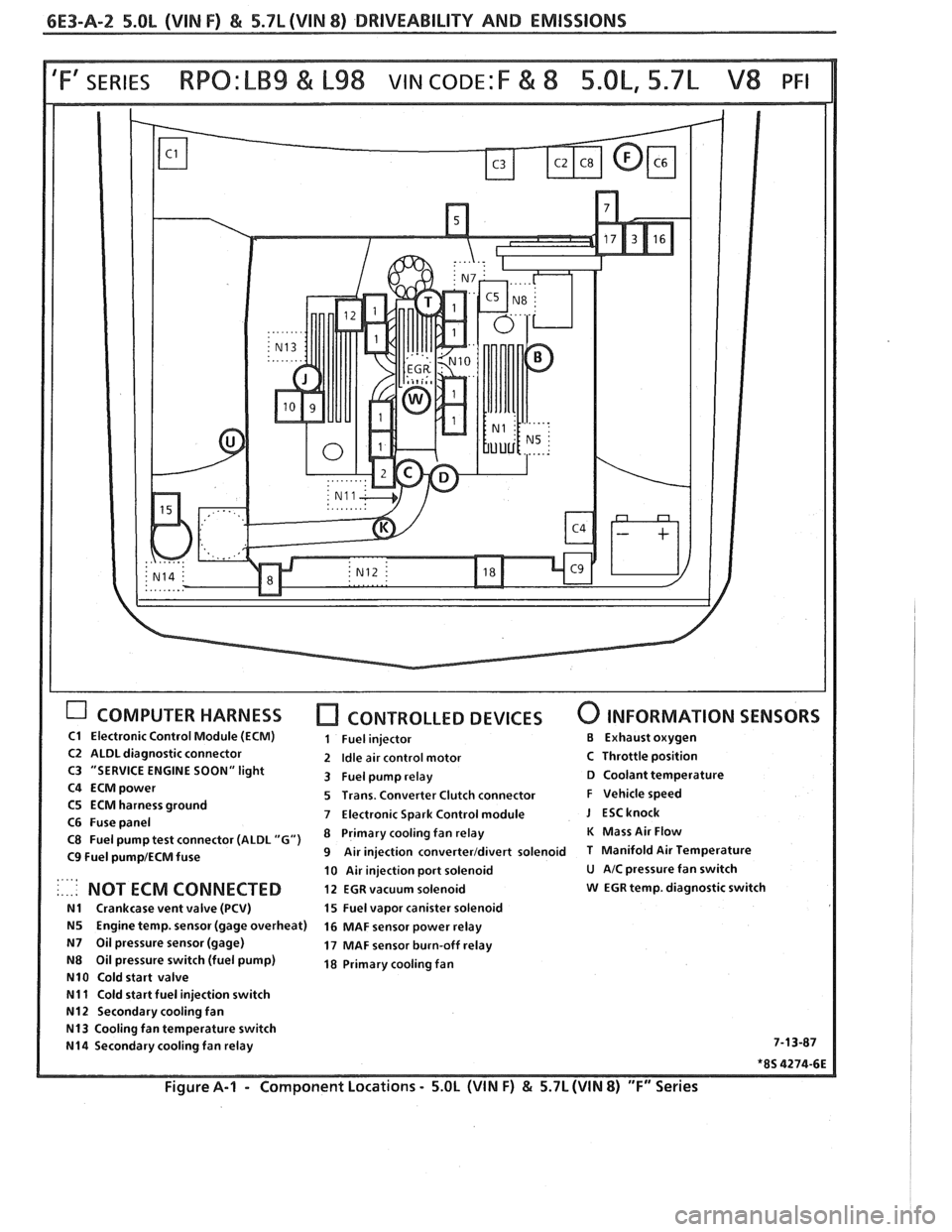
COMPUTER HARNESS [7 CONTROLLED DEVICES 0 INFORMATION SENSORS
C1 Electronic Control Module (ECM) 1 Fuel injector €3 Exhaust oxygen
C2 ALDL diagnostic connector 2 Idle air control motor C Throttle position
C3 "SERVICE ENGINE SOON" light
3 Fuel pump relay D Coolant temperature
C4
ECMpower 5 Trans. Converter Clutch connector F Vehicle speed
C5 ECM harness ground
7 Electronic Spark Control module J ESCknock C6 Fuse panel
C8 Fuel pump test connector (ALDL "G") Primary fan relay K Mass Air Flow
C9 Fuel pump1ECM fuse 9 Air injection converterldivert solenoid T Manifold Air Temperature
10 Air injection port solenoid
U AIC pressure fan switch . ., .. .. NOT ECM CONNECTED 12 EGR vacuum solenoid w EGR temp. diagnostic switch
N1 Crankcase vent valve (PCV) 15 Fuel vapor canister solenoid
N5 Engine temp. sensor (gage overheat)
16 MAF sensor power relay
N7 Oil pressure sensor (gage) 17 MAF sensor burn-off relay
N8 Oil pressure switch (fuel pump) 18 Primary cooling fan
N10 Cold start valve
N11 Cold start fuel injection switch
N12 Secondary cooling fan
N13 Cooling fan temperature switch
N14 Secondary cooling fan relay 7-13-87
*8S 4274-6E
Figure A-I - Component
Locations - 5.OL (WIN F) & 5.7L (WIN 8) "F" Series
Page 867 of 1825
6E3-B-2 5.OL (VIN F) & 5.7L (VIN 8) DRIVEABILITY AND EMISSIONS
Problem may or may not turn "ON" the "Service Engine Soon" light, or store a code.
DO NOT use the Trouble Code Charts in
An intermittent "Service Engine Soon" light
Section A for intermittent problems. The fault must
with no stored code may be caused by:
be present to locate the problem. If a fault is
@ Ignition coil shorted to ground and arcing at
intermittent, use of Trouble Code Charts
may result
spark plug wires or plugs.
in replacement of good parts.
"Service Engine Soon" light wire to
ECM
@ Most intermittent problems are caused by
shorted to ground. (CKT 419).
faulty electrical connections or wiring. Perform
Diagnostic "Test" Terminal wire to ECM,
careful check as described at start of Section
shorted to
ground.(CKT 451)
"B". Check for:
@ ECM power grounds. See ECSI wiring
@ Poor mating of the connector halves, or diagrams.
terminals not fully seated in the connector
@ Loss of trouble code memory. To check,
body (backed out). disconnect TPS and idle engine until "Service
@ Improperly formed or damaged terminals.
Engine Soon" light comes on. Code 22 should be
All connector terminals in problem circuit
stored, and kept in memory when ignition is
should be carefully reformed or replaced to turned "OFF". If not, the ECM is faulty.
insure proper contact tension.
@ Check for an electrical system interference
@ Poor terminal to wire connection. This caused by a defective relay, ECM driven
requires removing the terminal from the
solenoid, or switch. They can cause a sharp
connector body to check. See "Introduction"
electrical surge. Normally, the problem will
to Section
"6E". occur when the faulty component is operated.
@ If a visual check does not find the cause of the @ Check for improper installation of electrical
problem, the car can be driven with a voltmeter
options, such as lights,
%way radios, etc.
connected to
a suspected circuit. A "Scan" tool
EST wires should be kept away from spark plug
can also be used for monitoring input signals to wires, distributor wires, distributor housing,
the ECM to help detect intermittent conditions. coil, and generator. Wire from
ECM to
An abnormal voltage, or "Scan" reading, when distributor
(CKT 453) should be a good
the problem occurs, indicates the problem
may connection.
be in that circuit. If the wiring and connectors
@ Check for open diode across AIC compressor
check OK and a Trouble Code was stored for a
clutch, and for other open diodes (see wiring
circuit having a sensor, except for Codes
43, 44, diagrams).
and 45, substitute a known good sensor and
recheck.
HARD START
Definition: Engine cranks OK, but does not start for a long
time. Does eventually run, or may start but immediately dies.
Perform careful check as described at start of
Section
"B".
@ Make sure driver is using correct starting
procedure.
@ CHECK:
- TPS for sticking or binding or a high TPS
voltage with the throttle closed (should read
less than
.700 volts).
- High resistance in coolant sensor circuit or
sensor itself. See Code 15 chart or with
a
"Scan" tool compare coolant temperature with
ambient temperature on a cold engine.
- Fuel pressure CHART A-7.
- Water contaminated fuel.
- EGR operation. Be sure valve seats properly and
is not staying open. See CHART C-7.
- Both injector fuses (visually inspect).
- Ignition system - Check distributor for:
Proper Output with ST-125.
Worn shaft.
Bare and shorted wires.
Pickup coil resistance and connections.
Loose ignition coil ground.
Moisture in distributor cap.
@ If problem exists in cold weather, check cold start
valve. See CHART A-9.
Page 907 of 1825
6E3-C2-20 5.0L (VIN F) & 5.7L (WIN 8) DRIVEABILITY AND EMISSIONS
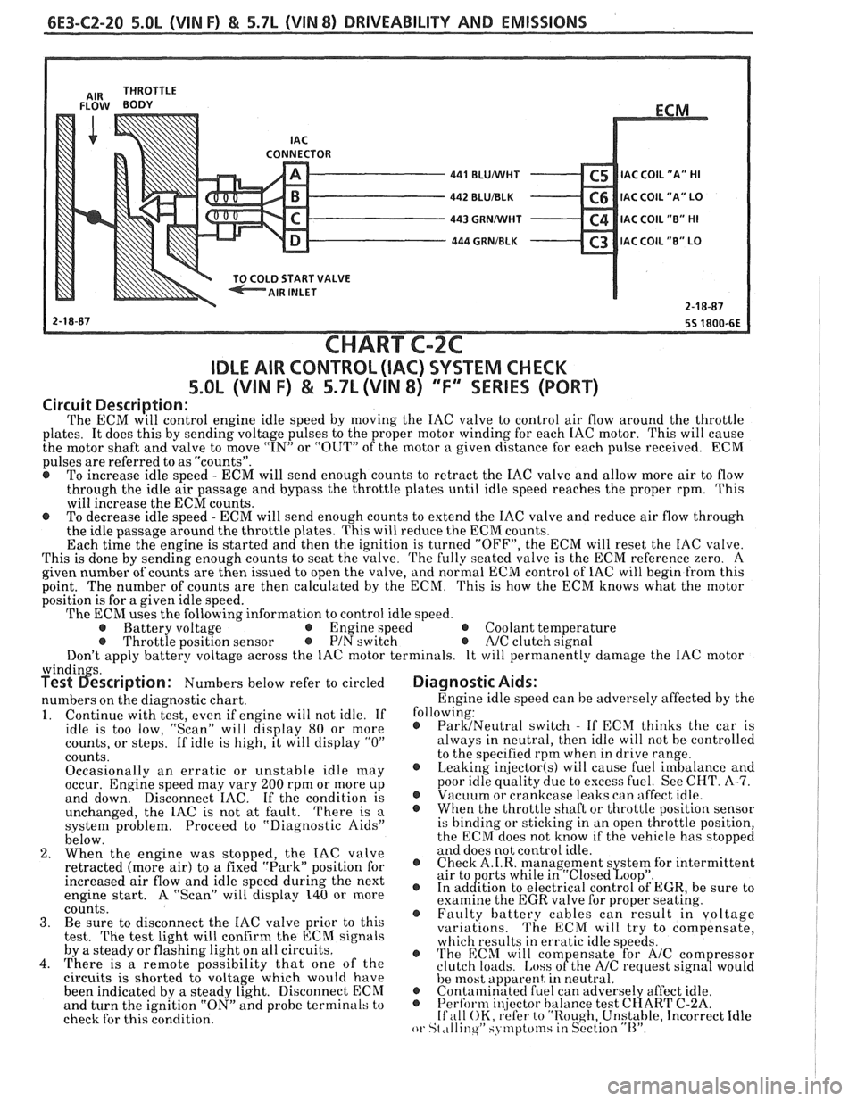
CONNECTOR - 441 BLUMlHT C5 IAC C0lL1'A" HI - 442 BLUIBLK C6 IAC COIL "A" LO - 443 GRNMlHT C4 IAC COIL "B" HI - 444 GRNIBLK C3 lAC COIL "B" LO v
START VALVE
CHART C-2C
IDLE AIR CONTROL (IAC) SYSTEM CHECK
S.OL (VIN F) & 5.7L (VIN 8) "F'" SERIES (PORT)
Circuit Description:
The ECM will control engine idle speed by moving the IAC valve to control air flow around the throttle
plates. It does this by sending voltage pulses to the proper motor winding for each IAC motor. This will cause
the motor shaft and valve to move
"IN" or "OUT" of the motor a given distance for each pulse received. ECM
pulses are referred to as "counts".
@ To increase idle speed - ECM will send enough counts to retract the IAC valve and allow more air to flow
through the idle air passage and bypass the throttle plates until idle speed reaches the proper rpm. This
will increase the ECM counts.
e To decrease idle speed - ECM will send enough counts to extend the IAC valve and reduce air flow through
the idle passage around the throttle plates. This will reduce the ECM counts.
Each time the engine is started and then the ignition is turned "OFF", the ECM will reset the IAC valve.
This is done by sending enough counts to seat the valve.
The fully seated valve is the ECM reference zero. A
given number of counts are then issued to open the valve, and normal ECM control of IAC will begin from this
point. The
number of counts are then calculated by the ECM. This is how the ECM knows what the motor
position is for a given idle speed.
The ECM uses the following information to control idle speed.
@ Battery voltage @ Engine speed @ Coolant temperature @ Throttle position sensor @ PIN switch e A/C clutch signal
Don't apply battery voltage across the IAC motor terminals. It will permanently damage the IAC motor
windin s. Test 6escription: Numbers below refer to circled
numbers on the diagnostic chart.
1. Continue with test, even if engine will not idle. If
idle is too low, "Scan" will display 80 or more
counts, or steps. If idle is high, it will display
"0"
counts.
Occasionally an erratic or unstable idle
[nay occur. Engine speed may vary 200 rpm or more up
and down. Disconnect IAC. If the condition is
unchanged, the IAC is not at fault.
There is a
system problem. Proceed to "Diagnostic Aids"
below.
2. When the engine was stopped, the IAC valve
retracted (more air) to
a fixed "Park" position for
increased air flow and idle speed during the next
engine start. A "Scan" will display 140 or more
coiints. 3. Be sure to disconnect the IAC valve prior to this
test.
The test light will confirm the ECM signals
by a steady or flashing light on all circuits.
4. There is a remote possibility that one of the
circuits is shorted to voltage which would have
been indicated by a steady light. Disconnect ECM
and turn the ignition "ON" and probe terminals to
check for this condition.
Diagnostic Aids:
Engine idle speed can be adversely affected by the
following:
@ ParMNeutral switch - If ECM thinks the car is
always in neutral, then idle will not be controlled
to the specified rpm when in drive range.
@ Leaking injector(s) will cause fuel imbalance and
poor idle quality due to excess fuel. See CHT.
A-7. @ Vacuum or crankcase leaks can affect idle. @ Whenthethrottleshaftorthrottlepositionsensor
is binding or sticking in an open throttle position,
the ECM does not know if the vehicle has stopped
and does not control idle.
@ Check A.I.R. management s stem for intermittent
air to orts while in "~losed~oo~". @ In ad&tion to electrical control of EGR, be sure to
examine the EGR valve for proper seating.
@ Faulty battery cables can result in voltage
variations. The ECM will try to compensate,
which results in erratic idle speeds.
@ 'I'he ECM will com ensate for A/C com ressor
clutch loacls. [.ass ofthe NC request sign8 would
he 11lost apparent, in neutral. @ Contalninatecl fuel can adverse1 affect idle. @ Perform i~!jector balance test C~ART C-2A. If ,111 OK, refer to "Rough, Unstable, Incorrect Idle or St ,tllinqW SJ tnptcfinsiin S~'ction "11''.
Page 929 of 1825
6E3-C6-2 5.OL (VIN F) & 5.7L (VIN 8) DRIVEABILITY AND EMISSIONS
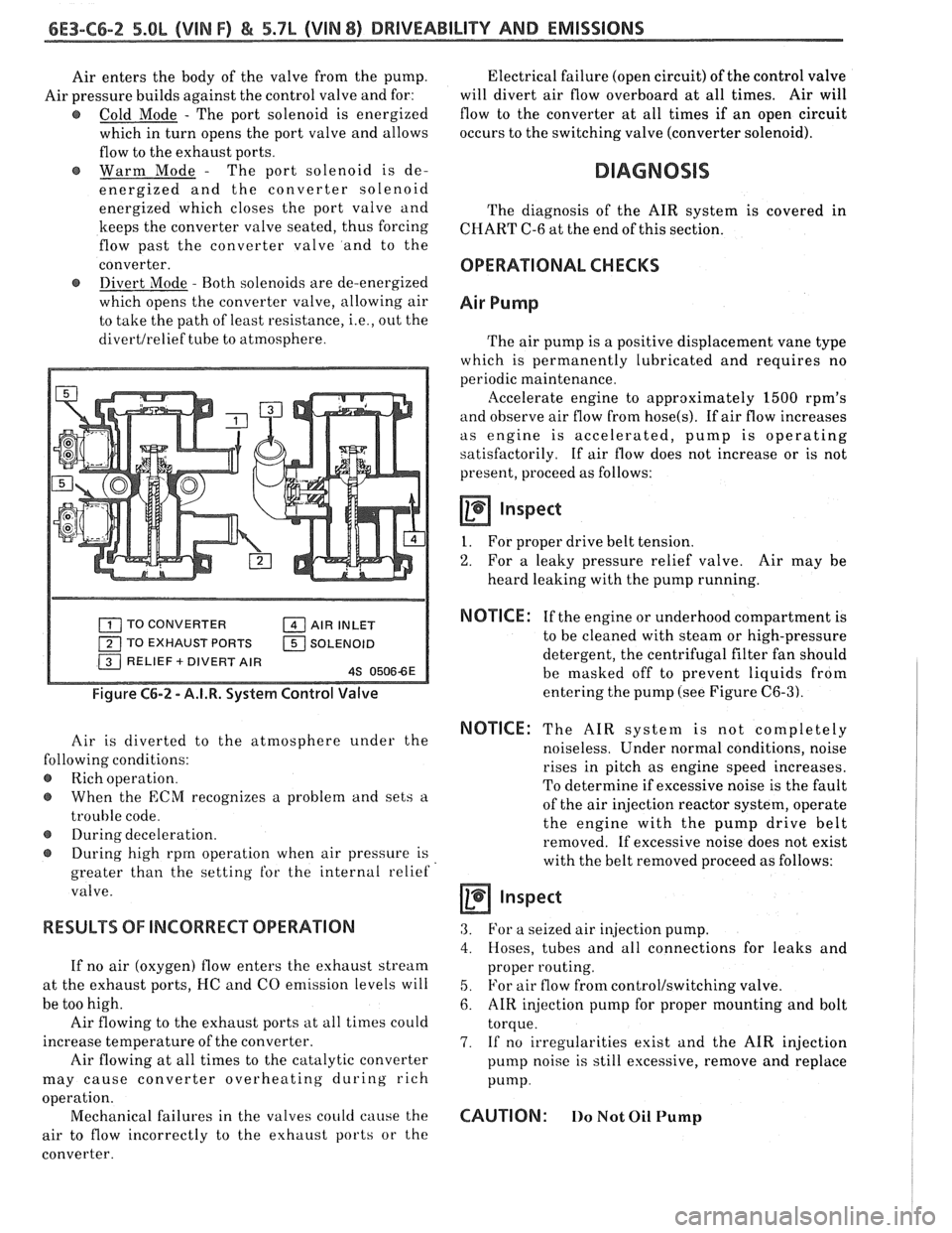
Air enters the body of the valve from the pump.
Air pressure builds against the control valve and for:
@ Cold Mode - The port solenoid is energized
which in turn opens the port valve and allows
flow to the exhaust ports.
Warm Mode
- The port solenoid is de-
energized and the converter solenoid
energized which closes the port valve and
keeps the converter valve seated, thus forcing
flow past the converter valve and to the
converter.
@ Divert Mode - Both solenoids are de-energized
which opens the converter valve, allowing air
to take the path of least resistance,
i.e., out the
divertlrelief tube to atmosphere. Electrical
failure (open circuit) of the control valve
will divert air flow overboard at all times. Air will
flow to the converter at all times if an open circuit
occurs to the switching valve (converter solenoid).
DIAGNOSIS
The diagnosis of the AIR system is covered in
CHART C-6 at the end of this section.
OPERATIONAL CHECKS
Air Pump
The air pump is a positive displacement vane type
which is permanently lubricated and requires no
periodic maintenance.
llccelerate engine to approximately 1500 rpm's
and observe air flow from hose(s). If air flow increases
as engine is accelerated, pump is operating
satisfactorily. If air flow does not increase or is not
present, proceed as follows:
Inspect
I. For proper drive belt tension.
2. For a leaky pressure relief valve. Air may be
heard leaking with the pump running.
TO CONVERTER AIR INLET
TO EXHAUST PORTS
1 SOLENOID
Figure C6-2 - A.I.R. System Control Valve
Air is diverted to the atmosphere under the
lowing conditions:
Rich operation.
When the
ECM recognizes a problem and sets a
trouble code.
@ During deceleration.
During high rprn operation when air pressure is
greater than the setting
for the internal relief
valve.
RESULTS OF INCORRECT OPERATION
If no air (oxygen) flow enters the exhaust stream
at the exhaust ports, I-IC and CO emission levels will
be too high.
Air flowing to the exhaust ports at all times could
increase temperature of the converter.
Air flowing at all times to the catalytic converter
may cause converter overheating during rich
a ion.
oper
t'
Mechanical failures in the valves could cause the
air to flow incorrectly to the exhaust ports or the
converter.
NOTICE : If the engine or underhood compartment is
to be cleaned with steam or high-pressure
detergent, the centrifugal filter fan should
be masked off to prevent liquids from
entering the pump (see Figure
C6-3).
NOTICE: The AIR system is not completely
noiseless. Under normal conditions, noise
rises in pitch as engine speed increases.
To determine if excessive noise is the fault
of the air injection reactor system, operate
the engine with the pump drive belt
removed. If excessive noise does not exist
with the belt removed proceed as follows:
a inspect
3. For a seized air injection pump.
4. Hoses, tubes and all connections for leaks and
proper routing.
5. For air flow from control/switching valve.
6. AIR injection pump for proper mounting and bolt
torque.
7. If no irregularities exist and the AIR injection
pump noise is still excessive, remove and replace
Pump.
CAUTION: 110 Not Oil Pump
Page 943 of 1825
6E3-C8-2 5.OL (VIN F) & 5.7L (VIN 8) DRIVEABILITY AND EMISSIONS
15-WAY I.P. CONNECTOR
VEHICLE SPEED SIGNAL
SPEED INPUT
4TH GEAR SIGNAL
422
TANIBLK
4TH GEAR SW.
TRANSMISSION ALDL CONNECTOR
TCC APPLY SOLENOID
CHART C-8A
(Page 1 of 2)
AUTOMATIC TRANSMISSION CONVERTER CLUTCH (TCC)
5.OL (VIN F) & 5.7L (VIN 8) "F'" SERIES (PORT)
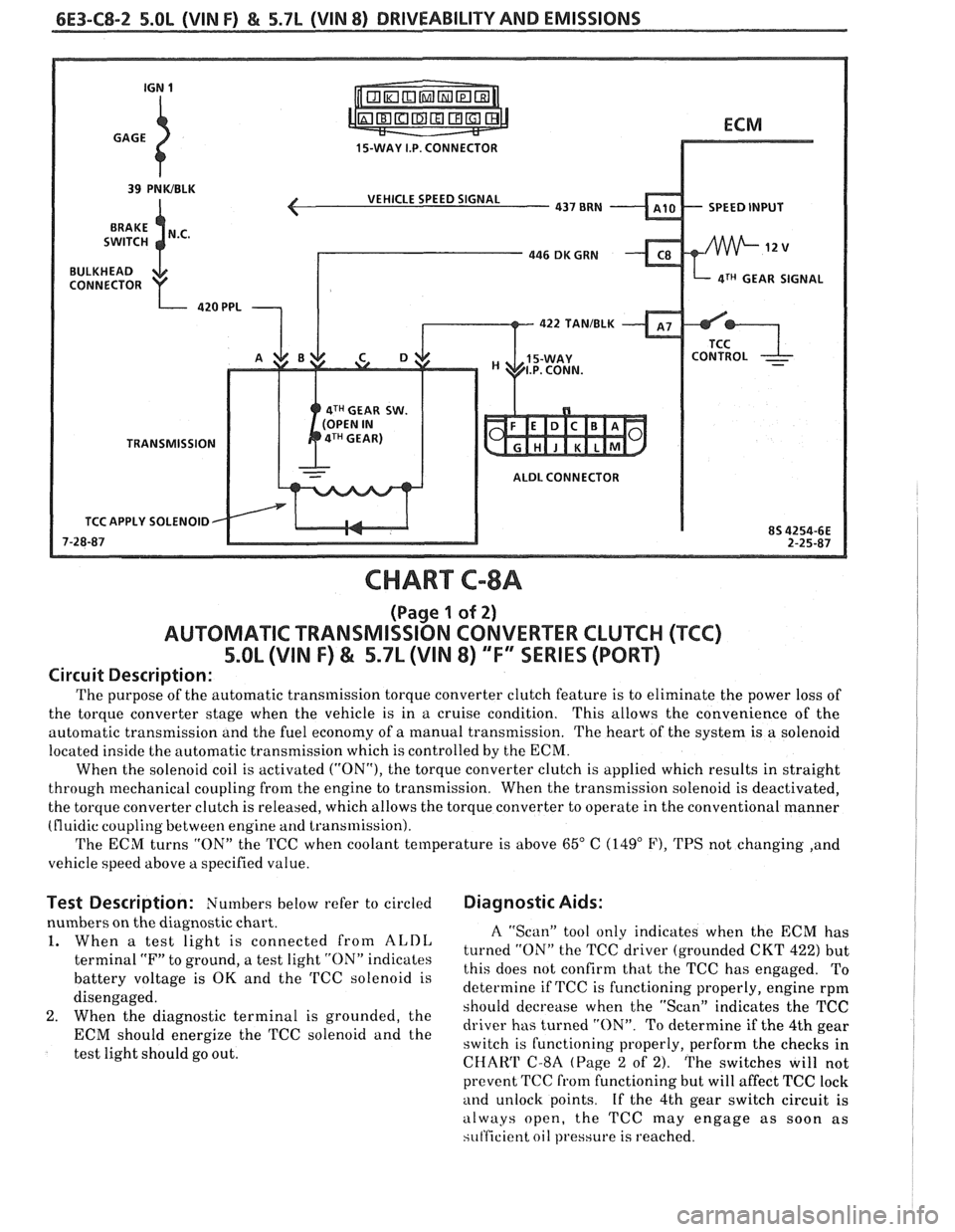
Circuit Description:
The purpose of the automatic transmission torque converter clutch feature is to eliminate the power loss of
the torque converter stage when the vehicle is in a cruise condition. This allows the convenience
of the
automatic transmission and the fuel economy of
a manual transmission. The heart of the system is a solenoid
located inside the automatic transmission which is controlled by the ECM.
When the solenoid coil is activated
("ON"), the torque converter clutch is applied which results in straight
through mechanical coupling from the engine to transmission. When the transmission solenoid is deactivated,
the torque converter clutch is released, which allows the torque converter to operate in the conventional manner
(fluidic coupling between engine
and transmission).
The ECM turns "ON" the TCC when coolant temperature is above
65" C (149" F), TPS not changing ,and
vehicle speed above
a specified value.
Test Description: Numbers below refer to circled Diagnostic Aids:
nbers on the diagnostic chart.
When
a test light is connected from ALDL
terminal "F" to ground, a test light "ON" indicates
battery voltage is
OK and the TCC solenoid is
disengaged.
When the diagnostic terminal is grounded, the
ECM should energize the TCC solenoid and the
test light should go out.
A "Scan" tool only indicates when the ECM has
turned "ON" the TCC driver (grounded CKT
422) but
this does not confirm that the TCC has engaged. To
determine if TCC is functioning properly, engine rpm
should decrease when the "Scan" indicates the TCC
driver has turned "ON". To determine if the 4th gear
switch is functioning properly, perform the checks in
CHAW C-8A (Page 2 of 2). The switches will not
prevent TCC
from functioning but will affect TCC lock
and unlock points. If the 4th gear switch circuit is
always open, the TCC may engage as soon as
si~t'ficient oil pressure is reached.
Page 951 of 1825
6E3-C12-2 5.OL (VIN F) & 5.7b (VIN 8) DRIVEABILITY AND EMISSIONS
FAN CONTROL
RELAY CONN.
DK GRNNVHT 335
TEMPERATURE
SENSOR SIGNAL.
TURNS ON PRIMARY
FAN AT
223OF (1 06'C)
CHART C-12
(Page 1 of 2)
COOLING FAN CONTROL CIRCUIT
5.8L (VIN F) & 5.7L (VIN 8) "F" SSERlES (PORT)
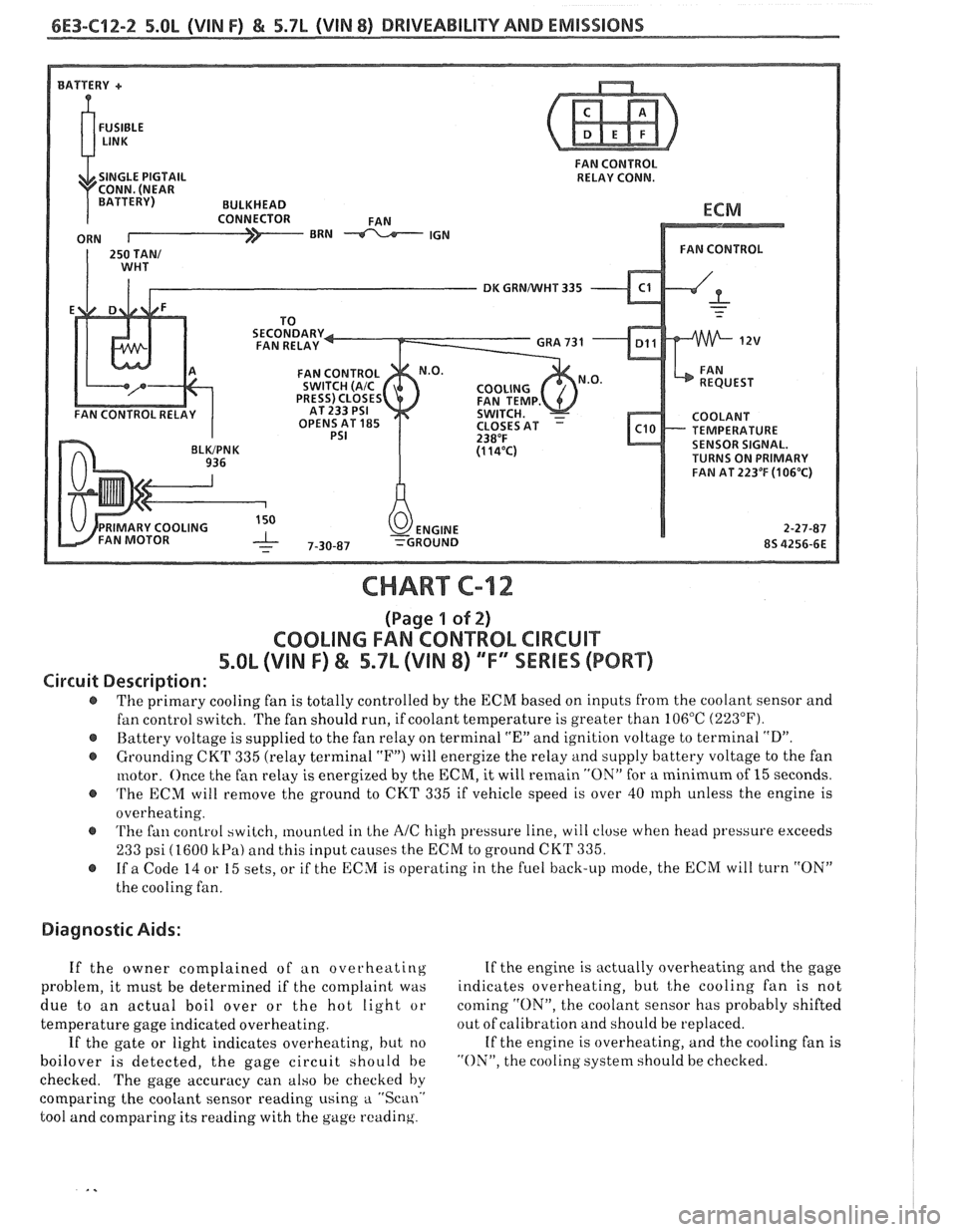
Circuit Description:
The primary cooling fan is totally controlled by the ECM based on inputs from the coolant sensor and
fan control switch. The fan should run, if coolant temperature is greater than 106°C
(223°F).
@ Battery voltage is supplied to the fan relay on terminal "En and ignition voltage to terminal "D".
@ Grounding CKT 335 (relay terminal "F") will energize the relay and supply battery voltage to the fan
motor. Once the fan relay is energized by the
ECM, it will remain "ON" for a minimum of 15 seconds.
@ 'I'he ECM will remove the ground to CKT 335 if vehicle speed is over 40 rnph unless the engine is
overheating.
@ 'I'he fan control switch, mounted in Lhe AIC high pressure line, will close when head pressure exceeds
233 psi (1600 kPa) and this input causes the ECM to ground CKT 335.
@ If a Code 14 or 15 sets, or if the ECM is operating in the fuel back-up mode, the ECM will turn "ON"
the cooling fan.
Diagnostic Aids:
If the owner complained of an overheating If
the engine is actually overheating and the gage
problem, it must be determined if the complaint was indicates
overheating, but
t,he cooling fan is not
due to an actual boil over or the hot light or coming
"ON", the
coolant sensor has probably shifted
temperature gage indicated overheating. out
of calibration and should be replaced.
If the gate or light indicates overheating, but no If
the engine is overheating, and the cooling fan is
boilover is detected, the gage circuit should be "ON", the cooling system should be checked.
checked. The gage accuracy can also be checked by
comparing the coolant sensor reading using
a "Scan.'
tool and comparing its reading with the gage reading.
Page 953 of 1825
6E3-C12-4 5.8L (VIN F) & 5.7L (VIN 8) DRIVEABILITY AND EMISSIONS
FAN CONTROL
SINGLE PIGTAIL RELAY CONN.
DK GRNNVHT 335
OPENS AT
185 TEMPERATURE SENSOR SIGNAL.
TURNS ON PRIMARY
FAN AT 223°F
(106°C)
CHART C-12
(Page 2 of 2)
COOLING FAN CONTROL CIRCUIT
5.OL (VIN F) & 5.7L (VIN 8) ""FYSERlES (PORT)
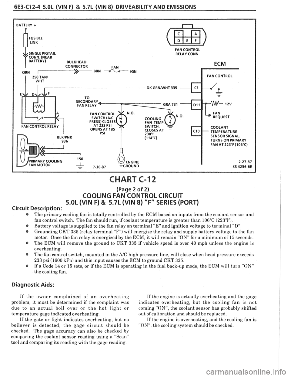
Circuit Description:
@ The primary cooling fan is totally controlled by the ECM based on inputs from the coolant sensor and
fan control switch. The fan should run, if coolant temperature is greater than 106°C
(223°F).
@ Battery voltage is supplied to the fan relay on terminal "En and ignition voltage to terminal "I)"
@ Grounding CKT 335 (relay terminal "F") will energize the relay and supply battery voltage to the fan
motor. Once the fan relay is energized by the ECM, it will remain "ON" for a mini~nuln of 15 seconds
@ The ECM will remove the ground to CKT 335 if vehicle speed is over 40 mph unless the engine is
overheating.
@ The fan control switch, mounted in the A/C high pressure line, will close when head pressure exceeds
233 psi (1600 kPa) and this input causes the ECM to ground CKT 335.
@ If a Code 14 or 15 sets, or if the ECM is operating in the fuel back-up mode, the ECM will turn "OX"
the cooling fan.
Diagnostic Aids:
If the owner complained of an overheating If the engine is actually overheating and the gage
problem, it must be determined if the complaint was indicates overheating, but the cooling fan is not
due to an actual boil over or the hot light or coming
"ON", the coolant sensor has probably shifted
temperature gage indicated overheating. out
of calibration and should be replaced.
If the gate or light indicates overheating, but no If the engine is overheating, and the cooling fan is
boilover is detected, the gage circuit should be "ON". the cooling system should be checked.
checked. The gage accuracy can also be checked
by
comparing the coolant sensor reading using a "Scan"
tool and comparing its reading with the gage reading.