1988 PONTIAC FIERO oil temperature
[x] Cancel search: oil temperaturePage 1564 of 1825
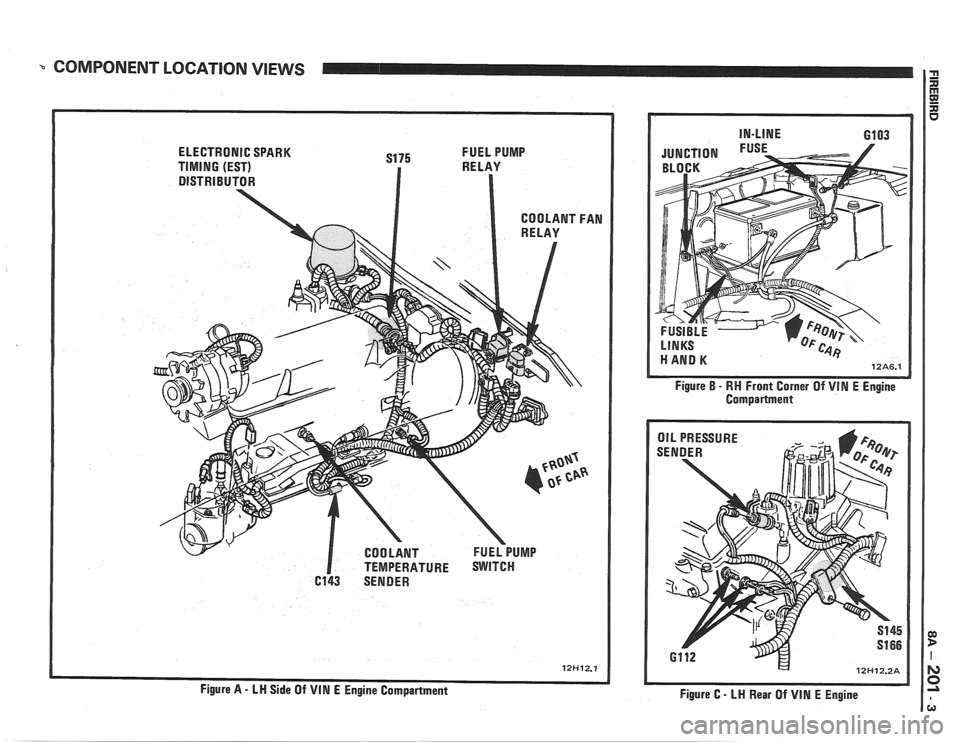
COMPONENT LOCATION VIEWS
ELECTRONIC SPARK
S175 FUEL
PUMP
TIMING (EST) RELAY
DISTRIBUTOR
I TEMPERATURE SWITCH
6143 SENDER Figure
B - RH
Front Corner Of VIM E Engine
Compartment
/ OIL PRESSURE
Figure C
- LH Rear Of VIN E Engine
Page 1565 of 1825
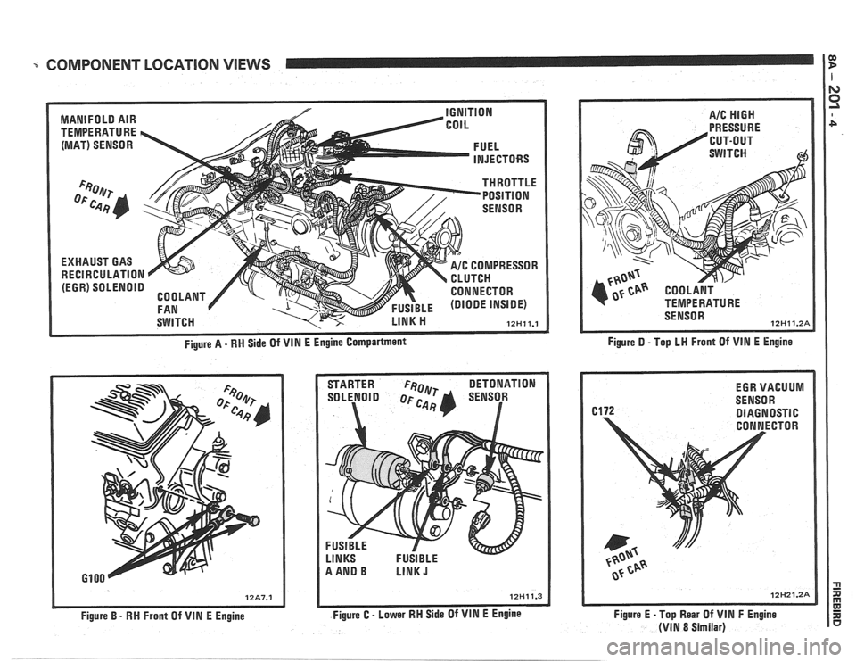
COMPONENT LOCATION VIEWS I?
MANIFOLD AIR
TEMPERATURE
h
(MAT) SENSOR
EXHAUST GAS
RECIRCULATION
(EGR) SOLENOID
IGNITION
COIL
THROTTLE POSITION
-- -
SENSOR
FUEL
INJECTORS
SWITCH COMPRESSOR
TCN
CONNECTOR
FUSIBLE (DIODE INSIDE)
LINK ti 12Hll.l
Figure A - RN Side Of VIN E Engine Compartment
STARTER
FeOlyr DETONATION
SOLENOID SENSOR
a
Figure B - RH Front Of VlN E Engine Figure
C - Lower RH Side Of VIN E Engine Figure
D - Top LN Front
Of VIN E Engine
Figure E -Top Rear Of
VIN F Engine
(VIN 8 Similar)
Page 1609 of 1825
Adjust 2 . Filler panel 3 . Electrical connector
1 . Increase Current - Turn adjusting screw 4 . ~~l~/~~~~~
clockwise 5 . Horn
2 . Decrease Current . Turn adjusting screw
counterclockwise
Install or Connect
3 . Current adjustments should be made 1/4 turn
(90") at a time
Horn Assembly
Remove or Disconnect
1 . Six screws from filler panel behind front fascia on
driver's side 1
. Horn
2 . Bolt/screw
3 . Electrical connector
4
. Filler panel
5 . Six screws
Horn Relay
The horn relay is in the convenience center.
behind the instrument panel to the right of the steering
column
. To remove the relay. pull it straight out .
REPLACEMENT LIGHT BULBS
For exterior light replacement procedures. see the rest of this
section
. For interior light replacement procedures. see Section $A
and Section 8C .
EXTERIOR LIGHTS Trade No . ...................................................................................................................... Back-up Lights 1 156
Center
High-Mounted Stoplight ............................................................................................. 577
Front Barking/Turn Signal Eights ..................................................................................... 2057
Fog Lights
............................................................................................................................... H-3
Headlights ....................................................................................................................... H6054 ................................................................................................................ License Plate Lights 194
.................................................................................... Rear Tail/Stop/Turn Signal Lights 2057
Sidemarker Lights (Front and Rear) ...................................................................................... 194 ..................................................................................................................... Underhood Light 211
BNTERBOR LIGHTS Trade No .
......................................................................................... Air Conditioner/Heater Controls 194 .................................................................................................................. Ashtray & Lighter 194 .............................................................................................................. Cargo Compartment 561
................................................................................................ Cluster & Speedometer (Tach) 194 ..................................................................................................................... Console Ashtray 194 ............................................................................................................. Console Compartment 194
Courtesy Lights
..................................................................................................................... 194 ......................................................................................................................... Dome Light 561
Gear Selector Indicator
............................................................................................................ 74 .......................................................................................... Headlight High-Beam Indicator 194
Indicator Lights
..................................................................................................... Brake System Warning 194
With Gages
........................................................................................................................ 74
............................................................... Charging System Warning (except Rally Gages) 194 .................................................................................................................... Choke Warning
194
With Gages
........................................................................................................................ 74
...................................................................... Oil Pressure Warning (except Rally Gages) 194 ............................................................................................................ Seat Belt
Reminder 194
With Gages
.................................... ... ................................................................................. 74 ............................................................................................. Service Engine Soon Warning 194
With Gages
..................................................................................................................... 74 ............................................................ Temperature Gage Warning (except Rally Gages) 194
........................................................................................................................ Reading
Light 906 ............................................................................................................ Turn Signal Indicators 194
Page 1612 of 1825
INSTRUMENT PANEL, GAGES & CONSOLE 8C-'I
SECTION 8C
NSTRUMENT PANEL, GAGES & CONSOLE
CONTENTS
General Description ................................... 8C-1
Instrument Panel and Gages ........................ 8C-1
Printed Circuit .......................................... 8C-1
Instruments ................................................... 8C- 1
Speed Sensors
............................ .. ............. 8C- 1
Pinion Gear
............................................. 8C-2
Photo Speed Sensor ................................ 8C-2
PM Generator ................... .. ...... ............... 8C-2
Speedometer ................................................ 8C-2
Mechanical ....................... .. .................... 8C-2
Quartz ........................ .. .......................... 8C-2
Digital .................... .. ...... ................. 8C-2
Fuel Gage .................................................... 8C-2
Temperature Warning Light ...................... 8C-3
Generator Warning Light ............................ 8C-3
Engine Oil Pressure Light ............................ 8C-3
"Service Engine Soon" Light ....................... 8C-3
Upshift Indicator Light .............................. 8C-3
Diagnosis .................... .. ........................... 8C-3
General Information .................................. 8C-3
Instrument Panel & Gages ...................... ..... 8C-3
On-Car Service ......................... .. ........... 8C-4
Instrument Panel Pad ................................... 8C-4
Instrument Panel Cluster ........................... 8C-4
Instrument Panel Carrier ............................. 8C-4
Headlight Switch .......................................... 8C-4
Console Mounted Switches and
Accessories
............................................... 8C-4
Console ......................................................... 8C-4
Speedometer .................................................. 8C-5
Illustra3ions ................................................. 8C-5
IP Pad ........................................................... 8C-5
IP Carrier ................................................... 8C-6
Instrument Cluster ....................................... 8C-6
Lower IP Covers ......................................... 8C-7
IP Trimplates ............................................... 8C-7
IP Hush Panels; with A/C .......................... 8C-8
..................... IP Lower Trim Pad (Console) 8C-8
Map Holder or Map Pocket ........................ 8C-8
IP Hush Panels; without A/C ..................... 8C-9
Radio Mounting ........................................... 8C-9
Subwoofer & Hatch Release
Switches/Covers ........................................ 8C- 10
Foglamp Switch/Cover ................................ 8C- 10
Oil Pressure and Temperature
Switches
..................................................... 8C-11
Heater/Ventilation/Defroster
Ductwork .................................................. 8C- 12
A/C and Defroster Ductwork ..................... 8C-13
Ram Vent System Ductwork ....................... 8C-14
Console Mounted Switches
&
Accessories ................................................. 8C- 14
Dash Insulators
............................................ 8C- 15
Heater Floor Outlet
..................................... 8C-15
................ Headlamp/Parking Lamp Switch 8C- 15
............. Dash Mounted Accessory Switches 8C- 15
GENERAL DESCRIPTION
INSTRUMENT PANEL AND GAGES
INSTRUMENTS
Instruments consist of fuel gage, temperature
The instrument panel on most cars is a sing,e unit indicator light, generator light, oil pressure indicator
design and all parts attach to the main instrument light, and speedometer. See Section 9F for optional
panel with clips and screws. To service the instrument Gages and tachometer. Service on instruments
panel and components see on-car service information, can be obtained through authorized repair stations.
However, knowledge of instrument circuit checks will
PRINTED CIRCUIT
All models are equipped with printed circuits
which supply current to most instrument panel lights
and instruments. These circuits are made of copper foil
which is die cut and bonded to a polyester base film
(usually mylar). The printed circuit electrical power is
supplied by a connector containing several wires, as
shown in the instrument panel wiring harness
installation instructions. The connector also helps
retain the printed circuit to the speedo cluster. The rest
of the circuit is retained by additional connectors (if
used) and snap-in
bulbs/sockets. For individual
printed circuit diagrams, see Section
8A-80/8 1/82/83,
'Instrument Panel'. help
in determining if operating difficulties lie in the
instrument itself or its related circuit.
Instruments have been designed for easy removal
by elimination of separate wiring. With the wiring
provisions integrated with the instrument panel wiring,
the instruments can be removed after removing the
trim and lens.
SPEED SENSORS
There are three speed sensors currently in use:
1. PINION GEAR; used in mechanical systems
2. PHOTO SPEED SENSORS; used in mechanical
systems
3. PM GENERATOR; used in electronic systems
Page 1614 of 1825
INSTRUMENT PANEL. GAGES & CONSOLE 8C-3
tank only when ignition switch is turned to "ON" or
"ACCESSORY" positions.
When ignition is turned to "OFF" or "START"
positions, the pointer may come to rest at any position.
The letters
"E" and "F" on the fuel gage are used to
point out direction of indicator travel only.
TEMPERATURE WARNING LIGHT
The engine temperature warning light is
controlled by a thermal switch which senses engine
coolant temperatures.
When the ignition switch is turned to "START"
position, a test circuit is closed and the light will come
on to indicate whether the light is functioning properly.
It is important to note that with low boiling-point
coolants (such as plain water) the temperature light
may not come on even though the coolant is boiling.
GENERATOR WARNING LIGHT
The generator warning light, located in the
instrument cluster, should come on when the ignition
switch is turned
"ON" and engine is not running. If
not, either the bulb is burned out or wiring to generator
has an open circuit.
When the generator voltage output becomes
greater than the battery voltage, the
"GEN" light
should go out. This does not, however, indicate
whether the battery is being charged or if the voltage
regulator is functioning properly.
Checks of the charging system are covered in
Section 6D, 'Engine Electrical'.
ENGINE OIL PRESSURE LIGHT
The engine oil pressure warning light is mounted
in the instrument cluster and controlled by a pressure
operated switch located on the engine block. When the ignition switch is
in the
"run" or "start9' position, the
oil pressure light should come on. If not, the bulb is
burned out, there is an open circuit between the bulb
and the oil pressure switch, or there is an open circuit
between the oil pressure switch and the choke heater.
After the engine is running, the oil pressure light
should go out when the oil pressure reaches the correct
specification. If not an oil pressure problem, a faulty oil
pressure switch or an open circuit from the choke
heater fuse to the oil pressure switch is indicated.
"SERVICE ENGINE SOON" LIGHT
All cars have a "SERVICE ENGINE SOON"
light mounted in the instrument cluster. The
"SERVICE ENGINE SOON9' light should come on
during engine starting. The light may stay on
a short
time after the engine starts.
If the light comes on while
driving, service to the emission control system may be
required. See Section
6E and Section 8A-80,
'Instrument Cluster', for complete diagnosis and
wiring diagrams of the
""P;RVICE ENGINE SOON"
light circuit.
UPSHIFT INDICATOR LIGHT
If your vehicle has a manual transmission, there
may be an
''Upshift" light on the instrument panel.
This light is illuminated to indicate optimum shift
points throughout the range from optimum fuel
economy to optimum performance. When this light is
on, shift your transmission to the next higher gear
range if conditions permit. For fuel economy,
accelerate slowly and shift when the light goes on. For
performance, accelerate as desired and shift when the
light goes on.
Safe operation of the vehicle may require shifting
differently than indicated by the "Upshift" light to
adapt to weather, road or traffic conditions.
Downshifting one or more gears may be required
to keep the engine running smoothly or to maintain
satisfactory performance.
DIAGNOSIS
Diagnostic information for all instrument panel
electrical systems is found in Section
8A-80,
'Instrument Panel'.
CAUTION: When removing or
installing any electrical units,
disconnect the negative battery cable
to prevent possible short circuits
which could lead to personal injury
and/or property damage. When
replacing a speedometer or
odometer assembly, the law requires the
odometer reading of the replacement unit to
be set to register the same mileage as the
prior odometer.
if the same mileage cannot be
set, the
law requires that the replacement
odometer be set to zero and a label be
installed on the driver's door frame to show
the previous odometer reading and the date
of replacement.
GENERAL BNFORMATlOM
INSTRUMENT PANEL AND GAGES
The instrument panel is a single unit design and
and screws. To service the instrument panel and
all parts attach to the main instrument panel with clips components see Figs. 601 through 610.
Page 1622 of 1825
INSTRUMENT PANEL. GAGES & CONSOLE 8C-11
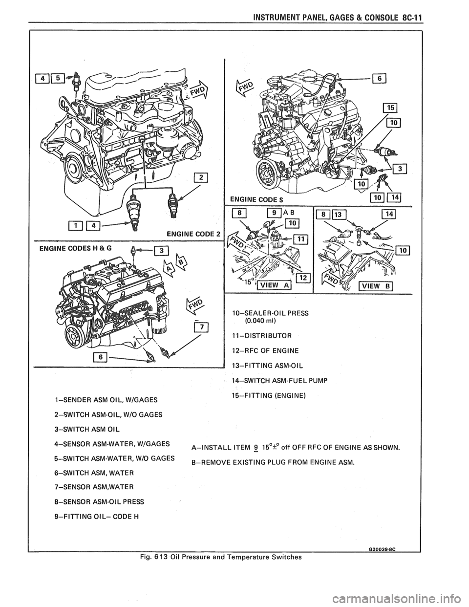
ENGINE CODE 2
ENGINE CODES H & G
10-SEALER-OI L PRESS
(0.040 ml)
12-RFC OF ENGINE
13-FITTING ASM-OIL
14-SWITCH ASM-FUEL PUMP
I
1-SENDER ASM OIL, WIGAGES 15-FITTING (ENGINE)
I
2-SWITCH ASM-OI L, WIO GAGES
3-SWITCH ASM OIL
4-SENS0R ASM-WATER' A-INSTALL ITEM g 15'9 off OFF RFC OF ENGINE AS SHOWN.
ASM-WATER' W1O GAGES B-REMOVE EXISTING PLUG FROM ENGINE ASM.
6-SWITCH ASM, WATER
8-SENSOR ASM-OI L
PR ESS
I 9-FITTING OIL- CODE H
Fig.
6 13 Oil Pressure and Temperature Switches
Page 1674 of 1825
MISCELLANEOUS ACCESSORIES 96-4
SCELLANEOUS ACCESSOR
General Description ................................. 9G-1
Rally Gages .................................................. 9G- 1
Tachometer ................................................. 9G- 1
Trip Odometer
............................................. 9G- 1
Electric Rear Window Defogger ................. 9G-2
Power Remote Control Rearview
Mirror ........................................................ 9G-2
Diagnosis .................................................... 9G-2
Rally Gages ............................................... 9G-2
Tachometer .................................... .... .... 9G-2
Electric Rear Window Defogger ................. 9G-2
Power Remote Control Rearview
Mirror ........................................................ 96-2
Dash and Console Mounted
Accessory Switches
................................. 9G-4
General Description .................................. 9G-4
Electronic Glare Control Mirror ................. 9G-4
On-Car Service ............................................. 9G-4
Rally Gages, Tach ....................................... 96-4.
Rear Window Defogger ............................ 96-4.
Power Remote Control Mirror .................... 9G-4
GENERAL BESCRIP"T0N
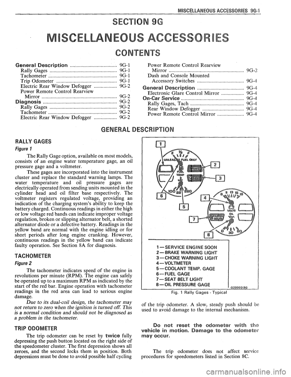
RALLY GAGES
Figure I
The Rally Gage option, available on most models,
consists of an engine water temperature gage, an oil
pressure gage and a voltmeter.
These gages are incorporated into the instrument
cluster and replace the standard warning lamps. The
water temperature and oil pressure gages are
electrically operated from sending units mounted in the
cylinder head and oil filter base respectively. The
voltmeter registers regulated voltage, providing an
indication of the charging system's ability to keep the
battery charged. Continuous readings in either the high
or low voltage red bands can indicate improper voltage
regulation, broken or slipping alternator belt,
a shorted
alternator diode
or a defective battery. Readings in the
yellow band are normal with the engine idling or for
short periods after long engine cranking. However,
continuous readings in the yellow band can indicate
faulty operation. See Section
8A for diagnosis.
TACHOMETER
Figure 2
The tachometer indicates speed of the engine in
revolutions per minute (RPM). The engine can safely
be operated up to a maximum RPM as indicated by the
start of the red bar. Engine operation with tachometer
readings in the red area can lead to serious engine
damage.
Due to its dual-coil design, the tachometer may
not return to zero when the ignition
is turned oft: This
is
a normal condition and should not be diagnosed as
a problem in the tachometer.
TRIP ODOMETER
The trip odometer can be reset by twice fully
depressing the push button located on the right side of
the speedometer cluster. The first depression shows all
zeroes, and the second locks them in position. Both
depressions must be done to avoid possible half cycling
I -SERVICE ENGINE SOON
2-BRAKE WARNING LIGHT
3-CHOKE WARNING LIGHT
4-VOLTMETER
5-COOUNT TEMP. GAGE
6-FUEL GAGE
7-SEAT BELT LIGHT
8-OIL PRESSURE GAGE G20003 9G
Fig. 1 Rally Gages - Typical
of the trip odometer. A slow, steady push should be
used to avoid damage to the internal mechanism.
Do not reset the odometer with the
vehicle in motion. Damage to the odometer
may occur.
The trip odometer does not affect service
procedures for speedometers listed in Section
8C.
Page 1684 of 1825
GENERAL INFORMAVlOM - F STYLE "1-3
Compartment lid hinges - part no. 1052196,
Lubriplate Auto Lube A; part no.
1052349,
Lubriplate Spray Lube A, part no. 8915,
3M
Lithium Spray Lube or equivalent.
Black lock cylinders
- light oil.
e All other lock cylinders - a general purpose
silicone lubricant, part no. 1052277 or equivalent.
e Seat mechanism and door hardware are covered
in the specific body area sections in this manual.
All weatherstrips should be periodically
lubricated with a silicone paste lubricant, part no.
1052363, or equivalent. A thin film of lubricant
should be applied using a clean cloth.
ADHESIVE BODY SlBE MOLDING
The body side moldings are attached to the body
panels with adhesive tape. To insure a good molding
replacement (new or old moldings), the panel surface
should be warm (21°C to 32°C or 70°F to
90°F), clean
and free of any wax or oily film. Two methods are listed
to attach loose molding ends and completely removed
m~ldings.
Molding End Loose
1. Wash affected area with soap and water and wipe
dry. Wipe panel and adhesive side of molding
with a clean rag using oil-free naphtha or alcohol.
If molding has pulled loose from adhesive
backing (tape remains on body panel), do not
remove tape from body. Clean back of molding
and tape on body with oil-free naphtha or alcohol
and proceed with step 3.
2. If needed, apply a length of masking tape as a
molding guide.
A straightedge may also be used
in most cases.
3. Apply adhesive to back of molding and press in
place. If Loctite
414 adhesive (part no. 1052283)
or equivalent is used, apply constant pressure to
molding for 30 seconds or until a firm bond has
been made.
Molding Completely Removed
1.
Wash affected panel area with soap and water
and wipe dry. Remove all traces of adhesive from
body panel and back of molding using oil-free
naphtha or alcohol.
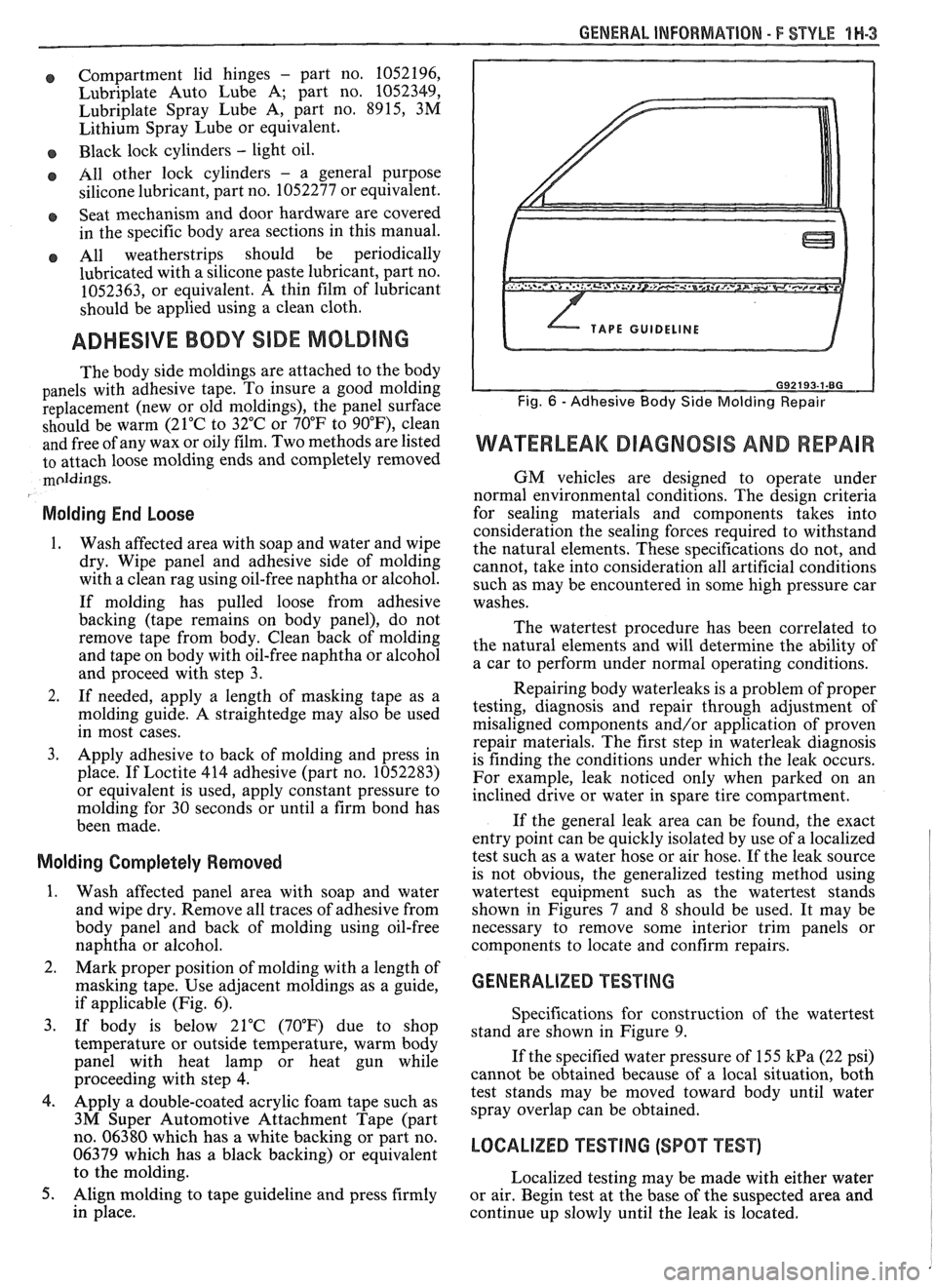
2. Mark proper position of molding with a length of
masking tape. Use adjacent moldings as a guide,
if applicable (Fig. 6).
3. If body is below 21°C (70°F) due to shop
temperature or outside temperature, warm body
panel with heat lamp or heat gun while
proceeding with step
4.
4. Apply a double-coated acrylic foam tape such as
3M Super Automotive Attachment Tape (part
no. 06380 which has a white backing or part no.
06379 which has a black backing) or equivalent
to the molding.
5. Align molding to tape guideline and press firmly
in place.
WATERLEAK DIAGNOSIS AND REPAIR
GM vehicles are designed to operate under
normal environmental conditions. The design criteria
for sealing materials and components takes into
consideration the sealing forces required to withstand
the natural elements. These specifications do not, and
cannot, take into consideration all artificial conditions
such as may be encountered in some high pressure car
washes.
The watertest procedure has been correlated to
the natural elements and will determine the ability of
a car to perform under normal operating conditions.
Repairing body waterleaks is a problem of proper
testing, diagnosis and repair through adjustment of
misaligned components and/or application of proven
repair materials. The first step in waterleak diagnosis
is finding the conditions under which the leak occurs.
For example, leak noticed only when parked on an
inclined drive or water in spare tire compartment.
If the general leak area can be found, the exact
entry point can be quickly isolated by use of a localized
test such as a water hose or air hose. If the leak source
is not obvious, the generalized testing method using
watertest equipment such as the watertest stands
shown in Figures
7 and 8 should be used. It may be
necessary to remove some interior trim panels or
components to locate and confirm repairs.
GENERALIZED TESTING
Specifications for construction of the watertest
stand are shown in Figure 9.
If the specified water pressure of 155
kPa (22 psi)
cannot be obtained because of a local situation, both
test stands may be moved toward body until water
spray overlap can be obtained.
LOCALIZED TEST lNG (SPOT TEST)
Localized testing may be made with either water
or air. Begin test at the base of the suspected area and
continue up slowly until the leak is located.