1988 PONTIAC FIERO check engine light
[x] Cancel search: check engine lightPage 399 of 1825
6A3-20 V-8 ENGINE
PLASTIC GAGE
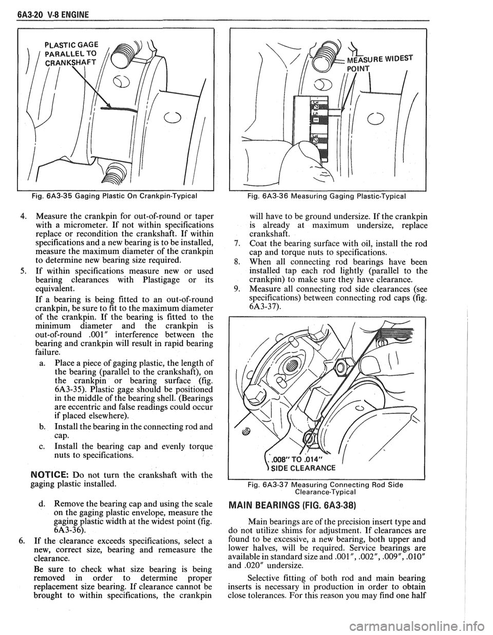
Fig. 6A3-35 Gaging Plastic On Crankpin-Typical
4. Measure the crankpin for out-of-round or taper
with a micrometer. If not within specifications
replace or recondition the crankshaft. If within
specifications and a new bearing is to be installed,
measure the maximum diameter of the
crankpin
to determine new bearing size required.
5. If within specifications measure new or used
bearing clearances with Plastigage or its
equivalent.
If a bearing is being fitted to an out-of-round
crankpin, be sure to fit to the maximum diameter
of the crankpin. If the bearing is fitted to the
minimum diameter and the
crankpin is
out-of-round .OO 1
" interference between the
bearing and
crankpin will result in rapid bearing
failure.
a. Place a piece of gaging plastic, the length of
the bearing (parallel to the crankshaft), on
the
crankpin or bearing surface (fig.
6A3-35). Plastic gage should be positioned
in the middle of the bearing shell. (Bearings
are eccentric and false readings could occur
if placed elsewhere).
b. Install the bearing in the connecting rod and
cap.
c. Install the bearing cap and evenly torque
nuts to specifications.
NOTICE: Do not turn the crankshaft with the
gaging plastic installed.
d. Remove the bearing cap and using the scale
on the gaging plastic envelope, measure the
gaging plastic width at the widest point (fig.
6A3-36).
6. If the clearance exceeds specifications, select a
new, correct size, bearing and remeasure the
clearance.
Be sure to check what size bearing is being
removed in order to determine proper
replacement size bearing. If clearance cannot be
brought to within specifications, the
crankpin
Fig. 6A3-36 Measuring Gaging Plastic-Typical
will have to be ground undersize. If the crankpin
is already at maximum undersize, replace
crankshaft.
7. Coat the bearing surface with oil, install the rod
cap and torque nuts to specifications.
8. When all connecting rod bearings have been
installed tap each rod lightly (parallel to the
crankpin) to make sure they have clearance.
9. Measure all connecting rod side clearances (see
specifications) between connecting rod caps (fig.
6A3-37).
..WS1'TQ.014" 1
s
/
SIDE CLEARANCE
Fig.
6A3-37 Measuring Connecting Rod Side
Clearance-Typical
MAIN BEARINGS (FIG. 8A3-38)
Main bearings are of the precision insert type and
do not utilize shims for adjustment. If clearances are
found to be excessive, a new bearing, both upper and
lower halves, will be required. Service bearings are
available in standard size and
,001 ", .002", .009", .01OV
and .020" undersize.
Selective fitting of both rod and main bearing
inserts is necessary in production in order to obtain
close tolerances. For this reason you may find one half
Page 403 of 1825
6A3-24 V.8 ENGINE
3. Use a ridge reamer to remove any ridge and/or
deposits from the upper end of the cylinder bore.
4. Turn crankshaft until piston is at top of stroke
and remove cloth and cuttings.
5. Remove connecting rod cap and install Tool
J-5239 (3/8") on studs. Push connecting rod and
piston assembly out of top of cylinder block. It
will be necessary to turn the crankshaft slightly
to disconnectt some of the connecting rod and
piston assemblies and push them out of the
cylinder.
Disassembly
1. Remove connecting rod bearings from
connecting rods and caps. If bearings are being
reused, place them in a rack so they may be
reinstalled in their original rod and cap.
2. Remove piston rings by expanding and sliding
them off the pistons.
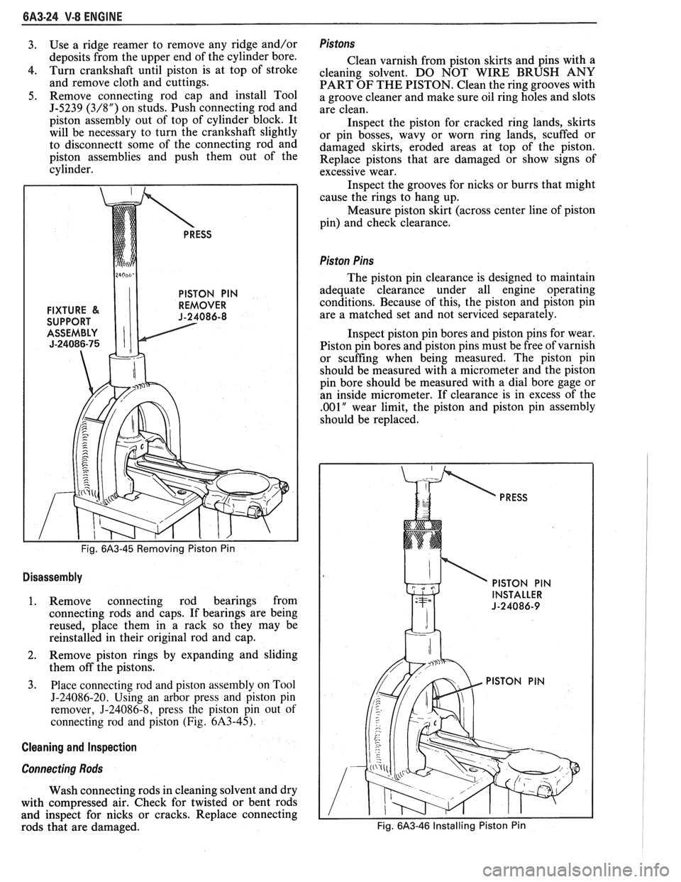
3. Piace connecting rod and piston assembly on Tool
J-24086-20. Using an arbor press and piston pin
remover,
5-24086-8, press the piston pin out of
connecting rod and piston (Fig. 6A3-45).
Cleaning and Inspection
Connecting Rods
Wash connecting rods in cleaning solvent and dry
with compressed air. Check for twisted or bent rods
and inspect for nicks or cracks. Replace connecting
rods that are damaged.
Pis tons
Clean varnish from piston skirts and pins with a
cleaning solvent. DO NOT WIRE BRUSH ANY
PART OF THE PISTON. Clean the ring grooves with
a groove cleaner and make sure oil ring holes and slots
are clean.
Inspect the piston for cracked ring lands, skirts
or pin bosses, wavy or worn ring lands, scuffed or
damaged skirts, eroded areas at top of the piston.
Replace pistons that are damaged or show signs of
excessive wear.
Inspect the grooves for nicks or burrs that might
cause the rings to hang up.
Measure piston skirt (across center line of piston
pin) and check clearance.
Pis ton Pins
The piston pin clearance is designed to maintain
adequate clearance under all engine operating
conditions. Because of this, the piston and piston pin
are a matched set and not serviced separately.
Inspect piston pin bores and piston pins for wear.
Piston pin bores and piston pins must be free of varnish
or scuffing when being measured. The piston pin
should be measured with a micrometer and the piston
pin bore should be measured with a dial bore gage or
an inside micrometer. If clearance is in excess of the
,001" wear limit, the piston and piston pin assembly
should be replaced.
PRESS
PISTON PIN
INSTALLER
J-24086-9
Fig. 6A3-46 Installing Piston Pin
Page 404 of 1825
V-8 ENGINE 6A3-25
Assembly
1. Lubricate piston pin holes in piston and
connecting rod to facilitate installation of pin.
2. Place connecting rod in piston and hold in place
with piston pin guide and piston pin. Place
assembly on fixture and support assembly.
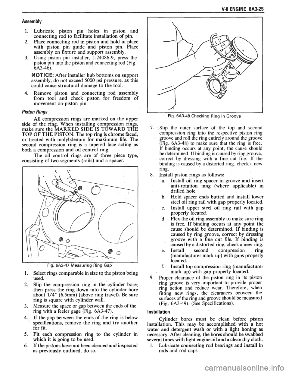
3. Using piston pin installer, 5-24086-9, press the
piston pin into the piston and connecting rod (Fig.
6A3-46).
NOTICE: After installer hub bottoms on support
assembly, do not exceed
5000 psi pressure, as this
could cause structural damage to the tool.
4. Remove piston
and connecting rod assembly
from tool and check piston for freedom of
movement on piston pin.
Piston Rings
All compression rings are marked on the upper
side of the ring. When installing compression rings,
make sure the MARKED SIDE IS TOWARD THE
TOP
OF THE PISTON. The top ring is chrome faced,
or treated with molybdenum for maximum life. The
second compression ring is a tapered face acting as
both a compression and oil control ring.
The oil control rings are of three piece type,
consisting of two segments (rails) and a spacer.
Fig. 6A3-47 Measuring Ring Gap
1. Select rings comparable in size to the piston being
used.
2. Slip the compression ring in the cylinder bore;
then press the ring down into the cylinder bore
about
1/4" (6.5mm) (above ring travel). Be sure
ring is square with cylinder wall.
3. Measure the space or gap between the ends of the
ring with a feeler gage (Fig.
6A3-47).
4. If the gap between the ends of the ring is below
specifications, remove the ring and try another
for fit.
5. Fit each compression ring to the cylinder in
which it is going to be used.
6. If the pistons have not been cleaned and inspected
as previously outlined, do so.
Fig. 6A3-48 Checking Ring in Groove
7. Slip the outer surface of the top and second
compression ring into the respective piston ring
groove and roll the ring entirely around the groove
(Fig.
6A3-48) to make sure that the ring is free.
If binding occurs at any point, the cause should
be determined. If binding is caused by ring groove,
correct by dressing with a fine cut file. If
the
binding is caused by a distorted ring, check a new
ring.
8. Install piston rings as follows:
a. Install oil ring spacer in groove and insert
anti-rotation tang (where applicable) in
drilled hole.
b. Hold spacer ends butted and install lower
steel oil ring rail with gap properly located.
c. Install
upper steel oil ring rail with gap
properly located.
d. Flex the oil ring assembly to make sure ring
is free. If binding occurs at any point the
cause should be determined. If binding is
caused by ring groove, correct by dressing
groove with a fine cut file. If binding is
caused by a distorted ring, check a new ring.
e. Install second compression ring
(manufacturer mark up) with gaps properly
located.
f. Install top compression ring (manufacturer
mark up) with gap properly located.
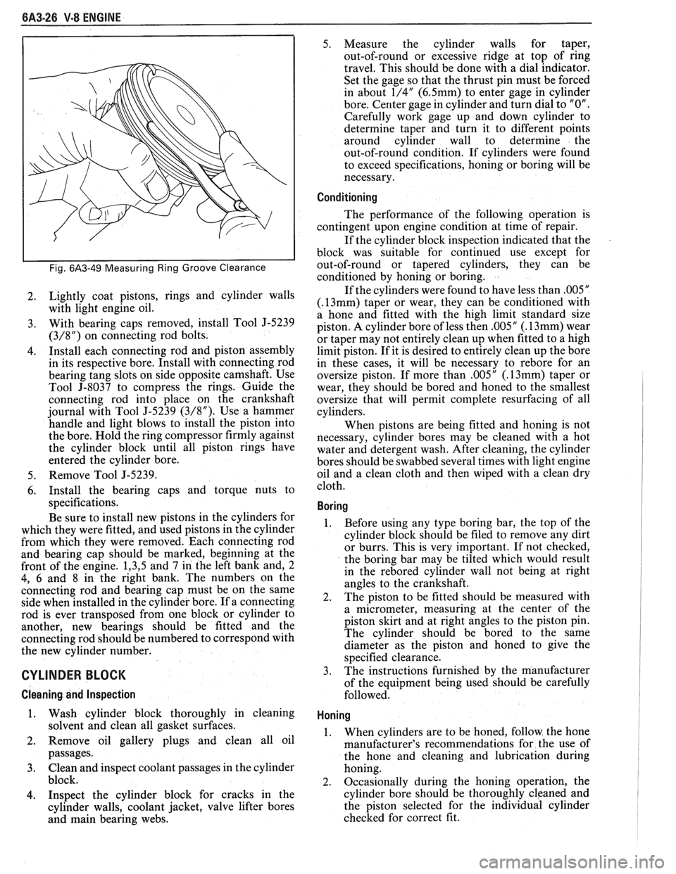
9. Proper clearance of the piston ring in its piston
ring groove is very important to provide proper
ring action and reduce wear. Therefore, when
fitting new rings, the clearances between the
surfaces of the ring and groove should be measured
(Fig.
6A3-49). (See Specifications).
Installation
Cylinder bores must be clean before piston
installation. This may be accomplished with a hot
water and detergent wash or with a light honing as
necessary. After cleaning, the bores should be swabbed
several times with light engine oil and a clean dry cloth.
1. Lubricate connecting rod bearings and install in
rods and rod caps.
Page 405 of 1825
6A3-26 V-8 ENGINE
Fig. 6A3-49 Measuring Ring Groove Clearance
2. Lightly coat pistons, rings
and cylinder walls
with light engine oil.
3. With bearing caps removed, install Tool J-5239
(3/8") on connecting rod bolts.
4. Install
each connecting rod and piston assembly
in its respective bore. Install with connecting rod
bearing tang slots on side opposite camshaft. Use
Tool
5-8037 to compress the rings. Guide the
connecting rod into place on the crankshaft
journal with Tool
5-5239 (3/8"). Use a hammer
handle and light blows to install the piston into
the bore. Hold the ring compressor firmly against
the cylinder block until all piston rings have
entered the cylinder bore.
5. Remove Tool J-5239.
6. Install the bearing caps and torque nuts to
specifications.
Be sure to install new pistons in the cylinders for
which they were fitted, and used pistons in the cylinder
from which they were removed. Each connecting rod
and bearing cap should be marked, beginning at the
front of the engine.
1,3,5 and 7 in the left bank and, 2
4, 6 and 8 in the right bank. The numbers on the
connecting rod and bearing cap must be on the same
side when installed in the cylinder bore. If a connecting
rod is ever transposed from one block or cylinder to
another, new bearings should be fitted and the
connecting rod should be numbered to correspond with
the new cylinder number.
CYLINDER BLOCK
Cleaning and Inspection
1. Wash cylinder block thoroughly in cleaning
solvent and clean all gasket surfaces.
2. Remove oil gallery plugs and clean all oil
passages.
3. Clean and inspect coolant passages in the cylinder
block.
4. Inspect the cylinder block for cracks in the
cylinder walls, coolant jacket, valve lifter bores
and main bearing webs. 5.
Measure the cylinder walls for taper,
out-of-round or excessive ridge at top of ring
travel. This should be done with a dial indicator.
Set the gage so that the thrust pin must be forced
in about
1/4" (6.5mm) to enter gage in cylinder
bore. Center gage in cylinder and turn dial to
"0".
Carefully work gage up and down cylinder to
determine taper and turn it to different points
around cylinder wall to determine the
out-of-round condition. If cylinders were found
to exceed specifications, honing or boring will be
necessary.
Conditioning
The performance of the following operation is
contingent upon engine condition at time of repair.
If the cylinder block inspection indicated that the
block was suitable for continued use except for
out-of-round or tapered cylinders, they can be
conditioned by honing or boring.
If the cylinders were found to have less than
.005"
(.13mm) taper or wear, they can be conditioned with
a hone and fitted with the high limit standard size
piston. A cylinder bore of less then
.005" (. 13mm) wear
or taper may not entirely clean up when fitted to a high
limit piston. If it is desired to entirely clean up the bore
in these cases, it will be necessary to
rebore for an
oversize piston. If more than
.005" (. 13mm) taper or
wear, they should be bored and honed to the smallest
oversize that will permit complete resurfacing of all
cylinders.
When pistons are being fitted and honing is not
necessary, cylinder bores may be cleaned with a hot
water and detergent wash. After cleaning, the cylinder
bores should be swabbed several times with light engine
oil and a clean cloth and then wiped with a clean dry
cloth.
Boring
1. Before using any type boring bar, the top of the
cylinder block should be filed to remove any dirt
or burrs. This is very important. If not checked,
the boring bar may be tilted which would result
in the
rebored cylinder wall not being at right
angles to the crankshaft.
2. The
piston to be fitted should be measured with
a micrometer, measuring at the center of the
piston skirt and at right angles to the piston pin.
The cylinder should be bored to the same
diameter as the piston and honed to give the
specified clearance.
3.
The instructions furnished by the manufacturer
of the equipment being used should be carefully
followed.
Honing
1. When cylinders are to be honed, follow the hone
manufacturer's recommendations for the use of
the hone and cleaning and lubrication during
honing.
2. Occasionally during the honing operation, the
cylinder bore should be thoroughly cleaned and
the piston selected for the individual cylinder
checked for correct fit.
Page 415 of 1825
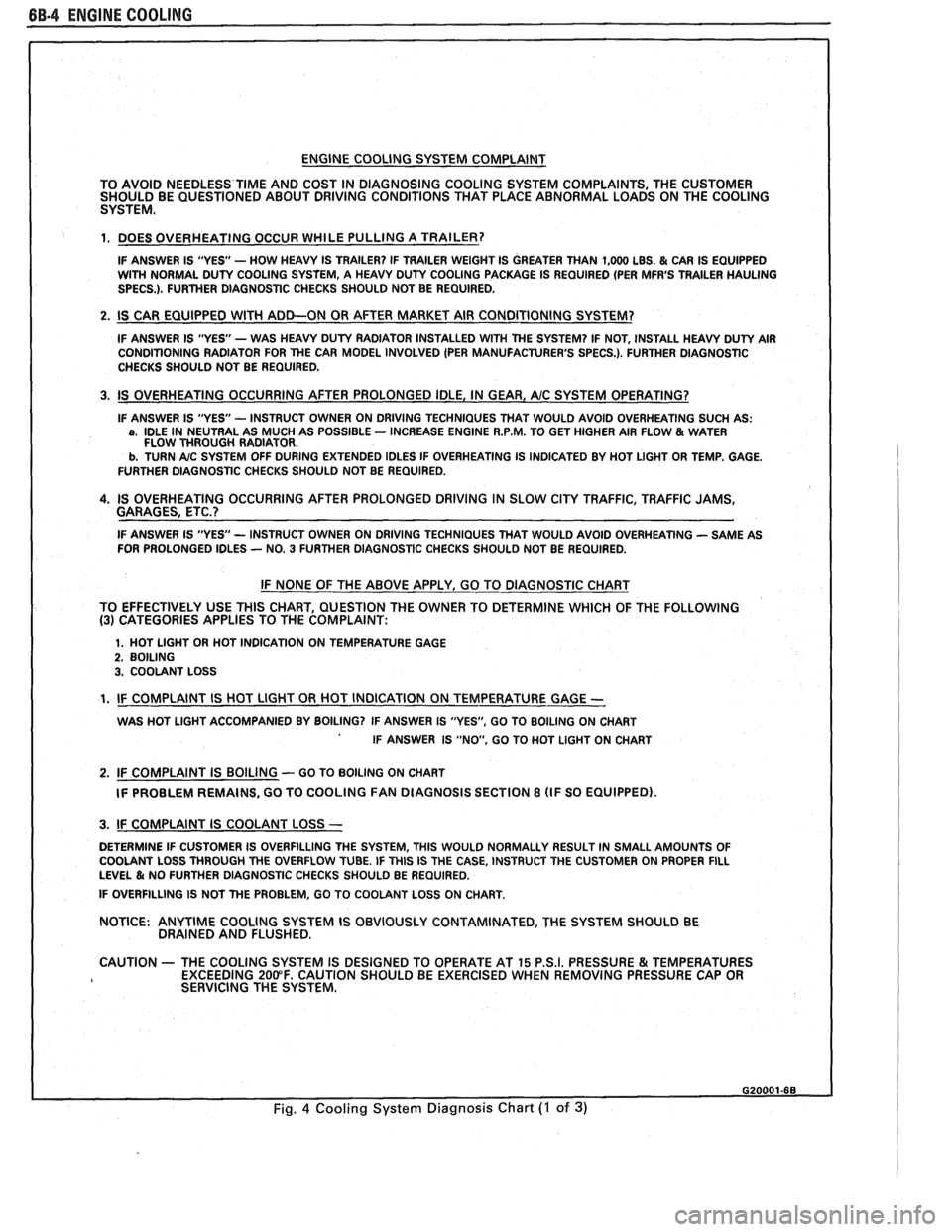
BB.4 ENGINE COOLING
ENGINE COOLING SYSTEM COMPLAINT
TO AVOID NEEDLESS
TIME AND COST IN DIAGNOSING COOLING SYSTEM COMPLAINTS, THE CUSTOMER
SHOULD BE QUESTIONED ABOUT DRIVING CONDITIONS THAT PLACE ABNORMAL LOADS ON THE COOLING
SYSTEM.
1. DOES OVERHEATING OCCUR WHILE PULLING A TRAILER?
IF ANSWER IS "YES'- HOW HEAVY IS TRAILER? IF TRAILER WEIGHT IS GREATER THAN 1,000 LBS. & CAR IS EQUIPPED
WITH NORMAL DUTY COOLING SYSTEM, A HEAVY DUTY COOLING PACKAGE IS REQUIRED (PER MFR'S TRAILER HAULING
SPECS.). FURTHER DIAGNOSTIC CHECKS SHOULD NOT BE REQUIRED.
2. IS CAR EQUIPPED WlTH ADD-ON OR AFTER MARKET AIR CONDITIONING SYSTEM?
IF ANSWER IS "YES"- WAS HEAVY DUTY RADIATOR INSTALLED WITH THE SYSTEM? IF NOT, INSTALL HEAVY DUTY AIR
CONDITIONING RADIATOR FOR THE CAR MODEL INVOLVED (PER MANUFACTURER'S SPECS.). FURTHER DlAGNOSTlC
CHECKS SHOULD NOT BE REQUIRED.
3. IS OVERHEATING OCCURRING AFTER PROLONGED IDLE, IN GEAR, AIC SYSTEM OPERATING?
IF ANSWER IS "YES - INSTRUCT OWNER ON DRIVING TECHNIQUES THAT WOULD AVOID OVERHEATING SUCH AS: a, IDLE IN NEUTRAL AS MUCH AS POSSIBLE - INCREASE ENGINE R.P.M. TO GET HIGHER AIR FLOW & WATER
FLOW THROUGH RADIATOR.
b. TURN A/C SYSTEM OFF DURING EXTENDED IDLES IF OVERHEATING IS INDICATED BY HOT LIGHT OR TEMP. GAGE.
FURTHER DIAGNOSTIC CHECKS SHOULD NOT BE REQUIRED.
4. IS OVERHEATING OCCURRING AFTER PROLONGED DRIVING IN SLOW CITY TRAFFIC, TRAFFIC JAMS,
GARAGES, ETC.?
IF ANSWER IS "YES - INSTRUCT OWNER ON DRIVING TECHNIQUES THAT WOULD AVOID OVERHEATING - SAME AS
FOR PROLONGED IDLES - NO. 3 FURTHER DIAGNOSTIC CHECKS SHOULD NOT BE REQUIRED.
IF NONE OF THE ABOVE APPLY, GO TO DIAGNOSTIC CHART
TO EFFECTIVELY USE THlS CHART, QUESTION THE OWNER TO DETERMINE WHICH OF THE FOLLOWING
(3) CATEGORIES APPLIES TO THE COMPLAINT:
1. HOT LlGHT OR HOT INDICATION ON TEMPERATURE GAGE 2. BOILING 3. COOLANT LOSS
1. IF COMPLAINT IS HOT LlGHT OR HOT INDICATION ON TEMPERATURE GAGE -
WAS HOT LlGHT ACCOMPANIED BY BOILING? IF ANSWER IS "YES", GO TO BOILING ON CHART
IF ANSWER IS "NO, GO TO HOT LlGHT ON CHART
2. IF COMPLAINT IS BOILING - GO TO BOILING ON CHART
IF PROBLEM REMAINS, GO TO COOLING
FAN DIAGNOSIS SECTION 8 (IF SO EQUIPPED).
I 3. IF COMPLAINT IS COOLANT LOSS -
DETERMINE IF CUSTOMER IS OVERFILLING THE SYSTEM, THlS WOULD NORMALLY RESULT IN SMALL AMOUNTS OF
I COOLANT LOSS THROUGH THE OVERFLOW TUBE. IF THlS IS THE CASE, INSTRUCT THE CUSTOMER ON PROPER FILL LEVEL & NO FURTHER DIAGNOSTIC CHECKS SHOULD BE REQUIRED.
I IF OVERFILLING IS NOT THE PROBLEM, GO TO COOLANT LOSS ON CHART.
NOTICE:
ANYTIME COOLING SYSTEM IS OBVIOUSLY CONTAMINATED, THE SYSTEM SHOULD BE
DRAINED AND FLUSHED.
1 CAUTION - THE COOLING SYSTEM IS DESIGNED TO OPERATE AT 15 P.S.I. PRESSURE & TEMPERATURES
EXCEEDING 200°F. CAUTION SHOULD BE EXERCISED WHEN REMOVING PRESSURE CAP OR
I SERVICING THE SYSTEM.
Fig. 4 Cooling System Diagnosis Chart (I of 3)
Page 447 of 1825
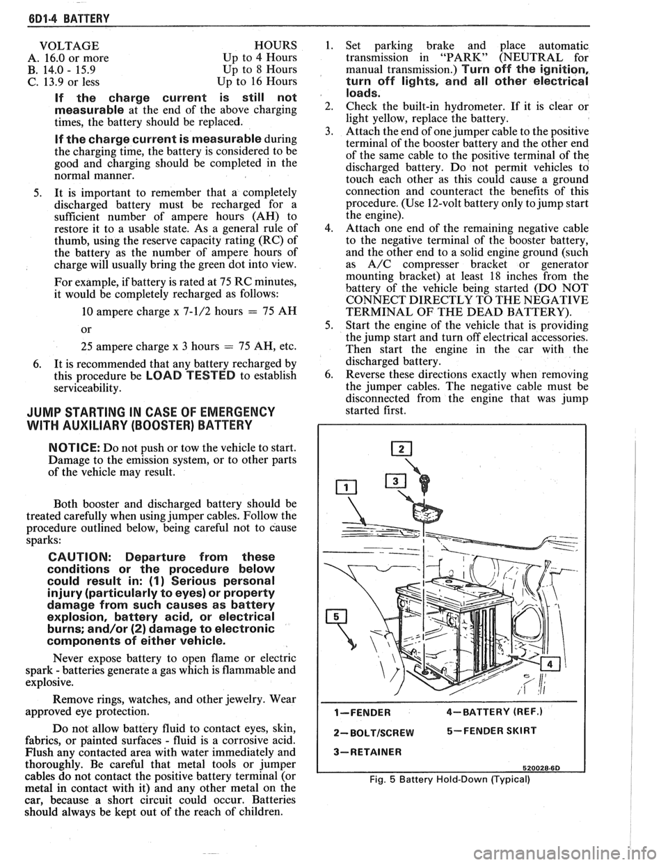
6D1-4 BATTERY
VOLTAGE
A. 16.0 or more
B. 14.0
- 15.9
C. 13.9 or less HOURS
1. Set parking brake and place automatic
Up to 4 Hours transmission in "PARK" (NEUTRAL for
Up to 8 Hours manual transmission.) Turn off the ignition,
Up to 16 Hours turn off lights, and all other electrical
If the charge current is still not
measurable
at the end of the above charging
times, the battery should be replaced.
If the charge current is measurable during
the charging time, the battery is considered to be
good and charging should be completed in the
normal manner.
5. It
is important to remember that a completely
discharged battery must be recharged for a
sufficient number of ampere hours (AH) to
restore it to a usable state. As a general rule of
thumb, using the reserve capacity rating (RC) of
the battery as the number of ampere hours of
charge will usually bring the green dot into view.
For example, if battery is rated at 75 RC minutes,
it would be completely recharged as follows:
10 ampere charge x 7-1/2 hours
= 75 AH
25 ampere charge x 3 hours = 75 AH, etc.
6. It
is recommended that any battery recharged by
this procedure be
LOAD TESTED to establish
serviceability.
JUMP STARTING IN CASE OF EMERGENCY
WITH AUXILIARY (BOOSTER) BAVEEWY
NOTICE: Do not push or tow the vehicle to start.
Damage to the emission system, or to other parts
of the vehicle may result.
Both booster and discharged battery should be
treated carefully when using jumper cables. Follow the
procedure outlined below, being careful not to cause
sparks:
CAUTION: Departure from these
conditions or the procedure below
could result in:
(1) Serious personal
injury (particularly to eyes) or property
damage from such causes as battery
explosion, battery acid, or electrical
burns; and/or
(2) damage to electronic
components of either vehicle.
Never expose battery to open flame or electric
spark
- batteries generate a gas which is flammable and
explosive.
Remove rings, watches, and other jewelry. Wear
approved eye protection.
Do not allow battery fluid to contact eyes, skin,
fabrics, or painted surfaces
- fluid is a corrosive acid.
Flush any contacted area with water immediately and
thoroughly. Be careful that metal tools or jumper
cables do not contact the positive battery terminal (or
metal in contact with it) and any other metal on the
car, because a short circuit could occur. Batteries
should always be kept out of the reach of children.
loads.
2. Check the built-in hydrometer. If it is clear or
light yellow, replace the battery.
3. Attach the end of one jumper cable to the positive
terminal of the booster battery and the other end
of the same cable to the positive terminal of the
discharged battery. Do not permit vehicles to
touch each other as this could cause a ground
connection and counteract the benefits of this
procedure. (Use 12-volt battery only to jump start
the engine).
4. Attach one end of the remaining negative cable
to the negative terminal of the booster battery,
and the other end to a solid engine ground (such
as
A/C compresser bracket or generator
mounting bracket) at least 18 inches from the
battery of the vehicle being started (DO NOT
CONNECT DIRECTLY TO THE NEGATIVE
TERMINAL OF THE DEAD BATTERY).
5. Start the engine of the vehicle that is providing
the jump start and turn off electrical accessories.
Then start the engine in the car with the
discharged battery.
6. Reverse these directions exactly when removing
the jumper cables. The negative cable must be
disconnected from the engine that was jump
started first.
I-FENDER 4-BATTERY (REF.)
2- BOLTISCREW 5-FENDER SKIRT
3-RETAINER
520028-60
Fig. 5 Battery Hold-Down (Typical)
Page 464 of 1825
CHARGING SYSTEM 6D3-1
SECTION 6D3
CHARG NG SYSTEM
CONTENTS
General Description ................................. 6D3- 1 Charging System ........................................ 6D3- 1
.......................................... Charging System - CS ............................... 6D3- 1 On-Car Service 6D3-2
................................................... Diagnosis .. 6D3- 1 Generator 6D3-3 ...................... ......................... ............................................. 6D3- 1 Specifications 6D3-3 Service Procedures .................................. Unit Repair .. 6D3-4-6 ............................... ............
GENERAL DESCRIPTION
The engine electrical system includes the battery,
ignition (primary and secondary), starter (and related
wiring) and the generator (and related wiring).
Diagnostic charts (see Section 6D) will aid in
trouble-shooting system faults. When a fault is traced
to a particular component, refer to that components'
section of the service manual.
CHARGING SYSTEM-CS
The CS Charging System has several sizes
available, including the CS-130 and CS-144. The
number (130 or 144) denotes the
OD in mm of the
stator laminations.
CS generators use a new type regulator and a
diode trio is not used. A delta stator, rectifier bridge,
and rotor with slip rings and brushes are electrically
similar to earlier generators. A conventional pulley and
fan is used and, on the CS-130, an internal fan cools the
slip ring end frame, rectifier bridge and regulator.
Unlike three-wire generators, the CS-130 and
CS-144 may be used with only two connections
-
battery positive and an "L" terminal to the charge
indicator bulb. Use of "P",
"F", and "S" terminals is
optional. The "P" terminal is connected to the stator,
and may be connected externally to
a tachometer or other
device. The
"F" terminal is connected internally
to field positive, and may be used as a fault indicator.
The "S" terminal may be connected externally to a
voltage, such as battery voltage, to sense voltage to be
controlled.
As on other charging systems, the charge
indicator lights when the switch is closed, and goes out
when the engine is running. If the charge indicator is
on with the engine running, a charging system defect
is indicated. For all kinds of defects, the indicator will
glow at full brilliance, not "half lit". Also, the charge
indicator will be on with the engine running if system
voltage is too high or too low. The regulator voltage
setting varies with temperature, and limits system
voltage by controlling rotor field current.
This regulator switches rotor field current on and
off at a fixed frequency of about 400 cycles per second.
By varying the on-off time, correct average field
current for proper system voltage control is obtained.
At high speeds, the on-time may be 10% and the
off-time 90%. At low speeds, with high electrical loads,
on-off time may be 90% and
lo%, respectively.
No periodic maintenance on the generator is
required.
DIAGNOSIS
SERVICE PROCEDURES
CHARGING SYSTEM
The generator does not require periodic
lubrication. The rotor shaft is mounted on ball bearings
at the drive end and roller bearings at the slip ring end.
Each contains a permanent grease supply. At periodic
intervals, check mounting bolts for tightness and adjust
belt tension (see Section
6B), if applicable.
e When adjusting belt tension, apply pressure at
center of generator, never against either end
frame.
GENERATOR BENCH CHECK-CS
To check generator in a test stand, remove as
specified in On-Car Service and proceed as follows: 1.
Make connections as shown in Figure
lH, except
leave the carbon pile disconnected. The ground
polarity of generator and battery must be the
same. The battery must be fully charged. Use a
30-500
OHM resistor between battery and "L"
terminal.
2. Slowly increase generator speed and observe
voltage.
3. If the voltage is uncontrolled and increases above
16.0 volts, the rotor field is shorted, the regulator
is defective, or both.
A shorted rotor field coil can
cause the regulator to become defective. NOTE:
The battery must be fully charged when making
this test.
Page 472 of 1825
IGNITION SYSTEM 6B4-3
flash-over, which causes engine misfiring. Do not
mistake corona discharge for flash-over, or a shorted
insulator. Corona is a steady blue light appearing
around the insulator, just above the shell crimp. It is
the visible evidence of a high-tension field and has no
effect on ignition performance. Usually it can be
detected only in darkness. This discharge may repel
dust particles, leaving a clear ring on the insulator just
above the shell. This ring is sometimes mistakenly
regarded as evidence that combustion gases have blown
out between shell and insulator.
lgnition Switch
The mechanical switch is located in the steering
column on the right hand side just below the steering
wheel. The electrical switching portion of the assembly
is separate from the key and lock cylinder. However,
both are synchronized and work in conjunction with
each other through the action of the actuator rod
assembly.
For a complete explanation of the key and lock
cylinder, and the actuator rod assembly, see
STEERING, Section
38. See Section 8 for electrical
switching.
DIAGNOSIS
IGNITION SYSTEM
Spark Plugs
Worn or dirty plugs may give satisfactory
operation at idling speed, but at higher RPM they
frequently fail. Faulty plugs are indicated in a number
of ways: poor fuel economy, power loss, loss of speed,
hard starting and generally poor engine performance.
Spark plugs may also fail due to carbon fouling,
excessive gap, or a broken insulator. Fouled plugs may
be indicated by black carbon
deposits. The black deposits are usually the result of
slow-speed driving and short runs, where sufficient
engine operating temperature is seldom reached. Worn
pistons, rings, faulty ignition, over-rich carburetion
and spark plugs which are too cold will also result in
carbon deposits.
Excessive gap wear, on plugs of low mileage,
usually indicates the engine is operating at high speeds,
or loads that are consistently greater than normal, or
that a plug which is too hot is being used. Electrode
wear may also be the result of plug overheating,
causcd
by combustion gases leaking past the threads due to
insufficient torquing of the spark plug. Excessively lean
carburetion will also result in accelerated electrode
wear.
Broken insulators are usually the result of
improper installation, or carelessness when regapping
the plug. Broken upper insulators usually result from
a poor fitting wrench, or an outside blow. The cracked
insulator may not show up right away, but will as soon
as oil or moisture penetrates the crack. The crack is
usually just below the crimped part of shell and may
not be visible.
Broken lower insulators usually result from
carelessness when regapping and generally are visible.
This type of break may result from the plug operating
too "hot", which may happen in periods of high-speed
operation or under heavy loads. When regapping a
spark plug, always make the gap adjustment by
bending the ground (side) electrode. Spark plugs with
broken insulators should always be replaced.
HE1 Distributor
See Unit Repair for distributor disassembly, test
and reassembly of individual distributor components,
when the distributor is removed from the vehicle. See
On-Car Service for distributor removal and installation
and for component removal with distributor in car. See
Section 6E for
HE1 and EST diagnosis.
SERVICE PROCEDURES
IGNITION SYSTEM
Distributor Ignition
NOTICE: This procedure is generally true for
most carlines. Where procedure is different, or
where additional information is required, see
"ON-CAR SERVICE" for specific
carline.
HE1 DISTRIBUTOR
Service Precautions
1. When making compression checks, disconnect
the ignition switch feed wire at the distributor.
When disconnecting this connector,
do not use
a screwdriver or tool to release the locking tab, as
it may break.
2. No periodic lubrication is required. Engine oil
lubricates the lower bushing and an oil-filled
reservoir provides lubrication for the upper
bushing. 3.
The tachometer (TACH) terminal is next to the
ignition switch (BAT) connector on the
distributor cap.
NOTICE: The tachometer terminal must
NEVER be allowed to touch ground, as damage
to the module and/or ignition coil can result.
Some tachometers currently in use may NOT be
compatible with the High Energy Ignition System.
Consult the manufacturer of the tachometer if
questions arise.
4. Dwell adjustment is controlled by the module,
and cannot be adjusted.
5. The material used to construct the spark plug
cables is very soft. This cable will withstand more
heat and carry a higher voltage, but scuffing and
cutting become easier. The spark plug cables
must be routed correctly to prevent
chafing or
cutting. See Spark Plug Section. When removing