1988 PONTIAC FIERO check engine light
[x] Cancel search: check engine lightPage 507 of 1825
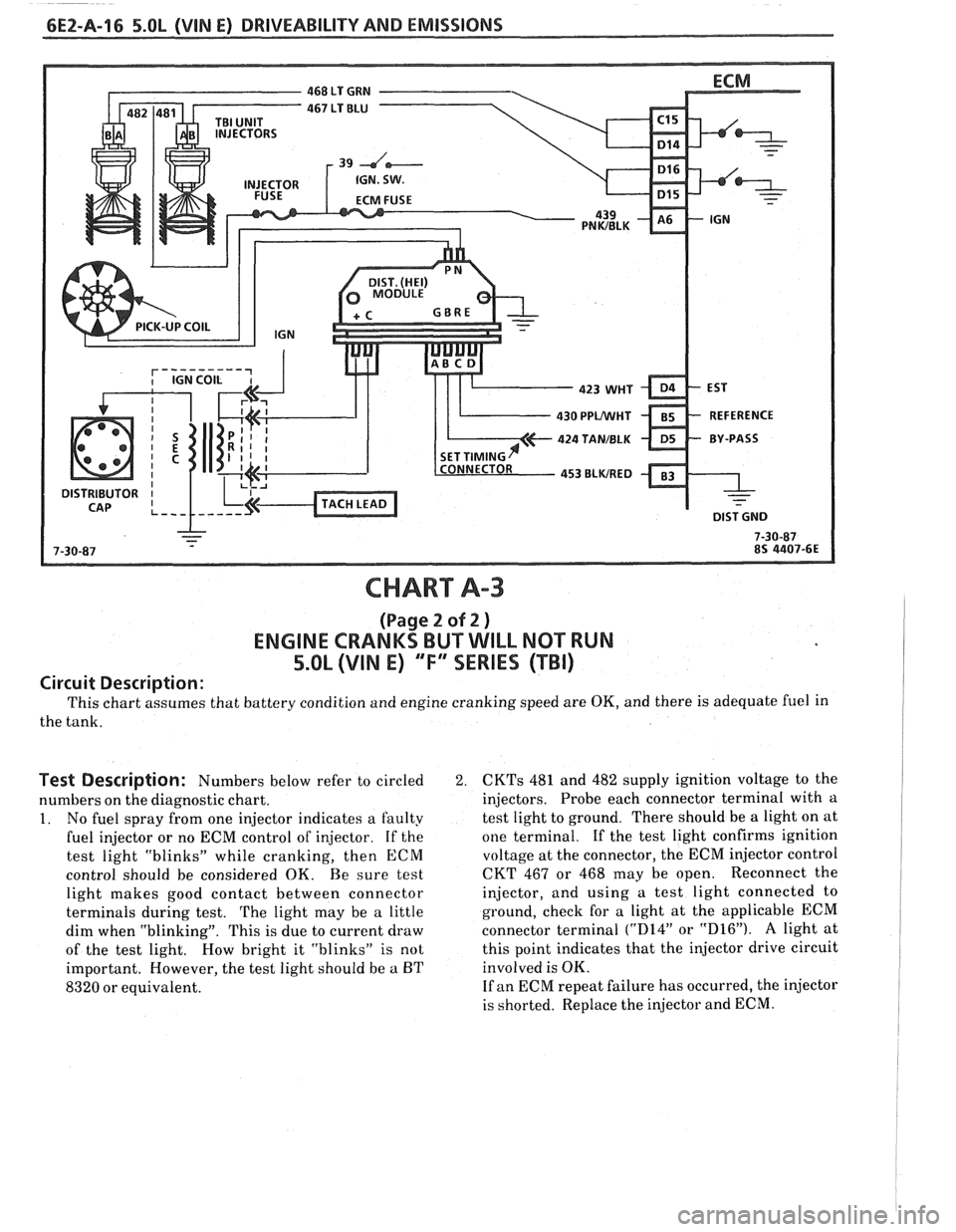
CHART A-3
(Page 2 of 2 )
ENGINE CRANKS BUT WILL NOT RUN
5.OL (VIN E) "F'XSERIES (TBI)
Circuit Description:
This chart assumes that battery condition and engine cranking speed are OK, and there is adequate fuel in
the tank.
Test Description: Numbers below refer to circled 2.
numbers on the diagnostic chart.
1. No fuel spray from one injector indicates a faulty
fuel injector or no ECM control of injector. If the
test light "blinks" while cranking, then
ECM
control should be considered OK. Be sure test
light makes good contact between connector
terminals during test.
The light may be a little
dim when "blinking". This is due to current draw
of the test light. How bright it "blinks" is not
important. However, the test light should be
a BT
8320 or equivalent.
CKTs 481 and 482 supply ignition voltage to the
injectors. Probe each connector terminal with a
test light to ground. There should be a light on at
one terminal.
If the test light confirms ignition
voltage at the connector, the ECM injector control
CKT 467 or 468 may be open. Reconnect the
injector, and using a test light connected to
ground, check for a light at the applicable ECM
connector terminal
("D14" or "D16"). A light at
this point indicates that the injector drive circuit
involved is OK.
If an ECM repeat failure has occurred, the injector
is shorted. Replace the injector and ECM.
Page 512 of 1825
DRIVEABILITY AND EMISSIONS 5.OL (VIN E) CEZ-A-21
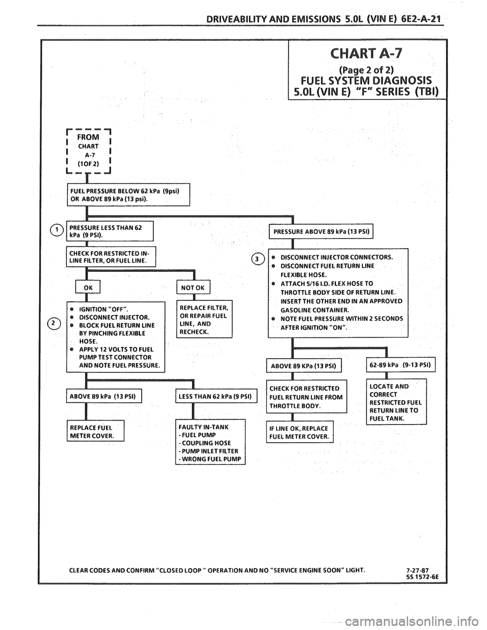
@ DISCONNECT FUEL RETURN LlNE
FLEXIBLE HOSE.
ATTACH
5/16 1.D. FLEX HOSE TO
THROTTLE BODY SIDE OF RETURN LINE.
INSERT THE OTHER END IN AN APPROVED
GASOLINE CONTAINER.
r NOTE FUEL PRESSURE WITHIN 2 SECONDS
@ APPLY 12 VOLTS TO FUEL
CHECK FOR RESTRICTED
FUEL RETURN
LlNE FROM
THROTTLE BODY.
CLEAR CODES AND CONFIRM "CLOSED LOOP
" OPERATION AND NO "SERVICE ENGINE SOON" LIGHT.
Page 530 of 1825
DRIVEABILITY AND EMISSIONS 5.OL (VIN E) 6EZ-A-39
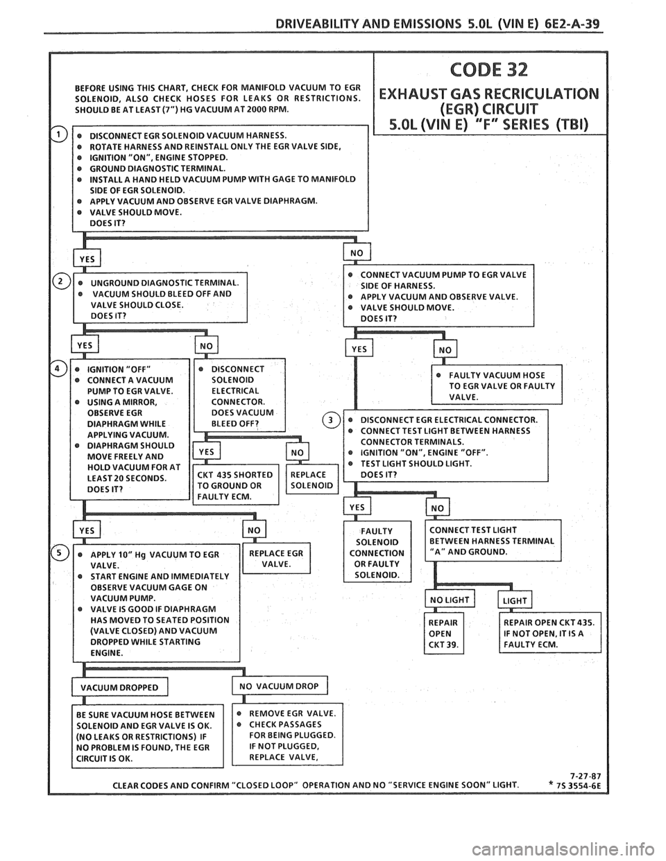
BEFORE USING THIS CHART, CHECK FOR MANIFOLD VACUUM TO EGR
@ GROUND DIAGNOSTIC TERMINAL. @ INSTALL A HAND HELD VACUUM PUMP WITH GAGE TO MANIFOLD
PUMP TO EGR VALVE.
@ USING A MIRROR,
OBSERVE EGR
DIAPHRAGM WHILE
APPLYING VACUUM.
DIAPHRAGM SHOULD OR
TERMINALS.
MOVE FREELY AND "ON",
ENGINE "OFF".
HOLD VACUUM FOR AT T
SHOULD LIGHT.
LEAST
20 SECONDS.
OBSERVE VACUUM GAGE ON
VACUUM PUMP.
HAS MOVED TO SEATED POSITION
CLEAR CODES AND CONFIRM "CLOSED LOOP"
OP
Page 537 of 1825
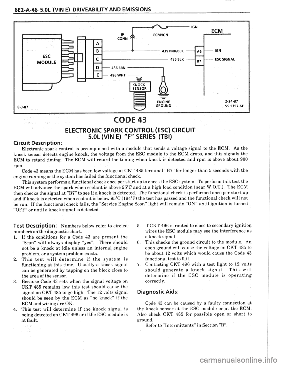
CODE 43
ELECTRONIC SPARK CONTROL (ESC) CIRCUIT
5.0L (VIN E) "F" SERIES (TBI)
Circuit Description:
Electronic spark control is accomplished with a module that sends a voltage signal to the ECM. As the
knock sensor detects engine knock, the voltage from the ESC module to the ECM drops, and this signals the
ECM to retard timing. The ECM will retard the timing when knock is detected and rpm is above about 900
rpm. Code 43 means the ECM has been low voltage at CKT 485 terminal
"B7" for longer than 5 seconds with the
engine running or the system has failed the functional check.
This system performs a functional check once per start up to check the ESC system. To perform this test the
ECM will advance the spark when coolant is above 95°C and at
a high load condition (near W.O.T.). The ECM
then checks the signal at
"B7" to see if a knock is detected. The functional check is performed once per start up
and if knock is detected when coolant is below 95°C (194°F) the test has passed and the functional check will not
be run. If the functional check fails, the "Service Engine Soon" light will
remain "ON" until ignition is turned
"OFF" or until a knock signal is detected.
Test Description: Numbers below refer to circled
numbers on the diagnostic chart.
1. If the conditions for a Code 43 are present the
"Scan" will always display "yes". There should
not be a knock at idle unless an internal engine
problem, or a system problem exists.
2. This test will determine if the system is
functioning at this time. Usually a
knock signal
can be generated by tapping on the block close to
the area of the sensor.
3. Because Code 43 sets when the signal voltage on
CKT 485 remains low this test should cause the
signal on CKT 485 to go high. The
12 volts signal
should be seen by the ECM as "no knock"
it' the
ECM and wiring are OK.
4.
This test will determine if the knock signal is
being detected on CKT 496 or if the ESC module is
at fault. 5.
If
CKT 496 is routed to close to secondary ignition
wires the ESC
module may see the interference as
a knock signal.
6. This checks the ground circuit to the module. An
open ground will cause the voltage on CKT 485 to
be about
12 volts which would cause the Code 43
functional test to fail.
7. Contacting
CKT 496 with a test light to
12 volts
should generate a knock signal.
This will
determine if the ESC nodule is operating
correctly.
Diagnostic Aids:
Code 43 can be caused by a faulty connection at
the knock sensor at the ESC
lnodule or at the ECM.
Also check CKT 485 for possible open or short to
ground.
Iiefer to "Intcrmittents" in Section "B".
Page 549 of 1825
6EZ-B-2 5.OL (VIN E) DRIVEABILITY AND EMISSIONS
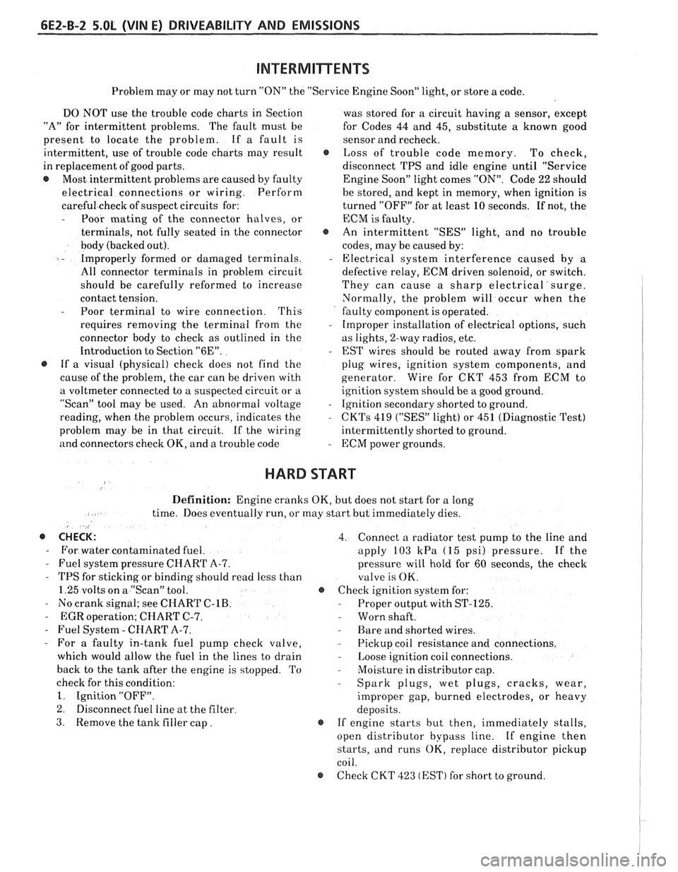
Problem may or may not turn "ON" the "Service Engine Soon" light, or store a code.
DO NOT use the trouble code charts in Section
"A" for intermittent problems. The fault must be
present to locate the problem. If a fault is
intermittent, use of trouble code charts may result
in replacement of good parts.
@ Most intermittent problems are caused by faulty
electrical connections or wiring. Perform
careful check of suspect circuits for:
- Poor mating of the connector halves, or
terminals, not fully seated in the connector
body (backed out).
I - Improperly formed or damaged terminals.
All connector terminals in problem circuit
should be carefully reformed to increase
contact tension.
- Poor terminal to wire connection. This
requires removing the terminal from the
connector body to check as outlined in the
Introduction to Section
"6E".
@ If a visual (physical) check does not find the
cause of the problem, the car can be driven with
a voltmeter connected to a suspected circuit or a
"Scan" tool may be used. An abnormal voltage
reading, when the problem occurs, indicates the
problem may be in that circuit. If the wiring
and connectors check OK, and a trouble code was
stored for a circuit having a sensor, except
for Codes 44 and 45, substitute a known good
sensor and recheck.
@ Loss of trouble code memory. To check,
disconnect TPS and idle engine until "Service
Engine Soon" light comes
"ON". Code 22 should
be stored, and kept in memory, when ignition is
turned "OFF" for at least 10 seconds. If not, the
ECM
is faulty.
@ An intermittent "SES" light, and no trouble
codes, may be caused by:
- Electrical system interference caused by a
defective relay, ECM driven solenoid, or switch.
They can cause a sharp electrical surge.
Normally, the problem will occur when the
faulty component is operated.
- Improper installation of electrical options, such
as lights, 2-way radios, etc.
- EST wires should be routed away from spark
plug wires, ignition system components, and
generator. Wire for CKT 453 from ECM to
ignition system should be a good ground.
- Ignition secondary shorted to ground.
- CKTs 419 ("SES" light) or 451 (Diagnostic Test)
intermittently shorted to ground.
- ECM power grounds.
HARD START
Definition: Engine cranks OK, but does not start for a long
time. Does eventually run, or may start but immediately dies.
, <
@ CHECK: 4. Connect a radiator test pump to the line and
- For water contaminated fuel. apply 103 kPa (15 psi) pressure. If the
- Fuel system pressure CHART A-7. pressure will hold for 60 seconds, the check
- TPS for sticking or binding should read less than
valve is OK.
1.25 volts on a "Scan" tool. @ Check ignition system for:
- No crank signal; see CHART C-1B. - Proper output with ST-125.
- EGR operation; CHART C-7. - Worn shaft.
- Fuel System - CHART A-7. - Rare and shorted wires.
- For a faulty in-tank fuel pump check valve, - Pickup coil resistance and connections.
which would allow the fuel in the lines to drain
- Loose ignition coil connections.
back to the tank after the engine is stopped. To
- Moisture in distributor cap.
check for this condition:
- Spark plugs, wet plugs, cracks, wear,
1. Ignition "OFF".
improper gap, burned electrodes, or heavy
2. Disconnect fuel line at the filter
deposits.
3. Remove the tank filler cap. @ If engine starts but then, immediately stalls,
open distributor bypass line. If engine then
starts, and runs OK, replace distributor pickup
coil.
@ Check CKT 423 (EST) for short to ground.
Page 555 of 1825
6EZ-C-1 5.OL (VIN E) DRIVEABILITY AND EMISSIONS
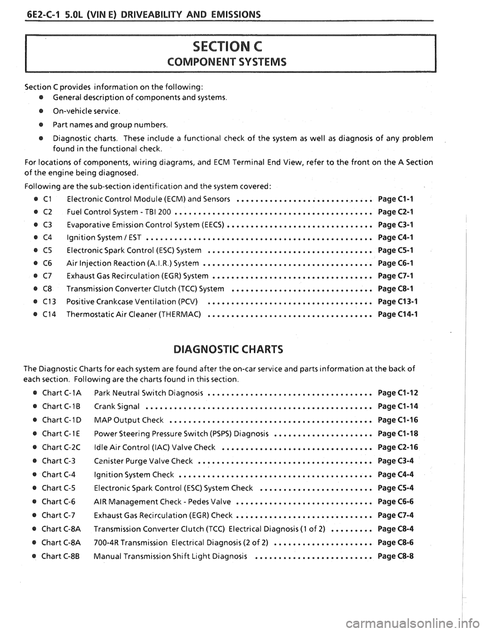
Section C provides information on the following:
@ General description of components and systems.
@ On-vehicle service.
@ Part names and group numbers.
@ Diagnostic charts. These include a functional check of the system as well as diagnosis of any problem
found in the functional check.
For locations of components, wiring diagrams, and ECM Terminal End View, refer to the front on the A Section
of the engine being diagnosed.
Following are the sub-section identification and the system covered:
@ C1 Electronic Control Module (ECM) and Sensors ............................. Page C1-1
@ C2 Fuel Control System - TBI 200 .......................................... Page C2-1
Evaporative Emission Control System (EECS) ...............................
Ignition System 1 EST ................................................
Electronic Spark Control (ESC) System ...................................
Air Injection Reaction (A.I.R.) System ....................................
Exhaust Gas Recirculation (EGR) System ..................................
Transmission Converter Clutch (TCC) System ..............................
Positive Crankcase Ventilation (PCV) ...................................
Thermostatic Air Cleaner (THERMAC) ...................................
BIAGNOSIIC CHARTS
Page C3-1
Page C4-1
Page C5-1
Page C6-1
Page C7-1
Page C8-1
Page C13-1
Page C14-1
The Diagnostic Charts for each system are found after the on-car service and parts information at the back of
each section. Following are the charts found in this section.
@ Chart C-1A Park Neutral Switch Diagnosis ................................... Page C1-12
@ Chart C-1B Crank Signal ................................................ Page C1-14
@ Chart C-1 D MAP Output Check ........................................ Page C1-16 I
..................... @ Chart C-1 E Power Steering Pressure Switch (PSPS) Diagnosis Page C1-18 1
................................ @ Chart C-2C Idle Air Control (IAC) Valve Check Page C2-16 !
..................................... @ Chart C-3 Canister Purge Valve Check Page C3-4 I
@ Chart C-4 Ignition System Check ......................................... Page C4-4
........................ @ Chart C-5 Electronic Spark Control (ESC) System Check Page C5-4
- ............................. @ Chart C-6 AIR Management Check Pedes Valve Page C6-6
............................. Chart C-7 Exhaust Gas Recirculation (EGR) Check Page C7-4
@ Chart C-8A Transmission Converter Clutch (TCC) Electrical Diagnosis (1 of 2) ......... Page C8-4 I
@ Chart C-8A 700-4R Transmission Electrical Diagnosis (2 of 2) ..................... Page C8-6 I
......................... @ Chart C-8B Manual Transmission Shift Light Diagnosis Page C8-8
Page 556 of 1825
DRIVEABILITY AND EMISSIONS 5.OL (VIN El 6EZ-C1-1
SECTION Cl
ELECTWONllC CONTROL MODULE (ECM) AND SENSORS
CONTENTS
GENERAL DESCRIPTION . . . . . . . . . . . . . . . C1-1 Coolant Temperature Sensor . . . . . . . . C1-5
ELECTRONIC CONTROL MODULE (ECM) . . C1-1 MAT Sensor. . . . . . . . . . . .. . . ... . . . . $1 -5
PROM ........................... C1-1 MAP Sensor. . . . . . . . . . . . . . . . . . . . . . C1 -6
CALPAK.........,................ C1-2 Oxygen (02) Sensor. . . . . . ... . . . a C1-6
ECM FUNCTION . . . , . . . . . . . . . . . . . . . . C1-2 Throttle Position Sensor (TPS) . . . . . . . . C1-6
INFORMATION SENSORS . . . . . . . . . . . . . C1-2 Vehicle Speed Sensor (VSS) . . . . . . . . . C1-6
Engine Coolant Temperature Sensor . . C1-2 PIN Switch. . . . . . . . . . . . . . . . . . . . . . . C1-6
MAP Sensor. . . . . . . . . . . . . . . . . . . . . . C1-2 (PSPS) . . . . . ... .. . . . ... . . .. .. . . . C1-6
MAT Sensor. . . . . . . . . . . . . . . . . . . . . . C1-3 AJC Request Signal . . . . . . . . . . . . . . . . C1-6
Oxygen (Oz) Sensor. . . . . . . . . .. . . . . . C1-3 Distributor Reference Signal . . . . . . . . . C1-6
Throttle Posit~on Sensor (TPS) . . . . . . . . C1-3 Knock Signal . . . . . . . . . . . . . . . . . . . C1-6
Knock Sensor . . . . . . . . . . . . . . . . . . . . C1-4 ON-CAR SERVICE . . . . . . . . . . . . . . . . . . . . . C1-6
Park Neutral Switch (Auto Only) . . . . . . C1-4 ELECTRONIC CONTROL MODULE . . . . . . . 61-6
Crank Signal . . . . . . , . . . . . . . . . . . . . . C1-4 PROM ........................... C1-7
A/C "On" Signal . . . , . . . . . . . . . . . . . . C1-4 Functional Check . . . . . . . . . . . . . . . . . C1-8
Vehicle Speed Sensor (VSS) . . . . . . . . . C1-4 CALPAK...................,...... C1-8
Distributor Reference Signal . . . . . . . . . C1-4 COOLANTSENSOR .. . . . . . . . , . . . . . . . . . C1-9
(PSPS) . . . . . . . . . . . . . . . . . . . . . . . . . C1-4 MAPSENSOR ..... ........ ... . .. . .* C1-9
DIAGNOSIS . . . . . . . . . . . . . . . . . . . . . . . . . C1-5 OXYGEN (02) SENSOR . . . . . . . . . a . . a . . C1-9
ECM ............................. C1-5 THROTTLE POSITION SENSOR (TPS) . . . . . C1-10
PROM ........................... C1-5 PARKINEUTRALSWITCH . . . . . . . . . . . . . . C1-10
ECM INPUTS.. . . . . . . . . . . . . . . . , . . . . . C1-5 PARTS
INFORMATION . . . . . . . . . . . . . . . . . C1-10
GENERAL DESCRIPTION
ELECTRONIC CONTROL MODULE (ECM)
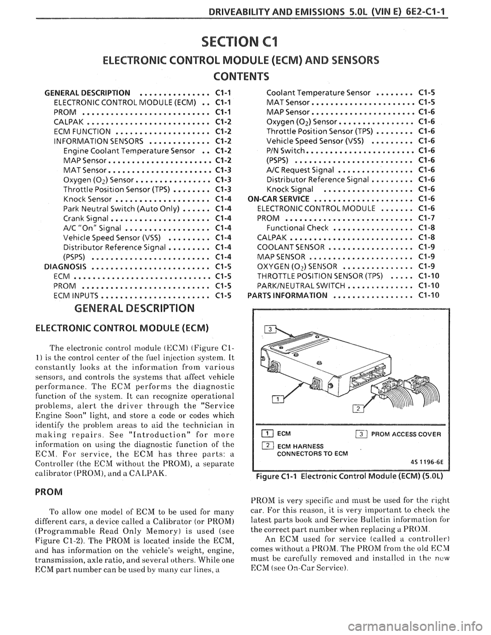
The electronic control module (KCMI (Figure C1-
1) is the control center of the fuel ir!jection system. It
constantly looks at the information from various
sensors, and controls the systems that affect vehicle
performance. The ECM performs the diagnostic
function of the system. It can recognize operational
problems, alert the driver through the "Service
Engine Soon" light, and store a code or codes which
identify the problem areas to aid the technician in
making repairs. See "Introduction" for more
information on using the diagnostic function of the
ECM. For service, the ECM has three parts:
a
Controller (the ECM without the PROM), a separate
calibrator (PROM), and a
CALPAK.
To allow one model of ECM to be used for many
different cars, a device called a Calibrator (or PROM)
(Programmable Read Only Memory) is used (see
Figure
C1-2). The PROM is located inside the ECM,
ancl has information on the vehicle's weight, engine,
transmission, axle ratio, and several others. While one
ECM part number can be used by many car lines, a
ECM PROM ACCESS COVER
1 ECM HARNESS
CONNECTORS TO ECM
45 1196-6E
Figure C1-1 Electronic Control Module (ECM) (5.OL)
PROM is very specific and must be used for the right
car. For this reason, it is very important to checlc the
latest parts book and Service Bulletin information for
the correct part number when replacing
a PROM.
An ECM used for service (called a controller)
comes without a
PROM. The PROM from the old blC>1
must be carefully removed and installctl in the new
EChI (see On-Car Service).
Page 563 of 1825
6E2-C1-8 5.OL (VIM E) DRIVEABILITY AND EMISSIONS
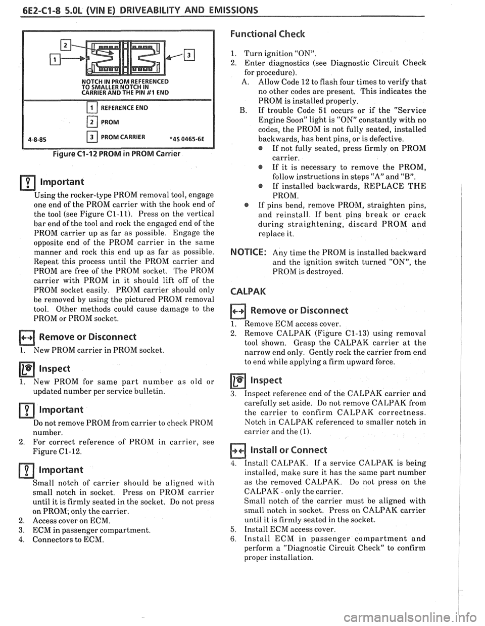
NOTCH IN PROM REFERENCED
TO SMALLER NOTCH IN
CARRIER AND THE PIN
#I END
REFERENCE END
PROM
PROM CARRIER *4S 0465-6E
Figure 61-12 PROM in PROM Carrier
lmportant
Using the rocker-type PROM removal tool, engage
one end of the PROM carrier with the hook end of
the tool (see Figure
C1-11). Press on the vertical
bar end of the tool and rock the engaged end of the
PROM carrier up as far as possible. Engage the
opposite end of the PROM carrier in the same
manner and rock this end up as far as possible.
Repeat this process until the PROM carrier and
PROM are free of the PROM socket. The PROM
carrier with PROM in it should lift off of the
PROM socket easily. PROM carrier should only
be removed by using the pictured PROM removal
tool. Other methods could cause damage to the
PROM or PROM socket.
Remove or Disconnect
1. New PROM carrier in PROM socket
Inspect
1. New
PROM for same part number as old or
updated number per service bulletin.
Important
Do not remove PROM from carrier to check PROM
number.
2. For correct
reference of PROM in carrier, see
Figure
C1-12.
important
Small notch of carrier should be aligned with
small notch in socket. Press on
PROM carrier
until it is firmly seated in the socket. Do not press
on PROM; only the carrier.
2. Access cover on ECM.
3. ECM in passenger compartment.
4. Connectors to ECM.
Functional Check
1. Turn ignition "ON".
2. Enter diagnostics (see Diagnostic Circuit Check
for procedure).
A. Allow Code 12 to flash four times to verify that
no other codes are present. This indicates the
PROM is installed properly.
B. If trouble Code 51 occurs or if the "Service
Engine Soon" light is "ON" constantly with no
codes, the PROM is not fully seated, installed
backwards, has bent pins, or is defective.
@ If not fully seated, press firmly on PROM
carrier.
If it is necessary to remove the PROM,
follow instructions in steps "A" and
"B".
@ If installed backwards, REPLACE THE
PROM.
@ If pins bend, remove PROM, straighten pins,
and reinstall. If bent pins break or crack
during straightening, discard PROM and
replace it.
NOTICE: Any time the PROM is installed backward
and the ignition switch turned "ON", the
PROM is destroyed.
CALPAK
n Remove or Disconnect
1. Remove ECM access cover.
2. Remove
CALPAK (Figure
C1-13) using removal
tool shown. Grasp the CALPAK carrier at the
narrow end only. Gently rock the carrier from end
to end while applying a firm upward force.
Inspect
3. Inspect reference end of the CALPAK carrier and
carefully set aside. Do not remove CALPAK from
the carrier to confirm CALPAK correctness.
Notch in CALPAK referenced to smaller notch in
carrier and the
(1).
a Install or Connect
4. Install CALPAK. If a service CALPAK is being
installed, make sure it has the same part number
as the removed CALPAK. Do
not press on the
CALPAK
- only the carrier.
Small notch of the carrier must be aligned with
small notch in socket. Press on CALPAK carrier
until it is firmly seated in the socket.
5. Install ECM access cover.
6. Install ECM in passenger compartment and
perform a "Diagnostic Circuit Check" to confirm
proper installation.