1988 PONTIAC FIERO ignition
[x] Cancel search: ignitionPage 1434 of 1825
DRIVER INFORMATION CENTER (DIC)
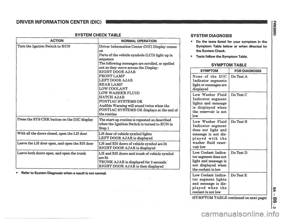
SYSTEM CHECK TABLE
ACTION NORMAL OPERATION
Press the SYS CHK button on the DIC display
With
all the doors closed, open the LH door
Leave the LH door open, and open the RH door
Leave both doors open, and open the
t
Driver Information Center (DIC) Display comes
on
Parts of the vehicle symbols (LCD) light up
in
sequence
The following messages are scrolled, or spelled
out as they move across the Display:
RIGHT DOOR AJAR
FRONT LAMP
LEFT DOOR AJAR
REAR LAMP
LOW COOLANT
LOW WASHER FLUID
HATCH AJAR
PONTIAC SYSTEMS OK
Audible Warning will sound twice when the
PONTIAC SYSTEMS OK displays at the end of
the routine
The start-up routine is repeated as described
when the Ignition Switch is turned to RUN
in - Step 1
LH door of vehicle symbol lights
LEFT DOOR AJAR
is displayed
LH and RH doors of vehicle symbol are
lit
RIGHT DOOR AJAR is displayed
LH and RH doors and trunk of vehicle symbol
are lit
TRUNK AJAR is displayed for
2 seconds '
RIGHT DOOR AJAR is then displayed
0 Refer to System Diagnosis when a result is not normal.
SYSTEM DlAGNOSlS
Do the tests listed for your symptom in the
Symptom Table below or when directed by
the System Check.
Tests follow the Symptom Table.
SYMPTOM TABLE
ights and message
s displayed when
he reservoir is not
ed with the
er fluid
reser-
(SYMPTOM TABLE continued on next page)
Page 1435 of 1825
DRIVER INFORMATION CENTER (DlC)
(SYMPTOM TABLE continued from previous (Continued
from previous column) (Continued from
previous column)
page) Taillamp Outage Check the PPL (905)
Indicator segment wire and printed cir-
SYMPTOM TABLE does not light and cuit for an open
message is not dis-
If OK, replace the
played when a lamp Lights Monitor
is out Module
One of the Door Ajar Do Test
N
segments lights and
message is displayed
when that door is
closed
If OK, replace the
(904) wire
and printed
(Continued in next column)
me Door Ajar I Do Test I 1
segments does not
light
and message is
not displayed with
I that door open
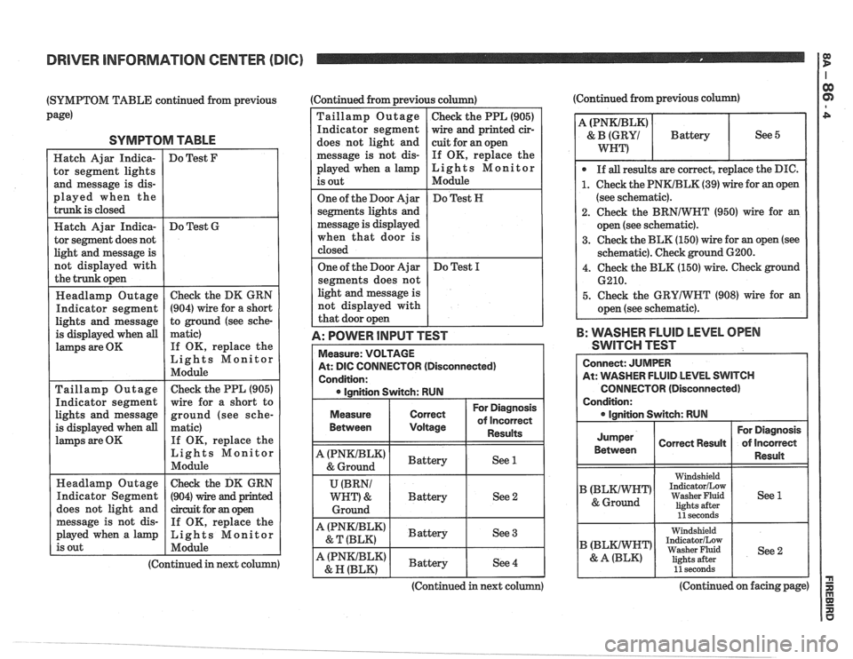
A: POWER lRlPUT TEST
Measure: VOLTAGE
At:
DlC CONNECTOR (Disconnected)
Condition: ignition Switch: RUN
For Diagnosis
Measure
Between
Correct of incorrect
Voltage Results
A (PNKIBLK) Battery & Ground See 1
U (BRNI
WRT) & Battery
See 2
Ground
A (PNKlBLK) Battery & T (BLK) See 3
A (PNKIBLK) Battery & R
(BLK) See 4
2. Check
the BRNlWHT (950) wire for an
open (see schematic).
3. Check the BLK (150) wire for an open (see
schematic). Check ground
G200.
4. Check the BLK (150) wire. Check ground
B: WASHER FLUID LEVEL OPEN
SWITCH TEST
Connect: JUMPER
At: WASHER FLUID LEVEL SWITCH
CONNECTOR (Disconnected)
Condition:
For Diagnosis
Jumper Correct Result of
lncorrect
1 Between 1 Resun 1 I
I Windshield 1 1 IndicatorILow
) 1 Washer Fluid 1 See1 lights after llseconds I
Washer Fluid See 2
I I 11 seconds [ I
(Continued in next co (Continued on facing page)
Page 1436 of 1825
DRIVER INFORMATION CENTER (DIC)
(Continued from facing page)
@ If both tests are good, replace the Washer
Fluid Level Switch.
1. Check the BLKIWHT (99) wire for an
open (see schematic).
2. Check the BLK (152) wire for an open (see
schematic).
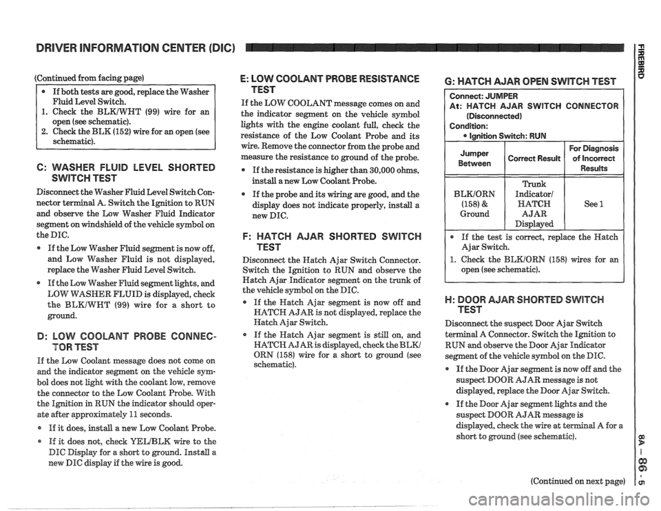
6: WASHER FLUID LEVEL SHORTED
SwlTen TEST
Disconnect the Washer Fluid Level Switch Con-
nector
terminal A. Switch the Ignition to RUN
and observe the Low Washer Fluid Indicator
segment on windshield of the vehicle symbol on
the
me.
If the Low Washer Fluid segment is now off,
and Low Washer Fluid is not displayed,
replace the Washer Fluid Level Switch.
If the Low Washer Fluid segment lights, and
LOW
VirASHER FLUID is displayed, check
the
BLKIWWT (99) wire for a short to
ground.
B: LOW COOLANT PROBE CONNEC-
TOR TEST
If the Low Coolant message does not come on
and the indicator segment on the vehicle sym-
bol does not light with the coolant low, remove
the connector to the Low Coolant Probe. With
the Ignition in RUN the indicator
should oper-
ate after approximately
11 seconds.
If it does,
install a new Low Coolant Probe.
* If it does not, check YELIBLM wire to the
DIC Display for a short to ground. Install a
new DIC display if the wire is good.
E: LOW COOLANT PROBE RESISTANCE
TEST
If the LOW COOLANT message comes on and
the indicator segment on the vehicle symbol
lights with the engine coolant full, check the
resistance of the Low Coolant Probe and its
wire. Remove the connector from the probe and
measure the resistance to ground of the probe.
If the resistance is higher than 30,000 ohms,
instdl a new Low Coolant Probe.
If the probe
and its wiring are good, and the
display does not indicate properly, install a
new DIC.
F: HATCH AJAR SHORTED SWITCH
TEST
Disconnect the Hatch Ajar Switch Connector.
Switch the Ignition to RUN and observe the
Hatch Ajar Indicator segment on the trunk of
the vehicle symbol on the DIC.
If the Hatch Ajar segment is now off and
HATCH AJAR is not displayed, replace the
Hatch Ajar Switch.
o If the Hatch Ajar segment is still on, and
HATCH AJAR is displayed, check the
BLKl
ORN (158) wire for a short to ground (see
schematic).
6: WATCH AJAR OPEN SWITCH TEST
R SWITCH CONNECTOR
1. Check the BEKIORN (158) wires for an
open (see schematic).
)-I: BOOR AJAR SHORTED SWITCH
TEST
Disconnect the suspect Door Ajar Switch
a1 A Connector. Switch the Ignition to
RUN and observe the Door Ajar
Indieator
segment of the vehicle symbol on the DIC.
@ If the Door Ajar segment is now off and the
suspect DOOR AJAR message is not
displayed, replace the Door Ajar Switch.
If the Door Ajar segment lights and the
suspect DOOR
AJAR message is
displayed, check the wire at
terminal A for a
short to ground (see schematic).
(Continued on next page)
Page 1441 of 1825
(Continued from previous page)
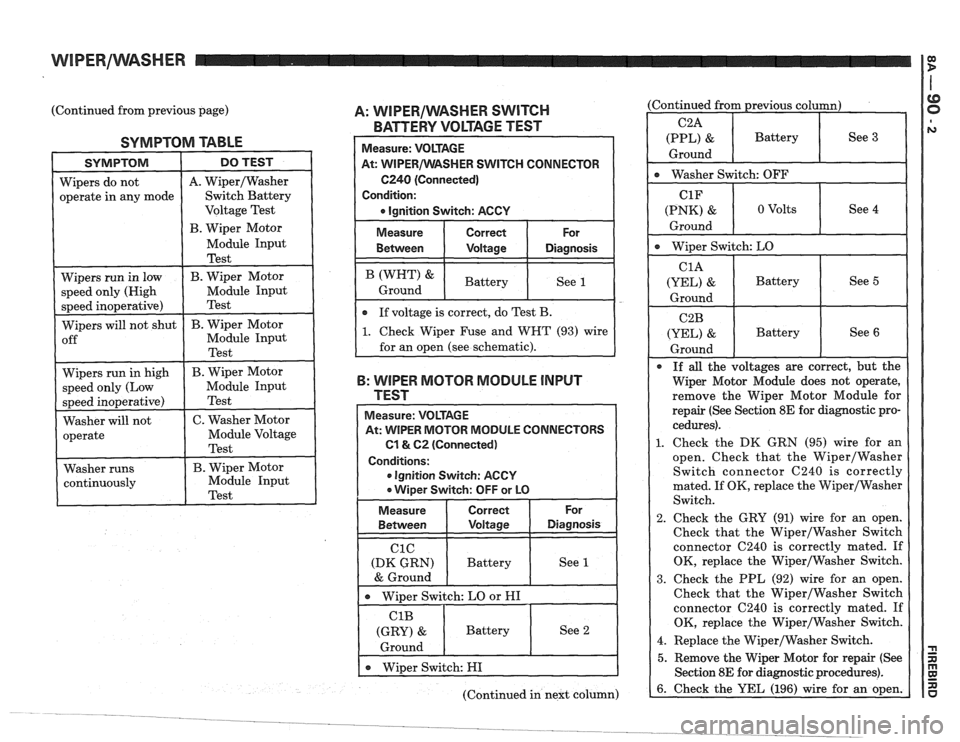
SYMPTOM TABLE
A. WiperIWasher
A: WIPERIWASHER SWITCH
BATTERY VOLTAGE TEST
R SWITCH CONNECTOR
6240 (Connected)
(Continued from previous column)
ClF
(PNK) & 0 Volts See 4
Ground
- -
( Wiper Switch: LO
CIA
(mL) & Battery See 5
Ground
B: WIPER MOTOR MODULE lNPUT
TEST remove the Wiper Motor Module for
repair (See Section
8E for diagnostic pro-
1. Check the DK GRN (95) wire for an
open. Check that the
WiperIWasher
Switch connector 6240 is correctly
mated. If OK, replace the
WiperlWasher
(Continued in next column)
Measure: VOLTAGE
At: WIPER MOTOR IVIODULE CONNECTORS
C1& 62 (Connected)
Conditions:
e Ignition Switch: ACCY
Wiper Switch: OFF or LO
2. Check the GRY (91) wire for an open.
Check that the
WiperIWasher Switch
connector
6240 is correctly mated. If
OK, replace the WiperIWasher Switch.
3. Check the PPL (92) wire for an open.
Check that the
WiperIWasher Switch
connector
6240 is correctly mated. If
OK, replace the Wiper/Washer Switch.
4. Replace the
WiperIWasher Switch.
5. Remove the Wiper Motor for repair (See
For
Diagnosis
See 1
Measure
Between
C1C
(DK GRN)
& Ground
Correct
Voltage
Battery
e Wipes Switch: LO or HI
C1B
(GRY) &
Ground
e Wiper Switch: HI
Battery
See 2
Page 1442 of 1825
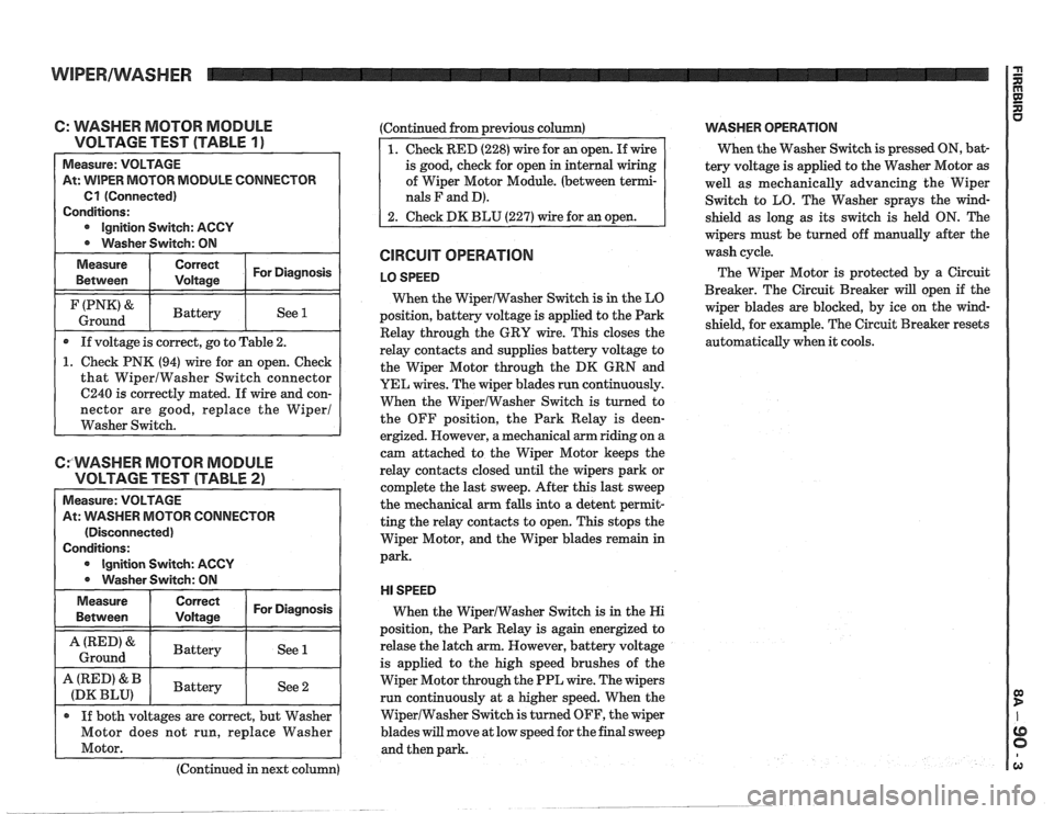
C: WASHER MOTOR MODULE
VOLTAGE TEST (TABLE
1 ) -
Measure: VOLTAGE
At: WIPER MOTOR MODULE CONNECTOR
Cl (Connected)
Conditions:
Ignition Switch: ACCY
Washer Switch: ON
Measure Correct For Diagnosis
Between Voltage
I (PNK'& I Battery I See 1 I Ground
If voltage is correct, go to Table 2.
1. Check PNK (94) wire for an open. Check
that WiperlWasher Switch connector
6240 is correctly mated. If wire and con-
nector are good, replace the Wiper1
Washer Switch.
CfWASHER MOTOR MODULE
VOLTAGE TEST (TABLE
2)
Measure: VOLTAGE
At:
VVASHER MOTOR CONNECTOR
(Disconnected)
Conditions:
Ignition Switch: ACCY
0 Washer Switch: ON
Measure
Between
I ::::ii 1 For Diagnosis I
I A(RED'& I Battery I See 1 I Ground
A (RED' & Battery
(DK BLU) See 2
If both voltages are correct, but Washer
Motor does not run, replace Washer
Motor.
(Continued in next column) (Continued
from previous column)
of Wiper Motor Module. (between
terrni-
nals F and D).
CIRCUIT OPERATION
LO SPEED
When the WiperlWasher Switch is in the LO
position, battery voltage is applied to the Park
Relay through the GRY wire. This closes the
relay contacts and supplies battery voltage to
the Wiper Motor through the DK GRN and
YEL wires. The wiper blades run continuously.
When the WiperIWasher Switch is turned to
the OFF position, the Park Relay is
deen-
ergized. However, a mechanical arm riding on a
cam attached to the Wiper Motor keeps the
relay contacts closed until the wipers park or
complete the last sweep. After this last sweep
the mechanical arm falls into a detent
perrnit-
ting the relay contacts to open. This stops the
Wiper Motor, and the Wiper blades remain in
park.
HI SPEED
When the WiperIWasher Switch is in the Hi
position, the Park Relay is again energized to
relase the latch arm. However, battery voltage
is applied to the high speed brushes of the
Wiper Motor through the PPL wire. The wipers
run continuously at a higher speed. When the
WiperlWasher Switch is turned OFF, the wiper
blades
will move at low speed for the final sweep
and then park.
VVASHER OPERATION
When the Washer Switch is pressed ON, bat-
tery voltage is applied to the Washer Motor
as
well as mechanically advancing the Wiper
Switch to LO. The Washer sprays the wind-
shield as long as its switch is held ON. The
wipers must be turned off manually after the
wash cycle.
The Wiper Motor is protected by a Circuit
Breaker. The Circuit Breaker
will open if the
wiper blades are blocked, by ice on the wind-
shield, for example. The Circuit Breaker resets
automatically when it cools.
Page 1445 of 1825
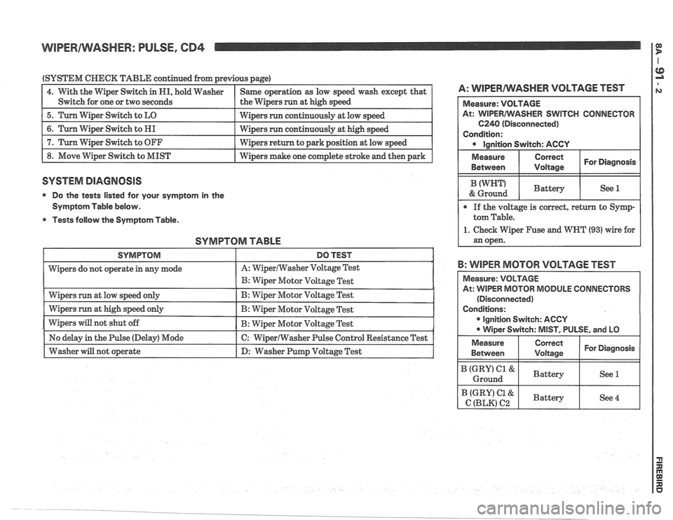
WIPERIWASHER: PULSE, CD4 1 g
(SYSTEM CHECK TABLE continued from previous page)
1 4. With the Wiper Switch in HI, hold Washer I Same operation as low speed wash except that I A: WlPERAlVASHER VOLTAGE TEST
I Switch for one or two seconds I the Wipers run at high speed I
1 5. Turn Wiper Switch to LO I wipers run continuously at low speed I
1 8. Move Wiper Switch to MIST I Wipers make one complete stroke and then park I
6. Turn Wiper Switch to HI
7. Turn Wiper Switch to OFF
SYSTEM DIAGNOSIS
Wipers run continuously at high speed
Wipers return to park position at low speed
@ Do the tests listed for your symptom in the
Symptom Table below.
Tests
dollovv the Symptom Table.
SYMPTOM TABLE
SWITCH CONNECTOR
B: WIPER MOTOR VOLTAGE TEST
ODULE CONNECTORS
(Disconnected)
r ignition Switch: AGCY
Page 1446 of 1825
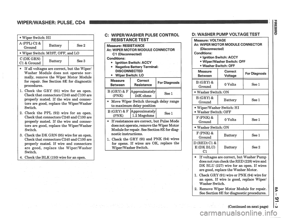
WIPERNVASHER: PULSE, CD4
Washer Module does not operate nor-
1. Check the GRY (91) wire for an open.
Check that connectors C240 and
C1OO are
properly mated. If the wire and connec-
tors are good, replace the
VViperlWasher
2. Check the PPL (92) wire for an open.
Check that connectors C240 and
ClOO are
6: WIPERIWASHER PULSE CONTROL D: WSHER PUMP VOLTAGE TEST
RESISTANCE TEST
At: WIPER MOTOR MODULE CONNECTOR
GI (Disconnected)
Ignition Switch:
ACCY
Negative Battery Terminal:
DlSCONNECTED
does not operate, remove the Wiper Motor
Module for repair. See Section
8E for diag-
nostic
instmctions.
1. Check the GRU (91) and PNK (94) wires
for opens. If wires are OK, replace the
WiperlWasher Switch.
ODULE CONNECTOR
ignition Switch: AGCV
are good, replace the Washer Motor.
1. Check GRU (91) wire or PNK (94) wire for
an open. If wire is good, replace Wiper1
Washer Switch.
(Continued on next page)
Page 1475 of 1825
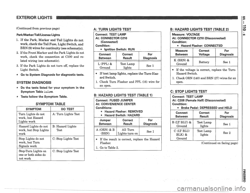
EXTERIOR LlGHTS
(Continued from previous page)
Park/MarkerflaIl/License UgMs
1. If the Park, Marker and Tail Lights do not
work, cheek the Tail Fuse, Light Switch, and
BRN (9) wires for continuity (see schematic).
2. If the Front Marker and the Park Lights dd not
work, check the connection at 6100 and re-
lated wiring (see schematic).
3. If the Park Lights do not turn off, replace the
Light Switch.
s Go to System Diagnosis for diagnostic tests.
@ Do the tests listed for your symptom in the
Symptom
Able bezaw.
@ Tests follow the Symptom Table.
SYMPTOM arABhE
A: TURN LIGHTS TEST
SYMPTOM
Turn Lights do not
work, but Hazard
Lights work
Hazard Lights do not
work, but Stop Lights
work
Stop Lights do not
work, but Turn
Signals work
Stop-Turn Lights on
one or both sides do
not work
B: HAZARD LIGHTS TEST (TABLE 2)
DO TEST
A: Turn Lights Test
B: Hazard Lights
Test
6: Stop Lights Test
6: Stop Lights Test
Connect: TEST LAMP
At: CONNECTOR C210
(Connected)
Condition:
Ignition Switch: RUN
o If the result is correct, replace the Hazard
Flasher.
1. Go to Table 2.
B: HAZARD LIGHTS TEST (TABLE 1)
Connect: FUSED JUMPER
At: CONVENIENCE
CENTER
Conditions:
r Hazard Flasher: REMOVED
Hazard Switch:
HAZARD
Measure: VOLTAGE
At: CONNECTOR 621 0 (Disconneded)
Condition:
Hazard Flasher: CONNECTED
For
Diagnosis
See 1
Connect
Between
L (PPL) &
Ground
I Measure ( Correct ( For
e If test lamp lights, replace the
ard Switch.
1. Check Turn Flasher and PPE (16) wire for
an open.
Correct
Result
Test Lamp
lights
For
Diagnosis
See 1
Jumper
Between
A (QRN) & B
(BRN)
Between I Voltage I Diagnosis
Correct Result
All Turn
Lights turn on
( If the voltage is correct, replace the Turn- I
(BRN) &
Ground
Hazard Switch.
1. Check ORN (140) and BRN (27) wires for an
open.
6: STOP LIGHTS TEST
At: 6208 (Fernale Half) (Disconnected)
Condition:
Brake Pedal: DEPRESSED and HELD
Battery See 1
Connect
Behvveen
I CEKyy 1 Test Lamp
lights I See 2 I
B (LT BLU) &
Ground
I Ground I I I
Correct
Result
(Continued on facing page)
For
Diagnosis
Test Lamp
lights See 1