1988 PONTIAC FIERO ignition
[x] Cancel search: ignitionPage 1411 of 1825
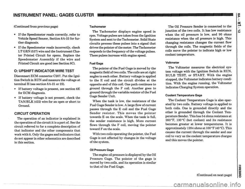
(Continued from previous page)
If the Speedometer reads correctly, refer to
Vehicle Speed Sensor, Section
8A-33 for fur-
ther diagnosis.
If the Speedometer reads incorrectly, check
LT GRN (537) wire and the Instrument Clus-
ter Printed Circuit for opens. Replace the
Speedometer Assembly if the wire and
Printed Circuit are good (see Section
8C).
O: UPSHIFT INDICATOR WIRE TEST
Disconnect ECM connector C207. Put the Igni-
tion Switch in RUN and measure the voltage at
terminal
H (see section 8A-21 or 22).
If battery voltage is present, see section
6E
for ECM diagnosis.
If battery voltage is not present, check the
TANIBLK (422) wire for an open or short to
Ground.
CIRCUIT OPERATION
The operation of an indicator is explained in
the operation of the circuit it is apart of. See the
circuit referred to for a complete description of
that indicator and the other components that
work with it. Only the gages and indicators that
do not appear in other schematics are described
in this section.
Tachometer
The Tachometer displays engine speed in
rpm. Voltage pulses are taken from the Ignition
System and sent to the Tachometer. Solid State
circuits process these pulses into a signal that
drives the pointer of the meter. The Tachometer
responds to the frequency of the voltage pulses.
These pulses increase with engine speed.
Fuel Gage
The pointer of the Fuel Gage is moved by the
magnetic field of two coils. The coils are at right
angles to each other. Battery voltage is applied
to the E coil and the circuit divides at the
opposite end of this coil. One path continues to
ground through the F coil. Another goes to
ground through the variable resistor of the Fuel
Gage Sender Unit.
When the tank is low, the resistance of the
Fuel Gage Sender is low. A large flow of current
passes through the E coil and the Fuel Gage
Sender resistor. This moves the pointer
towards E on the scale. When the tank is
full,
the sender resistance is high. More current
flows through the F coil, moving the pointer
toward F on the scale.
With two coils operating the pointer, the Fuel
Gage is not affected by changes in the voltage
of the system.
011 Pressure Gage
The engine oil pressure is displayed by the Oil
Pressure Gage. The pointer of the gage is
moved by two coils, and its operation is similar
to that of the Fuel Gage. The
Oil Pressure Sender is connected to the
junction of the two coils.
It has low resistance
when the oil pressure is low, and 90 ohms
resistance when the oil pressure is high. This
changing resistance changes the current flow
through the coils. The magnetic fields of the
coils move the pointer to indicate high or low
coolant temperature.
Voltmeter
The Voltmeter measures the electrical sys-
tem voltage with the Ignition Switch in RUN,
BULB TEST, or START. With the engine
stopped, the Voltmeter indicates battery condi-
tion. With the engine
running, the Voltmeter
indicates Charging System operation.
Coolant Temperature Gage
The Coolant Temperature Gage is also oper-
ated by two coils. Battery voltage is applied to
both coils. One is grounded directly
and the
other is grounded through the Coolant Tem-
perature Sender. This has 54 ohms resistance at
260
OF, 130 "C (hot coolant) and its resistance
becomes greater at lower temperatures. It is
appr~ximately 1284 ohms at 100 OF (40 '6). This
causes the current through the sender and one
coil to vary as the coolant temperature charges
and this moves the pointer.
Page 1420 of 1825
INSTRUMENT PANEL: DIGITAL CLUSTER a
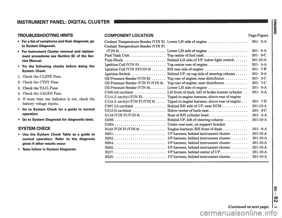
TROUBLESHOOTING HINTS COMPONENT LOCATION u Page-Figure
0 For a list of symptoms and their diagnosis. go
to System Diagnosis
.
0 For Instrument Cluster removal and replace-
ment procedures see Section
86 of the Ser-
vice Manual
.
* Try the following checks before doing the
System Check
.
1 . Check the CLSTR Fuse .
2 . Check the CTSY Fuse .
3 . Check the TAIL Fuse .
Coolant Temperature Sender (VIN E) Lower LH side of engine ....................
Coolant Temperature Sender (VIN F)
(VIN 8)
........................ Lower LH side of engine ....................
Fuel Tank Unit .................. Top center of fuel tank ......................
Fuse Block ...................... Behind LH side of IIP. below light switch .......
Ignition Coil (VIN E) ............. Top center rear of engine ....................
Ignition Coil (VIN F)(VIN 8) ....... RH rear side of engine ......................
Ignition Switch .................. Behind IIP. on top side of steering column ......
Oil Pressure Sender (VIN E) ....... Top rear of engine. near distributor ............
Oil Pressure Sender (VIN F) (VIN 8) . Top rear of engine. near distributor ............
Oil Pressure Sender (VIN S) ........ Lower LH side of engine ....................
................ .. 4 . Check the GAGES Fuse . el00 (42 cavities) LH
front of dash. left of brake master cylinder 201- 0-A
C114
(1 cavity) (VIN E) ............ Taped to engine harness. above rear of engine
5 . If more than one indicator is out. check the C114 (1 cavity) (VIN F) (VIN 8) ..... Taped to engine harness. above rear of engine ... 201- 7-B
battery voltage inputs . . C207 (15 cavities) ................ Behind RH side of IIP near ECM ............. 201-13-A
................. .................... * Go to System Check for a guide to C313 (3 cavities) Below
center of back seat 201- 9-C operation . 6118 (VIN F) (VIN 8) ............. Rear of RH cylinder head .................... 201- 5-A
0 Go to System Diagnosis for diagnostic tests . 6200 .......................... Behind IIP. left of steering column ............ 201-10-A
6304
.......................... Under rear seat. on support bracket
SYSTEM CHECK S143 (VIN F) (VIN 8) ............. Engine harness. RH front of dash ............. 201- 6-A
0 Use the System Check able as a guide to S201 ........................... IIP harness. behind instrument cluster ......... 201-10-A
normal operation . Refer to the diagnosis S203 ........................... I/P harness. behind instrument cluster ......... 201-10-A
........................... ......... given if other results occur . S204 IIP harness. behind instrument cluster 201-10-A
........................... ......... Tests follow in System Diagnosis . S205 IIP harness. behind instrument cluster 201-10-A
S217 ........................... IIP harness. behind center of IIP .............. 201-10-A
S225 ........................... IIP harness. behind instrument cluster ......... 201-10-A
(Continued on next page)
Page 1421 of 1825
INSTRUMENT PANEL: DIGITAL CLUSTER 1 fE!
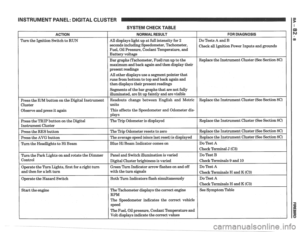
SYSTEM CHECK TABLE
FOR DIAGNOSIS
Do Tests A and B
Check
all Ignition Power Inputs and grounds
Replace the Instrument Cluster (See Section
8C)
ACTION
Turn the Ignition Switch to RUN
Observe and press it again
Replace the Instrument Cluster (See Section
8C)
The Speedometer indicates the correct vehicle
The Fuel, Oil pressure, Coolant Temperature and
Volt displays indicate the correct values I I I
NORMAL RESULT
All displays light up at full intensity for 2
seconds including Speedometer, Tachometer,
Fuel, Oil Pressure, Coolant Temperature, and
Battery voltage
Bar graphs (Tachometer, Fuel) run up to the
maximum and back again and then display their
present readings
All other displays use a segment pointer that
runs from bottom to top and back again and
then displays their present readings
Segments of the bar graphs that are not fully
illuminated, are
lit up faintly and are visible
Page 1424 of 1825
INSTRUMENT PANEL: DIGITAL CLUSTER
(Continued from previous page)
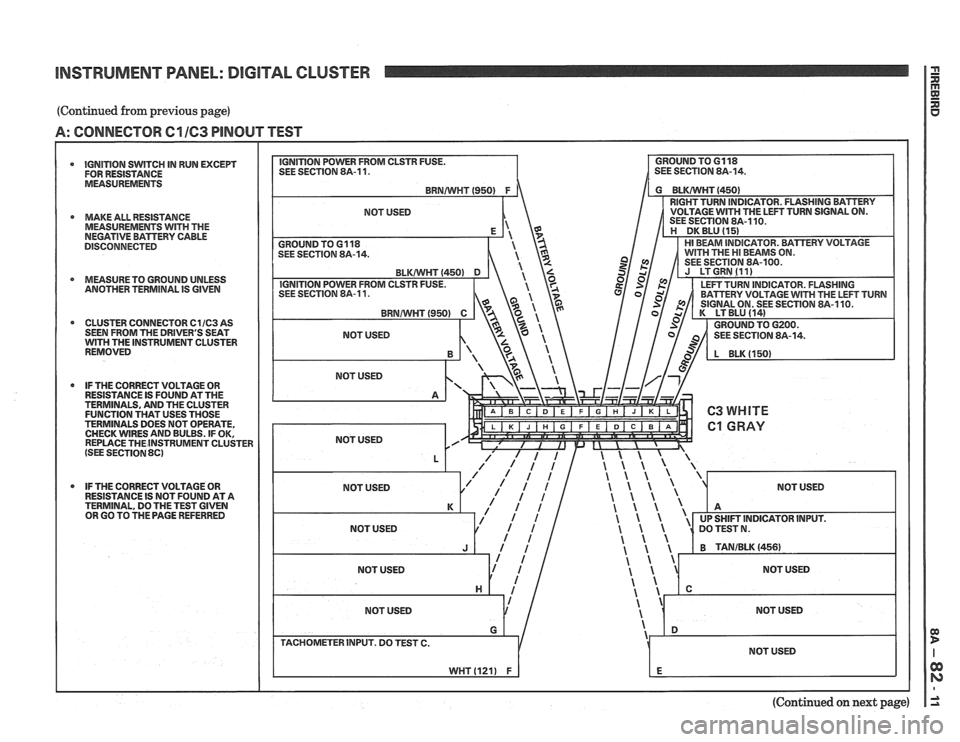
A: CONNECTOR C1 163 PINOUT TEST
IGNITION SWITCH IN RUN EXCEPT
FOR RESISTANCE
MEASUREMENTS
* MAKE ALL RESISTANCE
MEASUREMENTS WITH THE
NEGATIVE BAmERV CABLE
DISCONNECTED
4 MEASURETO GROUND UNLESS
ANOTHER TERMlNAL IS GIVEN
CLUSTER CONNECTOR
C11C3 AS - - - - . -. . - - . . . . - - . - . . - . . - - . . - SEEN FROM THE DRIVER'S SEAT WITH THE INSTRUMENT CLUSTER
REMOVED
* IF THE CORRECT VOLTAGE OR
RESISTANCE IS FOUND AT THE
TERMINALS, AND THE CLUSTER
FUNCTION THAT USES THOSE
TERMINALS DOES NOT OPERATE,
CHECK WIRES AND BULBS. IF OK,
REPLACE THEINSTRUMENT CLUSTER
(SEE SECTION 8C)
IF THE CORRECT VOLTAGE OR
RESISTANCE IS NOT FOUND AT A
TERMINAL, DO THE TEST GIVEN
OR GO TO
TI-IE PAGE REFERRED
NOT USED
(Continued on next page)
Page 1425 of 1825
INSTRUMENT PANEL: DIGITAL CLUSTER
(Continued from previous page)
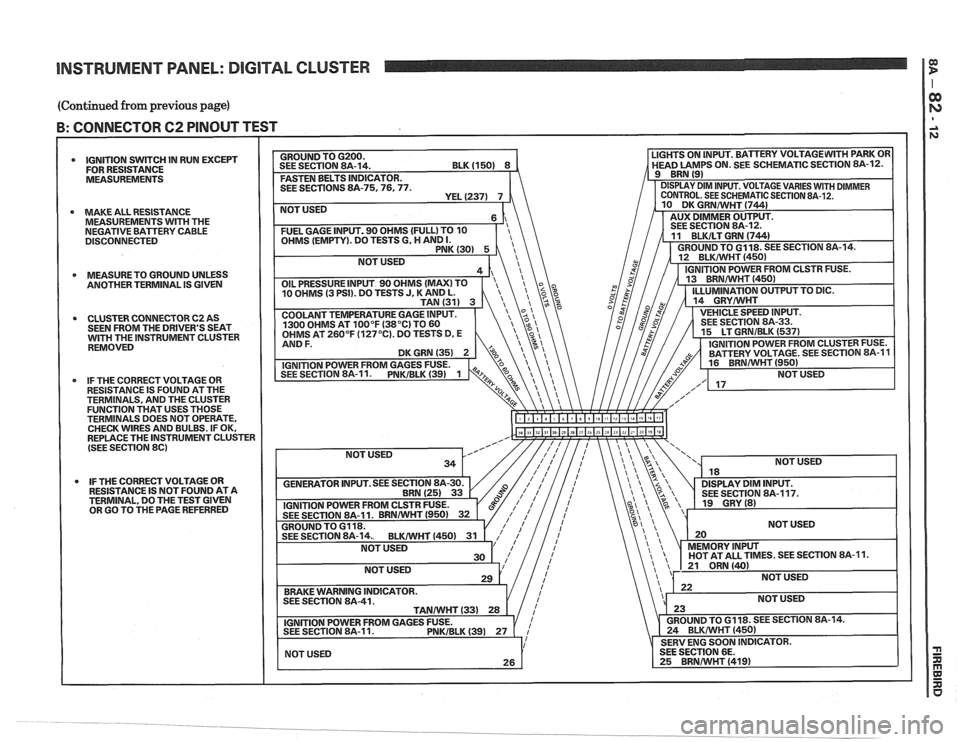
B: CONNECTOR 62 PINOUT TEST I I
IGNITION SWITCH IN RUN EXCEPT
FOR RESISTANCE
MEASUREMENTS
MAKE ALL RESISTANCE
MEASUREMENTS
WITH THE
NEGATIVE BATTERY CABLE
DISCONNECTED
MEASURETO GROUND UNLESS
ANOTHER TERMINAL IS
GIVEN
CLUSTER CONNECTOR C2 AS
SEEN FROM THE DRIVER'S SEAT
GH THE INSTRUMENT CLUSTER
REMOVED
IF THE CORRECT VOLTAGE OR
RESISTANCE IS FOUND AT THE
TERMINALS, AND THE CLUSTER
FUNCTION THAT USES THOSE
TERMINALS DOES NOT OPERATE,
CHECK WIRES AND BULBS. IF OK,
REPLACE THE INSTRUMENT CLUSTER
(SEE SECTION
86)
IF THE CORRECT VOLTAGE OR
RESISTANCE IS NOT FOUND AT A
TERMINAL, DO THE TEST GIVEN
OR GO TO THE PAGE REFERRED SEE
SECTIONS 8A-75.76,
NOT USED
ES. SEE SECTION 8A-11.
Page 1426 of 1825
INSTRUMENT PANEL: DIGITAL CLUSTER
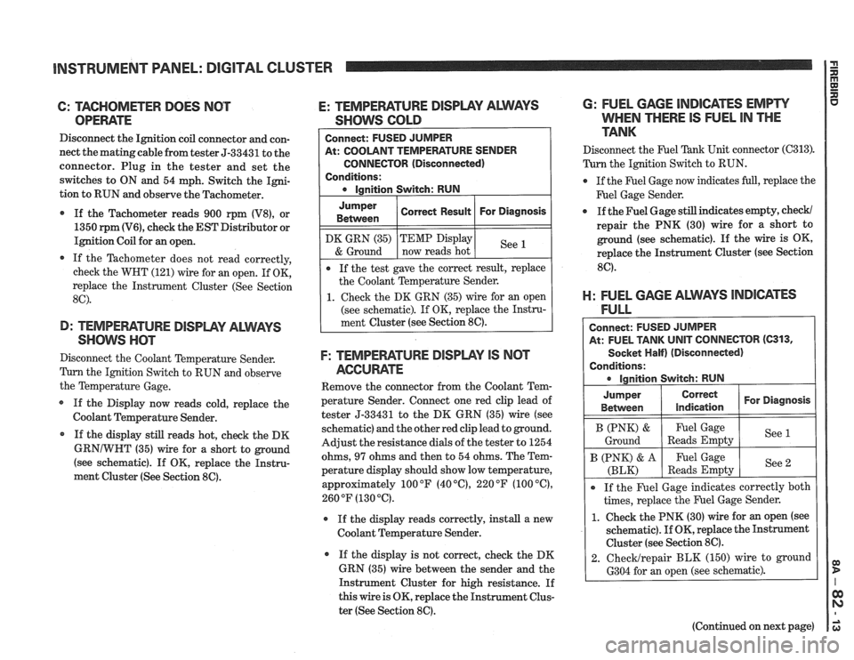
6: TAGHOMETER DOES NOT
OPEWTE
Disconnect the Ignition coil connector and con-
nect the matingcable from tester 5-33431 to the
connector. Plug in the tester and set the
switches to ON and 54 mph. Switch the Igni-
tion to RUN and observe the Tachometer.
If the Tachometer reads 900 rpm
(V8), or
1350
rpm (V6), check the EST Distributor or
Ignition Coil for an open.
If the Tachometer does not read correctly,
check the WHT (121) wire for an open. If OK,
replace the Instrument Cluster (See Section
8C).
D: TEMPEFIATURE DISPWY ALWAYS
SHOW nm
Disconnect the Coolant Temperature Sender.
Tum the Ignition Switch to RUN and observe
the Temperature Gage.
If the Display now reads cold, replace the
Coolant Temperature Sender.
* If the display still reads hot, check the DK
GRNIWHT (35) wire for a short to ground
(see schematic). If
OK, replace the Instru-
ment Cluster (See Section
86).
E: TEMPEFIATURE DISPLPIY ALMS
SHOWS GOLD
At: COOLANT TEMPERATURE SENDER
CONNECTOR (Disconnected)
Conditions:
Jumper
Between
F: TEMPEWTURE DISPWY IS NCIT
AGCUME
Remove the connector from the Coolant Tem-
perature Sender. Connect one red clip lead of
tester 5-33431 to the DK GRN (35) wire (see
schematic) and the other red clip lead to ground.
Adjust the resistance dials of the tester to 1254
ohms,
97 ohms and then to 54 ohms. The Tem-
perature display should show low temperature,
approximately 100
OF (40 "C), 220 OF (100 "C),
260 OF (130 "6).
r If the display reads correctly, install a new
Coolant Temperature Sender.
If the display is not correct, check the DK
GRN (35) wire between the sender and the
Instrument Cluster for high resistance. If
this wire is OK, replace the Instrument Clus-
ter (See Section
8C).
DK GRN (35)
& Ground
6: FUEL GAGE INDICATES EMPW
WHEN THERE IS FUEL IN THE
TANK
Correct Result
Disconnect the F'uel Tank Unit connector (C313).
Turn the Ignition Switch to RUN.
For Diagnosis
If the test gave the correct result, replace
the Coolant Temperature Sender.
1. Check the DK GRN (35) wire for an open
(see schematic). If OK, replace the Instru-
ment Cluster (see Section
8C).
TEMP Display
now reads hot
@ If the Fuel Gage now indicates full, replace the
F'uel Gage Sender.
See
a If the Fuel Gage still indicates empty, check/
repair the PNK (30) wire for a short to
ground (see schematic). If the wire is OK,
replace the Instrument Cluster (see Section
8C).
El: FUEL GAGE ALWAYS lNDl6ATES
FULL
Connect: FUSED JUMPER
At: FUEL TANK
UNIT CONNECTOR (C313,
Socket Half) (Disconnected)
Conditions: ignition Switch: RUN
I B (PNK) & I Fuel Gage I See (
Ground Reads Empty
Jumper
Between
If the Fuel Gage indicates correctly both
times, replace the Fuel Gage Sender.
1. Check the PNK (30) wire for an open (see
schematic).
If OK, replace the Instrument
Cluster (see Section
8C).
2. ChecMrepair BLK (150) wire to ground
6304 for an open (see schematic).
Correct
indication
B (PNK) & A
(BLK)
(Continued on next page)
For Diagnosis
Fuel Gage
Reads Empty See
2
Page 1427 of 1825
BNS'TWUMENT PANEL: DIGITAL CLUSTER a B
(Continued from previous gage)
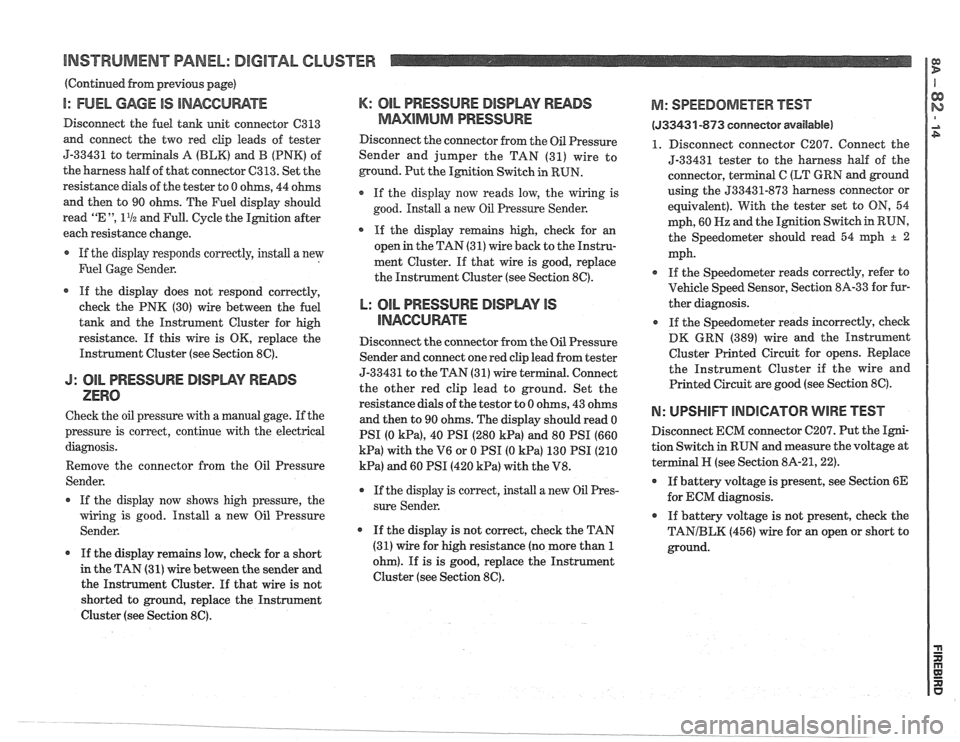
I: FUEL GAGE IS INACCUWTE
Disconnect the fuel tank unit connector C313
and connect the two red clip leads of tester
5-33431 to
terminals A (BLK) and B (PNK) of
the harness half of that connector
C313. Set the
resistance
dials of the tester to 0 ohms, 44 ohms
and then to 90 ohms. The Fuel display should
read
"E ", 11/2 and Full. Cycle the Ignition after
each resistance change.
If the display responds correctly, install a new
Fuel Gage Sender.
If the display does not respond correctly,
check the PNK (30) wire between the fuel
tank and the Instrument Cluster for high
resistance.
If this wire is OK, replace the
Instrument Cluster (see Section
8C).
J: OIL PRESSURE DISIDWY READS
ZERO
Check the oil pressure with a manual gage. If the
pressure is correct, continue with the electrical
diagnosis.
Remove the connector from the Oil Pressure
Sender.
If the display now shows high pressure, the
wiring is good. Install a new Oil Pressure
Sender.
If the display remains low, check for a short
in the TAN (31)
wire between the sender and
the Instrument Cluster. If that wire is not
shorted to ground, replace the Instrument
Cluster (see Section
8C).
K: OIL PRESSURE DISPWY RWDS
MMlMklM PRESSURE
Disconnect the connector from the Oil Pressure
Sender and jumper the TAN (31) wire to
ground. Put the Ignition Switch in RUN.
If the display now reads low, the wiring is
good. Install a new
Oil Pressure Sender.
* If the display remains high, check for an
open in the TAN (31) wire back to the Instru-
ment Cluster. If that wire is good, replace
the Instrument Cluster (see Section
8C).
L: OIL PRESSURE BlSPLAV IS
llUAGCll RATE
Disconnect the connector from the Oil Pressure
Sender and connect one red clip lead from tester
5-3343
1 to the TAN (3 1) wire terminal. Connect
the other red clip lead to ground. Set the
resistance dials of the
testor to 0 ohms, 43 ohms
and then to 90 ohms. The display should read 0
PSI (0
kPa), 40 PSI (280 kPa) and 80 PSI (660
kPa) with the V6 or 0 PSI (0 kPa) 130 PSI (210
kPa) and 60 PSI (420 kPa) with the V8.
r If the display is correct, install a new Oil Pres-
sure Sender.
If the display is not correct, check the TAN
(31) wire for high resistance (no more than
1
ohm). If is is good, replace the Instrument
Cluster (see Section
8C).
M: SPEEDOMETER BEST
(533431 -873 conneetor available)
1. Disconnect connector C207. Connect the
5-33431 tester to the harness
half of the
connector, terminal
C (LT GRN and ground
using the
533431-873 harness connector or
equivalent). With the tester set to
ON, 54
mph, 60
Hz and the Ignition Switch in RUN,
the Speedometer should read 54
qh + 2
mph.
If the Speedometer reads correctly, refer to
Vehicle Speed Sensor, Section
8A-33 for fur-
ther diagnosis.
If the Speedometer reads incorrectly, check
DK GRN (389) wire and the Instrument
Cluster Printed Circuit for opens. Replace
the Instrument Cluster if the wire and
Printed Circuit are good (see Section
8C).
N: UPSHIFT lNDlCATOR WIRE TEST
Disconnect ECM connector C207. Put the Igni-
tion Switch
in RUN and measure the voltage at
terminal
N (see Section 8A-21,221.
If battery voltage is present, see Section 6E
for ECM diagnosis.
If battery voltage is not present, check the
TANIBLK (456) wire for an open or short to
ground.
Page 1428 of 1825
INSTRUMENT PANEL: DIGITAL CLUSTER n 23 rn E
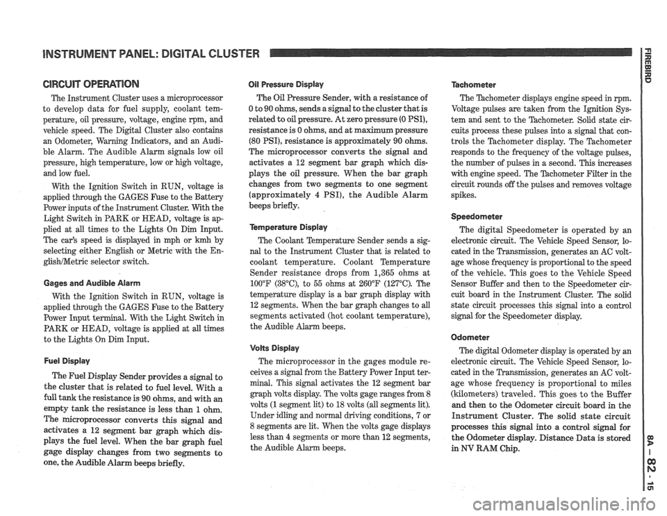
ClRCUlT OPERATION
The Instrument Cluster uses a microprocessor
to develop data for fuel supply, coolant tem-
perature, oil pressure, voltage, engine rpm, and
vehicle speed. The Digital Cluster also contains
an Odometer, Warning Indicators, and an Audi-
ble Alarm. The Audible Alarm signals low oil
pressure, high temperature, low or high voltage,
and low fuel.
With the Ignition Switch in RUN, voltage is
applied through the GAGES Fuse to the Battery
Power inputs of the Instrument Cluster. With the
Light Switch in PARK or HEAD, voltage is ap-
plied at all times to the Lights On Dim Input.
The car's speed is displayed in mph or
krnh by
selecting either English or Metric with the
En-
glishNetric selector switch.
Gages and Audible Alarm
With the Ignition Switch in RUN, voltage is
applied through the GAGES Fuse to the Battery
Power Input terminal. With the Light Switch in
PARK or HEAD, voltage is applied at all times
to the Lights On Dim Input.
Fuel Display
The Fuel Display Sender provides a signal to
the cluster that is related to fuel level. With a
full tank the resistance is 90 ohms, and with an
empty tank the resistance is less than
1 ohm.
The microprocessor converts this signal and
activates a 12 segment bar graph which dis-
plays the fuel level. When the bar graph fuel
gage display changes from two segments to
one, the Audible Alarm beeps briefly.
Oil Pressure Display
The Oil Pressure Sender, with a resistance of
0 to 90 ohms, sends a signal to the cluster that is
related
to oil pressure. At zero pressure (0 PSI),
resistance is 0 ohms, and at maximum pressure
(80 PSI), resistance is approximately 90 ohms.
The microprocessor converts the signal and
activates a 12 segment bar graph which dis-
plays the oil pressure. When the bar graph
changes from two segments to one segment
(approximately
4 PSI), the Audible Alarm
beeps briefly.
kmperature Display
The Coolant Temperature Sender sends a sig-
nal to the Instrument Cluster that is related to
coolant temperature. Coolant Temperature
Sender resistance drops from 1,365 ohms at
100°F
(38"C), to 55 ohms at 260°F (127°C). The
temperature display is a bar graph display with
12 segments. When the bar graph changes to all
segments activated (hot coolant temperature),
the Audible Alarm beeps.
Volts Display
The microprocessor in the gages module re-
ceives a signal from the Battery Power Input ter-
minal. This signal activates the 12 segment bar
graph volts display. The volts gage ranges from 8
volts
(1 segment lit) to 18 volts (all segments lit).
Under idling and normal driving conditions, 7 or
8 segments are lit. When the volts gage displays
less than
4 segments or more than 12 segments,
the Audible Alarm beeps.
Tachometer
The Thchometer displays engine speed in rpm.
Voltage pulses are taken from the
Ignition Sys-
tem and sent to the Tachometer. Solid state cir-
cuits process these pulses into a signal that con-
trols the Tachometer display. The Tachometer
responds to the frequency of the voltage pulses,
the number of pulses in a second. This increases
with engine speed. The
'Pdchometer Filter in the
circuit rounds off the pulses and removes voltage
spikes.
Speedometer
The digital Speedometer is operated by an
electronic circuit. The Vehicle Speed Sensor, lo-
cated in the Transmission, generates an AC volt-
age whose frequency is proportional to the speed
of the vehicle. This goes to the Vehicle Speed
Sensor Buffer and then to the Speedometer cir-
cuit board in the Instrument Cluster. The solid
state circuit processes this signal into a control
signal for the Speedometer display.
Odometer
The digital Odometer display is operated by an
electronic circuit. The Vehicle Speed Sensor, lo-
cated in the Transmission, generates an
AC volt-
age whose frequency is proportional to miles
(kilometers) traveled. This goes to the Buffer
and then to the Odometer circuit board in the
Instrument Cluster. The solid state circuit
processes this signal into a control signal for
the Odometer display. Distance Data is stored
in
NV RAM Chip.