1988 PONTIAC FIERO ignition
[x] Cancel search: ignitionPage 1548 of 1825
RADIO
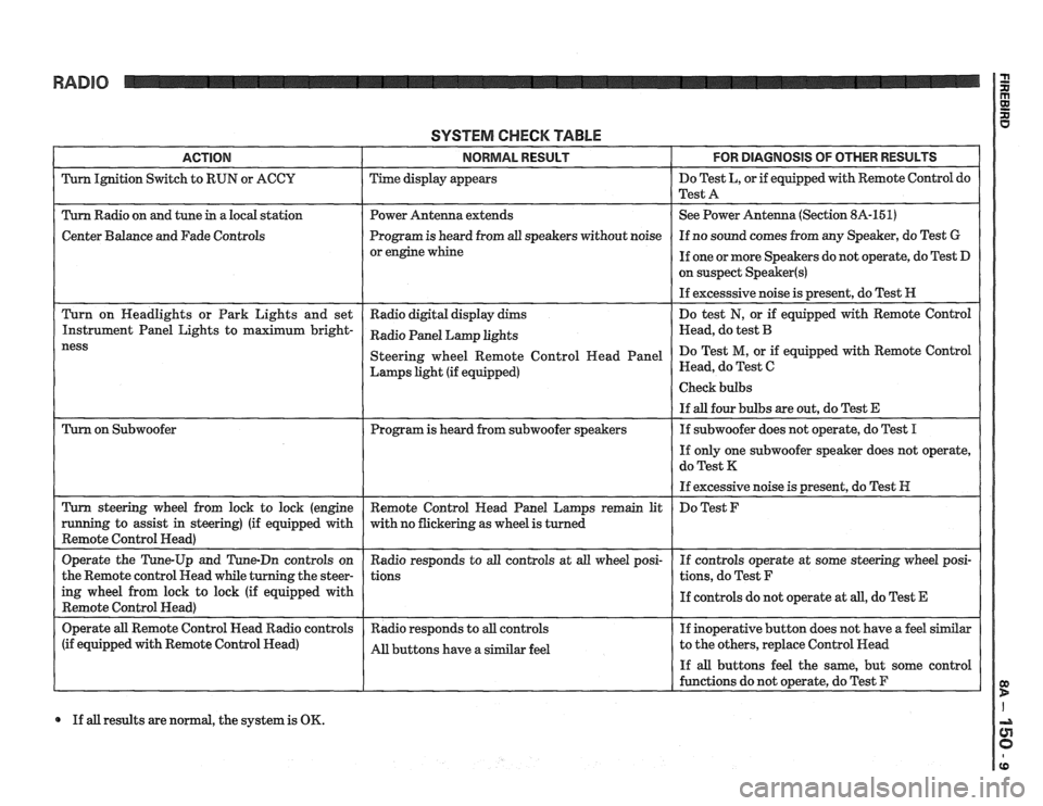
SYSTEM CHECK TABLE
ACTION NORMAL RESULT FOR DlAGNOSlS OF OTHER RESULTS
Turn Ignition Switch to RUN or ACCU Time display appears Do
Test L, or if equipped with Remote Control do
Test A
Turn Radio on and tune
in a local station Power Antenna extends See
Power Antenna (Section 8A-151)
Center Balance and Fade Controls Program
is heard from all speakers without noise If
no sound comes from any Speaker, do Test G
or engine whine
If one or more Speakers do not operate, do Test D
on suspect
Speaker(s)
If excesssive noise is present, do Test H
Turn on Headlights or Park Lights and set
Radio digital display dims Do
test
N, or if equipped with Remote Control
Instrument Panel Lights to maximum
bright- Radio Panel Lamp khts Head, do test B
Lamps light (if equipped) Head,
do Test C
If all results are normal, the system is OK.
Page 1550 of 1825
D: SPEAKER TEST (Continued from previous column)
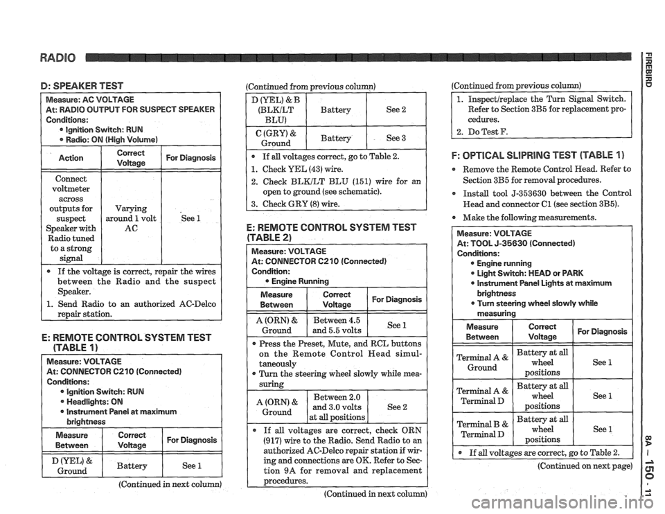
At: RADIO OUTPUT FOR SUSPECT SPEAKER
Ignition Switch: RUN
o an authorized AC-Delco
E: REMOTE CONTROL SYSTEM TEST
(TABLE
1)
Measure: VOLTAGE
At: CONNECTOR C210 (Connected)
Conditions: Ignition Switch: RUN
. Headlights: ON
I r Instrument Panel at maximum I brightness
I Measure I I For Diagnosis ( Between
I & I Battery I See 1 1 Ground I I I I
(Continued in next column)
D (YEL) & B
(BLKILT Battery See 2
BLU)
(GRY) & Battery
Ground See 3
If all voltages correct, go to Table
2.
1. Check YEL (43) wire.
2. Check BLKILT BLU (151) wire for an
open to ground (see schematic).
3. Check GRY
(8) wire.
E: REMOTE CONTROL SYSTEM TEST
(TABLE 2)
At: CONNECTOR 6210 (Connected)
Condition:
Measure
Between
I tz I For Diagnosis
1 I - I
A (ORN) & Between 4.5
Ground and 5.5 volts See 1
Press
the Preset, Mute, and RCL buttons
on the Remote Control
Head simul-
taneously
r Turn the steering wheel slowly while mea-
Between 2.0
at
all positions
If
all voltages are correct, check ORN
(917) wire to the Radio. Send Radio to an
authorized AC-Delco repair station if wir-
ing and connections are OK. Refer to Sec-
tion
9A for removal and replacement
~rocedures. ---- - -
(Continued in next column) (Continued from
previous
column)
Refer to Section 3B5 for replacement pro-
cedures.
2. DoTest F.
F: OPTlCAL SLlPRlNG TEST (TABLE 1 )
e Remove the Remote Control Head. Refer to
Section 3B5 for removal procedures.
r Install tool 5-353630 between the Control
Head and connector
C1 (see section 3B5).
Make the following measurements.
At: TOOL 5-35630 (Connected)
Engine running
0 Light Switch: MEAD or PARK
0 lnstrument Panel Lights at maximum
@ If all voltages are correct, go to Table 2.
(Continued on next page)
Page 1551 of 1825
RADIO
(Continued from previous page)
1. Remove the Cancel Cam. Inspect the Slip
Rings on the Cancel Cam and the spring
loaded contacts on the Turn Signal
Switch. Replace as necessary. Incorrect
or missinglubricant on the Cam can cause
premature failure. Take care to keep lubri-
cant or any foreign material away from
the
LED'S and receptors as it will hinder
or prevent proper operation. The correct
lubricant is part no.
26002312.
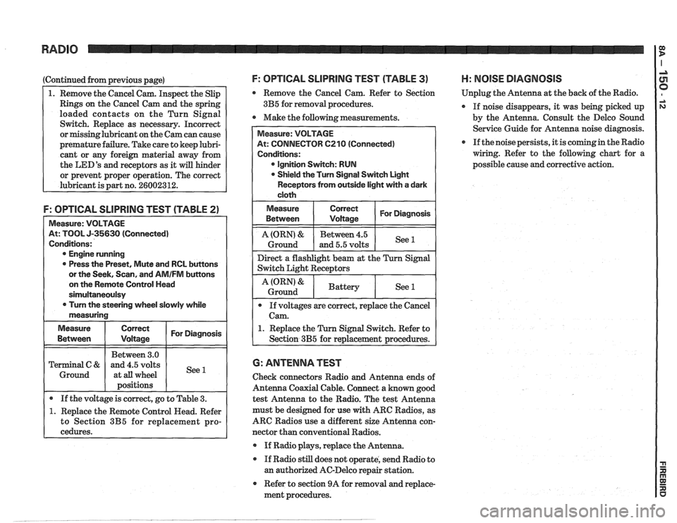
F: OPTICAL SLlPRlNG TEST (TABLE 2)
Measure: VOLTAGE
At: TOOL J-35630 (Connected)
Conditions:
@ Engine running
0 Press the Preset, Mute and RCL buttons
or the Seek, Scan, and
AMIFM buttons
on the Remote Control Head
sirnultaneoulsy
0 Turn the steering wheel slowly while
measuring
Measure
Correct I For Diagnosis I
I I Between 3.0 1 I Terminal C & and 4.5 volts
1 Ground 1 at all wheel
I 1 positions I I
I . If the voltage is correct, go to Table 3. (
1. Replace the Remote Control Head. Refer
to Section
3B5 for replacement pro-
cedures.
F: OPTICAL SLlPRllUG TEST (TABLE 3) H: NOlSE DIAGNOSIS
Remove the Cancel Cam. Refer to Section Unplug
the Antenna at the back of the Radio.
3B5 for removal procedures.
If noise disappears, it was being picked up
0 Make the following measurements.
by the Antenna. Consult the Delco Sound
Service Guide for Antenna noise diagnosis.
If the noise persists, it is coming in the Radio
wiring. Refer to the following chart for a
possible cause and corrective action.
At: CONNECTOR 6210 (Connected)
@ Ignition Switch: RUN
Shield the Turn Signal Switch Light
Receptors from outside light with a dark
1. Replace the Turn Signal Switch. Refer to
6: ANTENNA TEST
Check connectors Radio and Antenna ends of
Antenna Coaxial Cable. Connect a known good
test Antenna to the Radio. The test Antenna
must be designed for use
with ARC Radios, as
ARC Radios use a different size Antenna con-
nector than conventional Radios.
@ If Radio plays, replace the Antenna.
If Radio still does not operate, send Radio to
an authorized AC-Delco repair station.
Refer to section 9A for removal and replace-
ment procedures.
Page 1552 of 1825
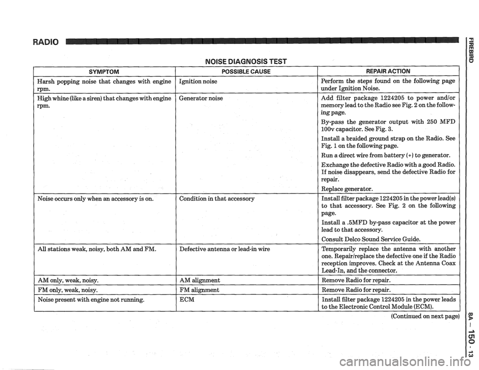
NOlSE DlAGNOSlS TEST
SYMPTOM I POSSIBLE CAUSE - - - - - - - - - - - -
Harsh popping noise that changes with engine Ignition
noise
rPm-
Nigh whine (like a siren) that changes with engine Generator
noise
rpm.
REPAIR ACTION
Perform the steps found on the following page
under Ignition Noise.
Add filter package 1224205 to power
and/or
memory lead to the Radio see Fig. 2 on the follow-
ing page.
By-pass the generator output with 250
MFD
1OOv capacitor. See Fig. 3.
Install a braided ground strap on the Radio. See
Fig.
1 on the following page.
I Run a direct wire from battery (+) to generator. I
Exchange the defective Radio with a good Radio.
If noise disappears, send the defective Radio for
repair.
Replace generator.
Noise occurs only when
an accessory is on. Condition in that accessory Install
filter package 1224205 in the power lead(s)
to that accessory. See Fig. 2 on the following
page-
Install a .5MFD by-pass capacitor at the power
lead to that accessory.
(Continued on next page)
Page 1553 of 1825
RADIO I
(Continued from previous page) from back of Radio
If noise persists with replacement antenna, the
problem must be repaired at the source of noise
(generator, ignition system, accessory, etc.). See
Delco Manual for noise "Sniffing" procedures.
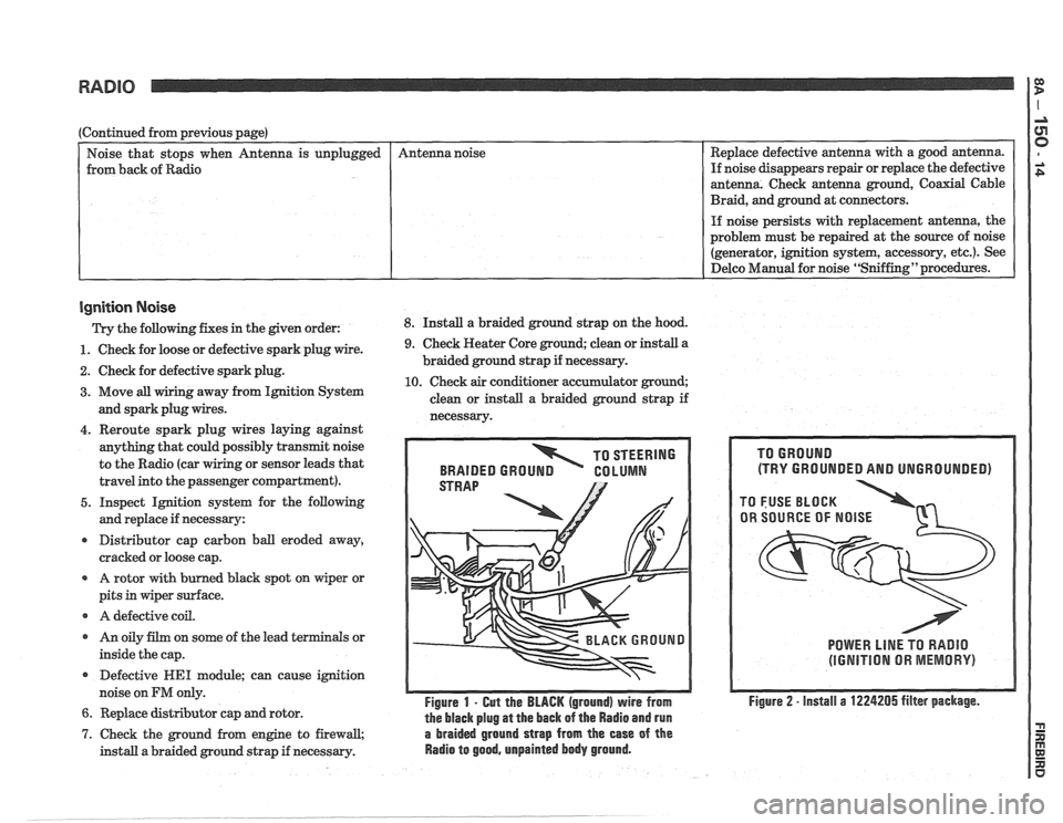
Ignition Noise
Trv the following. fixes in the piven order: 8. Install a braided ground strap on the hood. Replace
defective antenna with a good antenna.
If noise disappears repair or replace the defective
antenna. Check antenna ground, Coaxial Cable
Braid, and ground at connectors.
unplugged
- -
1. Check
for loose or defective spark plug wire.
2. Check for defective spark plug.
3. Move all wiring away from Ignition System
and spark plug wires. Antenna
noise
4. Reroute spark plug wires laying against
anything that could possibly transmit noise
to the Radio (car
g or sensor leads that
travel into the passenger compartment).
5. Inspect Ignition system for the following
and replace if necessary:
r Distributor cap carbon ball eroded away,
cracked or loose cap.
A rotor with burned black spot on wiper or
pits in wiper surface.
r A defective coil.
r An oily film on some of the lead terminals or
inside the cap.
Defective
WE1 module; can cause ignition
noise on
FM only.
6. Replace distributor cap and rotor.
9. Check Heater Core ground; clean or install a
braided ground strap if necessary.
10. Check air conditioner accumulator ground;
clean or install a braided ground strap if
necessarv.
TO STEERING
BRAIDED
GROUN GO LUMN
Figure 1 - Gut the BLACK (ground) wire from
the black plug
at the back of the Radio and run
7. Check the ground from engine to firewall, a braided ground strap from the ease of the
install a braided ground strap if necessary. Radio to good, unpainted body ground.
(TRY GROUNDED AND UNGROUNDED)
POWER LlNE TO RADIO
(IGNITION OR MEMORY)
Figure 2 - install a 1224205 filter package.
Page 1554 of 1825
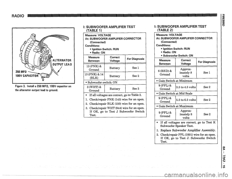
Figure 3. Install a 250 MFD, 100V capacitor on
the alternator output lead to ground.
I: SUBWOOFER AMPLIFIER TEST
(TABLE 19
2. Checklrepair BLK (150) wire for an open.
3. Checklrepair WRT (944) wire for an open.
If OK, go to Test J Subwoofer Switch
Test.
I: SUBWOOFER AMPLlFlER TEST
(TABLE
2)
Measure: VOLTAGE
At:
SUBWOOFER AMPLIFIER CONNECTOR
(Connected)
Conditions: Ignition
Svvitch: RUN
. Radio: ON
@ Subwoofer Switch: ON
Measure Correct
I Vdtaae I For Diagnosis
Between
Approx-
Grbund
Ground I See2 I -- -
Gain Switch at Mid Scale
0 Gain Switch at Maximum I Approx- (PPL' ' imately 8
Ground
volts
0 If all voltages are correct, go to Test K
Subwoofer Speaker Test.
1. Replace Subwoofer hplifier Assembly.
2. ChecMrepair PPL (1001) wire for an open.
If OK, go to Test
J: Subwoofer Switch
Test.
Page 1556 of 1825
M: WNEL LIGHT TEST GlRGUlT OPERATION Subwoofer Speaker System
TOR 61 (Disconnected)
If the voltage is correct, remove Radio for
N: DISPLAY DIMMING TEST
TOW 62 (with Subwoofer
The Radio Fuse provides power to the Radio
and to the Power Antenna. With the Ignition
Switch in ACCY or RUN, voltage is applied
through the Radio Fuse and the
UEL wire to
the On-Off Switch in the Radio. The circuit is
grounded at 6200. With the On-Off Switch
closed, voltage is applied from the Radio Fuse
to the Radio Switch (Power Antenna), and the
solid state Radio Circuits to ground. Two wires
connect each speaker to the Radio.
The ETR Radio has two inputs that other
models do not have; Display Dim Signal and
ClocklMemory.
The ETR model is an AMIFM Radio that
changes stations electronically. The frequency
of pre-selected stations can be stored
in the
electronic memory. The ETR model also
provides a digital display of time or station
frequency. As in other models, the Light Switch
controls Panel Light dimming. In the
ETR
model, g is also controlled by the Radio
itself by means of the Dim Display Input
Signal.
The ETR model's clock memory and Radio
memory functions are powered at all times
through the CTSY Fuse or through the ARC
RADIO Fuse if equipped with the Remote
Control Head. If power to the ETR model is cut
off by disconnecting the Battery, for example,
the operator must reset the memory functions
when power is restored. The
Subpower Speaker
System consists of a
Subwoofer Amplifier Assembly and two Sub-
woofers. The Amplifier receives power from the
Radio PNK
(143) wire and is grounded at 6200.
The Amplifier Switch is located in the
Sub-
woofer Switch which, when put in the ON posi-
tion, causes the Subwoofer Amplifier to
operate. The eight audio inputs from the
I/P
Speakers and Rear Speakers are sent to the
Subwoofer Amplifier which then outputs an
audio signal to the Subwoofers.
Remote Radio System
The Remote Radio System consists of a mul-
tifunction Remote Control
Head and Data
Transmitter located in the steering wheel, a Slip
Ring and a rotating optical data link in the
steering
colurnn, and an ARC Radio equipped
with a serial data port for remote control.
Power for the electronics is supplied from the
RADIO Fuse, through the
YEL (43) wire,
through the slip ring to the Control Head. The
ground (the
BLKLT BLU (15 1) wire) and Pand
Larnps Power (the GRY (8) wire) are Likewise
supplied to the Control Head through the Slip
Ring assembly.
The Remote Control Head controls the Radio
by generating a unique data word for each oper-
ating function when the button controlling that
function is pressed. The data words are con-
verted from an electronic signal to an optical
signal by the Light Transmitter in the steering
column Cancel Cam. The light signal then
crosses the air gap to the Light Receptor
located in the
Turn Signal Switch where it is
reconverted to
an electronic signal. This signal
is then routed via wire to the Radio, which
responds to the Control signal.
Page 1559 of 1825
POWER ANTENNA
(Continued from previous page) the relay contacts. The motor drives the
Antenna up. At the end of its travel, the Up
Switch opens and the motor stops.
A: ANTENNA DOES NOT OPERATE When the Radio or ignition is turned off,
(TABLE 2) the circuit through the Antenna Relay coil
opens. The contacts open to the position
Connect: FUSED JUMPERS shown in the schematic, applying battery At: ANTENNA RELAY CONNECTORS C1 & voltage to the WHT wire. The DK GRN wire
1 62 (Disconnected) I
Cl/A (ORN)
to
C2/B (DK
GRN) and
C2/A (GRY)
to ci/c
(BLK)
Antenna
Mast
Extends See 1
If all results are correct,
replace the
Antenna Relay.
I 1. Redace the Antenna motor. is
now grounded.
Since the DN Switch at the
Antenna is now making contact to the WNT
wire, the voltage to the motor has reversed
polarity. It runs in the opposite direction and
drives the antenna down. At the end of the
travel, the DN Switch opens the circuit. Both
sets of switches are now in the positions
shown in the schematic with the Radio off
and the Antenna down.
The Antenna
is connected to the Radio by a
coaxial cable.
CIRCUIT OPERATION
When the Radio is turned on, voltage is ap-
plied from the PNK wire to the Antenna Re-
lay coil. The Antenna Relay contacts close,
and battery voltage is supplied to the
DK
GRN wire and then to the Antenna Motor.
The other motor terminal is grounded
through the UP Switch, the GRY wire, and