1988 PONTIAC FIERO light
[x] Cancel search: lightPage 975 of 1825
6E-14 DRIVEABILITY AND EMISSIONS - FUEL INJECTION
N.O. - NORMALLY OPEN - State of relay contacts
or solenoid plunger when no voltage
is applied.
NOx - NITROGEN, OXIDES OF - One of the
pollutants found in engine exhaust.
O2 - OXYGEN (Sensor) - Monitors the oxygen
content of the exhaust system and generates a voltage
signal to the ECM.
OIL or OILOOP - OPEN LOOP - Describes ECM fuel
control without use of oxygen sensor information.
OUTPUT - Result of a function typically controlled
by the ECM.
OXYGEN SENSOR. EXHAUST - Device that detects
the amount of oxygen
(02) in the exhaust stream.
P.A.1.R - PULSE AIR INJECTION REACTOR system -
pulsed air directed into engine to reduce exhaust
emissions.
PCV - POSITIVE CRANKCASE VENTILATION -
Prevent fumes in crankcase from passing into
atmosphere.
PFI - PORT FUEL INJECTION
PIN
- PARWNEUTWL
PORT - EXHAUST OR INTAKE PORT
PROM
- PROGRAMABLE READ ONLY MEMORY-
an electronic term used to describe the engine
calibration unit
.
RPM - REVOLUTIONS PER MINUTE - A measure of
rotational speed.
RVB - REAR VACUUM BMKE - is used to control
choke operation during cold engine conditions.
SELF-DIAGNOSTIC CODE - The ECM can detect
malfunctions in the system.
If a malfunction occurs,
the ECM turns on the "Service Engine Soon" light.
A
diagnostic code can be obtained from the ECM
through the "Service Engine Soon" light, or by use of a
"Scan" tool. This code will indicate the area of the
malfunction.
SES - SERVICE ENGINE SOON LIGHT - Lights when
a malfunction occurs in Computer Command Control
system.
TACH - TACHOMETER
TBI
- THROTTLE BODY INJECTION (Unit) - is
controlled by the ECM to supply precise airlfuel
mixture into the intake manifold.
TCC - TWNSMISSION I TRANSAXLE CONVERTER
CLUTCH
- ECM controlled solenoid in transmission
which positively couples the transmission to the
engine.
THERMAC - THERMOSTATIC AIR CLEANER -
provides preheated air to intake manifold to provide
better driveability when engine
is cold.
TPS - THROnLE POSITION SENSOR - Device that
tells the ECM the throttle position.
TVS - THERMAL VACUUM SWITCH - Used to
control vacuum in relationship to engine temperature.
V - VOLT
V-6 - SIX CYLINDER ENGINE - Two banks of
cylinders, arranged in a
"V".
V-8 - EIGHT CYLINDER ENGINE - Two banks of
cylinders, arranged in a
"V".
VACUUM - Negative pressure; less than
atmospheric pressure.
VACUUM, MANIFOLD - Vacuum source in
manifold below throttle plate.
VACUUM, PORTED - A vacuum source above I (atmospheric side ) of closed throttle plate. , I
WAC SENSOR - Abbreviation for differential
pressure sensor which is a
vacuum sensor.
VIN - VEHICLE IDENTIFIUTION NUMBER. 1
VSS - VEHICLE SPEED SENSOR - Sensor which
sends vehicle speed information to the ECM.
WASTECATE - A means of controlling the amount
of boost available for a Turbo charged engine.
WOT- WIDE OPEN THROPTLE. I
WIRING HARNESS SERVICE I
The ECM wire harness electrically connects the
ECM to the various solenoids, switches, and sensors in
vehicle engine compartment. The ECM is located
inside the vehicle passenger compartment.
Most connectors in the engine compartment are
protected against moisture and dirt which could create
oxidation and deposits on the terminals. This
protection is important because of the very low voltage
and current levels found in the electronic system. The
connectors have a lock which secures the male and
female terminals together. A secondary lock holds the
seal and terminal into the connector.
GENERAL
Molded-on connectors (like Metri-Pack) require
complete replacement of the connector. This means
splicing a new connector assembly into the harness.
Page 978 of 1825
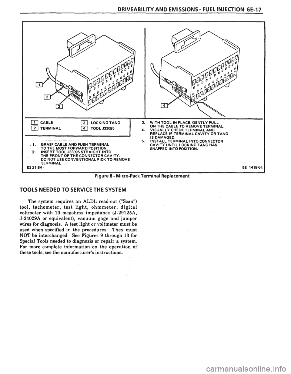
DRIVEABILITY AND EMISSIONS - FUEL INJECTION 6E-17
ON THE CABLE TO REMOVE TERMINAL. 4. VISUALLY CHECK TERMINAL AND
REPLACE IF TERMINAL CAVITY OR TANG
- -- IS DAMAGED. 5. INSTALL TERMINAL INTO CONNECTOR . 1. GRASP CABLE AND PUSH 1 ERMINAL CAVITY UNTIL LOCKING TANG HAS
TO THE MOST FORWARD POSITION.
SNAPPED INTO POSITION.
2. INSERT TOOL 533695 STRAIGHT INTO
THE FRONT OF THE CONNECTOR CAVITY.
DO NOT USE CONVENTIONAL
PICK TO REMOVE
TERMINAL.
0321 84. 5% 1418-6E
Figure 8 - Micro-Pack Terminal Replacement
TOOLS NEEDED TO SERVICE THE SYSTEM
The system requires an ALDL read-out ("Scan")
tool, tachometer, test light, ohmmeter, digital
voltmeter with 10 megohms impedance
(5-2912514,
J-34029A or equivalent), vacuum gage and jumper
wires for diagnosis. A test light or voltmeter must be
used when specified in the procedures. They must
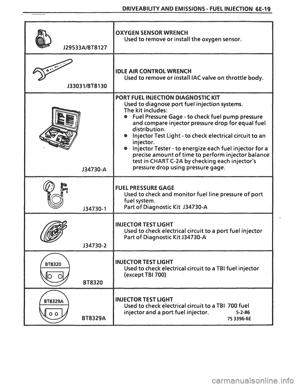
NOT be interchanged. See Figures 9 through 13 for
Special Tools needed to diagnosis or repair a system.
For more complete information on the operation of
these tools, see the manufacturer's instructions.
Page 980 of 1825
DRIVEABILITY AND EMISSIONS - FUEL INJECTION 6E-19
OXYGEN SENSOR WRENCH
Used to remove or install the oxygen sensor.
IDLE AIR CONTROL WRENCH
Used to remove or install IAC valve on throttle body.
PORT FUEL INJECTION DIAGNOSTIC KIT
Used to diagnose poPt fuel injection systems.
The kit includes:
@ Fuel Pressure Gage -to check fuel pump pressure
and compare injector pressure drop for equal fuel
distribution. lnjector Test Light -to check electrical circuit to an
injeclor.
@ Injector Tester - to energize each fuel injector for a
precise amount of time to perform injector balance
test in
CHART C-2A by checking each injector's
pressure drop using pressure gage.
FUEL PRESSURE GAGE
Used to check and monitor fuel line pressure of port
fuel system.
Part of Diagnostic Kit 134730-A
INJECTOR TEST LIGHT
Used to check electrical circuit to a port fuel injector
Pae of Diagnostic Kit 134730-A
INJECTOR TEST LIGHT
Used to check eledrical circuit to a TBI fuel injector
(except
TBI 700)
INJECTOR TEST LIGHT
Used to check electrical circuit to a TBI 700 fuel
injector and a port fuel injector.
5-2-86
75 3396-6E
Page 991 of 1825

700-R4-2 HYDRAULIC DIAGNOSIS
R - Reverse allows the vehicle to be operated in
a rearward direction.
N - Neutral allows the engine to be started and
operated without driving the vehicle. If necessary this
position may be selected if the engine must be restarted
with the vehicle moving.
D - Overdrive is used for all normal driving
conditions. It provides four gear ratios plus converter
clutch operation. Downshifts are available for safe
passing by depressing the accelerator.
D - Drive position is used for city traffic, hilly
terrain, and trailer towing. It provides three gear
ranges. Again, downshifts are available by depressing
the accelerator.
2 - Manual second is used to provide acceleration
and engine braking. This range may be selected at any
vehicle speed.
1 - Manual Lo is used to provide maximum
engine
brlking. This range may also be selected at any
vehicle speed.
DIAGNOSIS INFORMATION
ROAD TEST PROCEDURE
e Perform the road test following the sequence
given
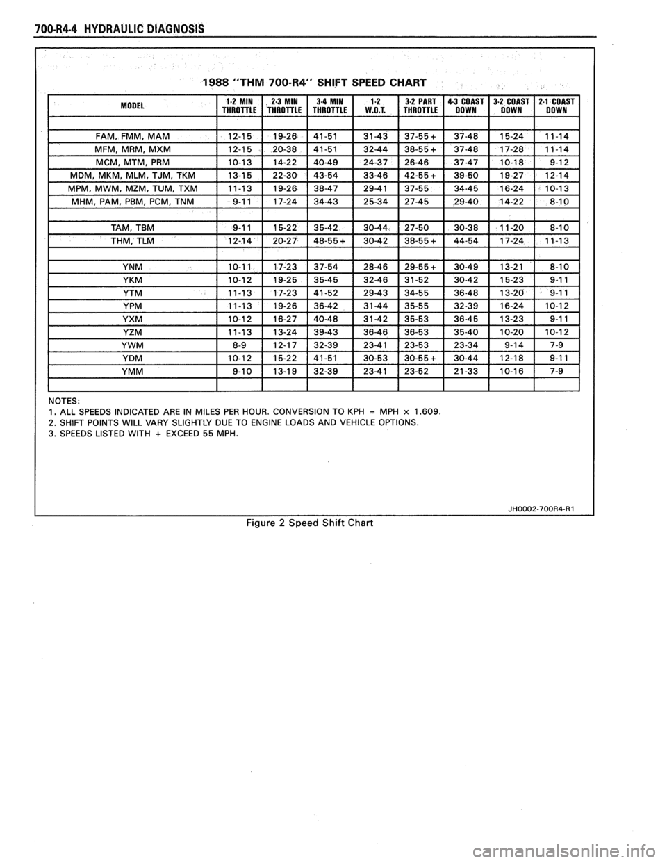
e MPH (KPH) shift points will vary with actual
throttle position and driver habits
e Compare the results of the test with speed shift
chart information. Use these results with the
diagnosis information contained in this
Automatic Transmission Hydraulic Diagnosis
Section to evaluate the transmission.
e This test should only be performed when traffic
and road conditions permit
e Observe all traffic safety regulations
Drive and Reverse Engagement Shift Check
1. Start engine
2. Depress brake pedal
3. Move gear selector:
- "Park" (P) to "Reverse" (R)
- "Reverse" (R) to "Neutral"
(N) to "Drive" (D)
Gear selections should be immediate and
not harsh.
Upshifts and Torque Converter Clutch (TCC)
Apply (Figure
2)
With gear selector in "Overdrive" (D)
1. Accelerate using a steady increasing throttle
pressure
2. Note the shift speed point gear engagements for:
- 2nd gear
- 3rd gear
- Overdrive
3. Note the speed shift point for TCC apply. This
should occur while in third gear or overdrive. If
the apply is not noticed, refer to the Preliminary
Torque Converter Clutch Diagnosis information
contained in this section of the Service Manual.
Important
The torque converter clutch will not engage if
engine coolant has not reached a minimum
operating temperature of approximately 54°C
(1 30°F).
Part Throttle Downshift
At vehicle speeds of 40-55 MPH (64-88
KPH) quickly depressed the accelerator to
a half open position and observe:
- TCC releases
- Transmission downshift to 3rd gear
immediately
Full Throttle (Detent) Downshift
At vehicle speeds of 48-55 MPH (77-88
KPH) quickly depress the accelerator to a
wide open position and observe:
- TCC releases
- Transmission downshifts to 2nd gear
immediately
Manual Downshift
1. At vehicle speeds of 40-55 MPH (64 to 88 KPH)
release the accelerator pedal while moving the
gear selector to "Third" gear (D) and observe:
- TCC release
- Transmission downshift to 3rd gear should
be immediate
- Engine should slow vehicle down
2. Move gear selector to "Overdrive" and accelerate
to 40-45 MPH (64-72 KPH). Release the
accelerator pedal while moving the gear selector
to "Second" gear (2) and observe.
- TCC release
- Downshift to second gear should be
immediate
- Engine should slow vehicle down
3. Move gear selector to "Overdrive" (D) and
accelerate to 25 MPH (40 KPH). Release the
accelerator pedal while moving the gear selector
to "First" gear (1) and observe:
- TCC release
- Transmission downshift to 1st gear should
be immediate
- Engine should slow vehicle down
Coastdown Downshift
1. With the gear selector in "Overdrive" (D)
accelerate to 4th gear with TCC applied.
2. Release the accelerator pedal and lightly apply
the brakes to observe:
- TCC release
- Shift points for downshifts.
Manual Gear Range Selection
MANUAL THIRD (D)
1. With vehicle stopped, place gear selector in
"Third" (D) and accelerate to observe:
Page 993 of 1825
700-R4.4 HYDRAULIC DIAGNOSIS
1988 "THM 700-R4" SHIFT SPEED CHART
NOTES: 1. ALL SPEEDS INDICATED ARE IN MILES PER HOUR. CONVERSION TO KPH = MPH x 1.609.
2.
SHIFT POINTS WILL VARY SLIGHTLY DUE TO ENGINE LOADS AND VEHICLE OPTIONS. 3. SPEEDS LISTED WITH + EXCEED 55 MPH.
Figure 2 Speed Shift Chart
Page 1050 of 1825
TORQUE CONVERTER CLUTCH (TCC)
DIAGNOSIS
To properly diagnose the Torque Converter
Clutch (TCC) system, perform all electrical
testing first and then the hydraulic testing. Refer
to the Torque Converter Section
6E2-C8 for
additional information.
The TCC is applied by fluid pressure which is
controlled by a solenoid located inside the Automatic
Transmission assembly. The solenoid is energized or
released by making or breaking an electrical circuit
through a combination of switches and sensors.
TCC Electrical Diagnosis
e For electrical diagnosis of TCC, refer to the
specific vehicle section in Section
8A, Electrical
Diagnosis.
e For diagnosis of emission control related
components of TCC, Refer to the specific section
of
6E, Driveability and Emissions.
e For the diagnosis of TCC Hydraulic Controls,
refer to the Procedure and Wiring Diagrams
provided in this section.
Functional Check Procedure
rn Inspect
1. Install a tachometer
2. Operate the vehicle until proper operating
temperature is reached
3. Drive vehicle at 50-55 mph (80-88 Km/h) with
light throttle (road load)
4. Maintaining throttle lightly touch the brake
pedal and check for a slight bump when the TCC
releases and a slight increase in engine RPM.
5. Release the brake, slowly accelerate and check for
a re-apply of the converter clutch and a slight
decrease in engine RPM.
Preliminary Checking Procedure
The purpose of the preliminary checking
procedure is to isolate external (electrical) problems
from internal (electrical or mechanical) ones.
Important
e Use only a scale type ohmmeter. High impedance
type ohmmeters and those with a digital readout
will not work.
e An ALCL scanner may be used to verify the
electrical circuit. Remember, a completed circuit
does not indicate that the solenoid will apply.
e Do not bench test using an automotive type
battery. Accidentally crossed wires will damage
the internal diodes of the TCC solenoid.
HYDRAULIC DIAGNOSIS 700-R4-61
External Controls
rn Inspect
e Connect voltmeter between transmission
connector and ground.
e Turn key "ON"
e If 0 or low voltage is found, refer to Sections 6E
and 8A for electrical diagnosis.
e If 12 volts are present at the connector, refer to
the TCC hydraulic diagnosis.
TORQUE CONVERTER EVALUATION
Torque Converter Stator
The Torque Converter Stator roller clutch can
have one of two different type malfunctions:
A. Stator Assembly freewheels in both
directions.
B. Stator Assembly remains locked up at all
times.
Condition A-Poor Acceleration Low Speed
The vehicle tends to have poor acceleration from
a standstill. At speeds above 30-35 mph (50-55
km/h),
the car may act normal. If poor acceleration is noted,
it should first be determined that the exhaust system
is not blocked, the engine timing is correct and the
transmission is in first
(1st) gear when starting out.
If the engine freely accelerates to high
r.p.m. in
"NEUTRAL" (N), it can be assumed that the engine
and exhaust system are normal. Checking for poor
performance in "Drive" and Reverse will help
determine if the stator is freewheeling at all times.
Condition B-Poor Acceleration High Speed
Engine r.p.m. and car speed limited or restricted
at high speeds. Performance when accelerating from a
standstill is normal. Engine may over-heat. Visual
examination of the converter may reveal a blue color
from over-heating.
If the converter has been removed, the stator
roller clutch can be checked by inserting a finger into
the splined inner race of the roller clutch and trying to
turn the race in both directions. The inner race should
turn freely clockwise, but not turn or be very difficult
to turn counterclockwise.
The Converter Should Be Replaced If:
e Leaks externally, such as at the hub weld area.
e Converter has an imbalance which cannot be
corrected. (Refer to Converter Vibration Test
Procedure).
e Converter is contaminated with engine coolant
containing antifreeze.
The Converter Should Not Be Replaced If:
e The oil has an odor, is discolored, and there is no
evidence of metal or clutch facing particles.
e The threads in one or more of the three converter
bolt holes are damaged.
- Correct with thread insert. (Refer to Section
6A).
Page 1070 of 1825
AUTOMATIC TRANSMISSION 700-R4-19
- Steel for heat damage or surface finish
damage
Reaction carrier assembly (681) for
- pinion gear damage
- excessive pinion washer wear (end play -20-.
61 mm/.008-.024 in.)
- proper pinion staking
- keystoned pinion gears (pinions must turn
free)
- damaged or worn thrust bearing
To check the captive thrust bearing in the
carrier for wear, place a bushing or an
output shaft sleeve on the bearing race (do
not contact the pinion gears) and turn it
with the palm of your hand. Any
imperfections will be felt through the
bushing.
A PINION GEAR END PLAY -
.20/.60 MM (.008/.024 IN .)
Figure 103 Pinion End Play Check
Reaction Internal Gear and Support
lnstall or Connect (Figures 106)
1. Reaction gear support to case bearing (692) onto
the case hub as shown
- Outside bearing race goes toward case hub.
- retain with petrolatum.
2. Reaction internal gear and support (684 and 685)
onto the bearing as shown
3. Reaction carrier to support thrust bearing
assembly (683) onto the support (685)
- outer bearing race goes toward the support
4. Reaction carrier (681) onto the thrust bearing
Lo and Reverse Clutch
Measure (Figure 107 and 108)
TOOLS REQUIRED
e Scale and straight edge
1. To Measure for proper selection backing plate,
stack the lo and reverse assembly on a flat surface
in the following order:
o 1 waved plate (682B)
662
CARRIER ASSEMBLY, I NPU'T - COMPLETE
690 SLEEVE, OUTPUT SHAFT
JH0090-700R4
Figure 104 Captured Bearing Check
5 fiber and 4 steal plates (682), starting with
one fiber plate and alternating with a steal
plate.
Lo and Reverse Clutch Support (679)
2. Apply an evenly distributed load to the top of the
Lo and Reverse Support Assembly (679) Light
pressure (5 lbs.) on the Lo and Reverse Support
Assembly (679) will provide the correct
dimension for measurement.
CAUTION: EXCESSIVE PRESSURE
WILL START TO FLATTEN THE
WAVE PLATE RESULTING IN AN
INACCURATE MEASUREMENT
3. Measure
the height of the clutch pack from the
work surface to the top of the Lo and Reverse
Clutch Support (Dimension D)
4. Use dimension D to select the proper thickness of
the selective spacer plate for assembly.
5. Install the proper selective spacer plate between
the wave plate and the first fiber clutch plate with
the identification side up.
6. The
overall height for dimension D with the
selective spacer plate included should be 30.515
mm
- 31.401 mm (1.20" - 1.24).
Install or Connect (Figures 107, 108, 109 and 110)
5. Lo and reverse clutch plates (682) into case lugs
- start with a steel plate and alternate with
composition.
- index with the splines of the reaction carrier
and the case as shown.
Page 1088 of 1825
AUTOMATIC TRANSMISSION 700-R4-37
600 SPRING ASM., BOOST 3-4 CLUTCH 639 HUB, OVERRUN CLUTCH
61 9 RING, OIL SEAL (TURBINE SHAFT) 641 RETAINER & RACE ASSEMBLY, SPRAG
620 RETAINER & CHECK BALL ASSEMBLY 642 FORWARD SPRAG ASSEMBLY
621 HOUSING
& SHAFT ASSEMBLY, INPUT 643 RETAINER RINGS, SPRAG ASSEMBLY
622 SEAL, "0" RING INPUT TO FORWARD HSG. 644 RACE, FORWARD CLUTCH (OUTER)
623 PISTON, 3RD & 4TH CLUTCH 645 PLATE ASSEMBLY, OVERRUN CLUTCH
624 SEAL, 3RD
& 4TH CL. (INNER & OUTER) (STEEL & COMP.)
625 RING, 3RD
& 4TH CLUTCH APPLY 646
PLATE, FORWARD CLUTCH APPLY
626 SPRING ASSEMBLY, 3RD & 4TH CLUTCH 648 PLATE, FORWARD CLUTCH (WAVED)
628 HOUSING, FORWARD CLUTCH 649
PLATE ASSEMBLY, FORWARD CLUTCH
629 SEAL, FORWARD CLUTCH (INNER
& OUTER) 650 PLATE, FORWARD CLUTCH BACKING (SEL.)
630 PISTON, FORWARD CLUTCH 651
RING, FORWARD CLUTCH BACKING PLATE
631 SEAL, OVERRUN CLUTCH (INNER & OUTER) RETAINER
632 PISTON, OVERRUN CLUTCH 652
PLATE, 3RD & 4TH CLUTCH RING RETAINER
634 SPRING ASSEMBLY, OVERRUN CLUTCH 653 PLATE, 3RD & 4TH CL. APPLY (STEPPED)
635 SNAP RING, OVERRUN CLUTCH SPRING 654 PLATE ASSEMBLY, 3RD & 4TH CLUTCH
RETAINER 655 PLATE, 3RD
& 4TH CLUTCH BACKING (SEL.) 636 SEAL, INPUT HOUSING TO OUTPUT SHAFT 656 RING, 3RD & 4TH CLUTCH BACKING
637 BEARING ASSEMBLY, INPUT SUN GEAR PLATE
RETAINER
638 SNAP RING, OVERRUN CL. HUB RETAINING
~~0129-700~4
Figure 147 Input Clutch Assembly
e Oil seal assembly for damage or wear Pump Body
Clean
e Wash and air dry all parts.
- do not wipe dry with a cloth.
Measure (Figure 159)
TOOL REQUIRED:
One inch Mircormeter
e Oil pump rotor (214) thickness
Oil pump slide (206) thickness
Important Assemble
(Figures 160, 161 and 162)
TOOL REQUIRED:
J-250 16 Seal Installer
1.
"0" ring seal (205) and oil seal ring (204) into the
groove on the back side of the slide
- retain with petrolatum.
2. Pivot
pin spring (207) and pivot pin (208) into the
pump body
3. Slide (206)
- index the notch in the slide with the pivot
pin.
- the oil seal ring must face downward into
the pump pocket.
4. Slide seal
(2 1 1) and support (2 10)
5. Vane guide ring (2 12)
Measurement of
rotor/slide must be made on 6.
Rotor
guide (213) onto the rotor
undamaged surfaces. Select similar size replacements.
- retain with petrolatum.
Lightly hone both sides of replacement rotor or
slide 7. Rotor (214)
to remove any nicks or burrs. - with guide toward the pump pocket.