1988 PONTIAC FIERO light
[x] Cancel search: lightPage 1166 of 1825
CONTENTS
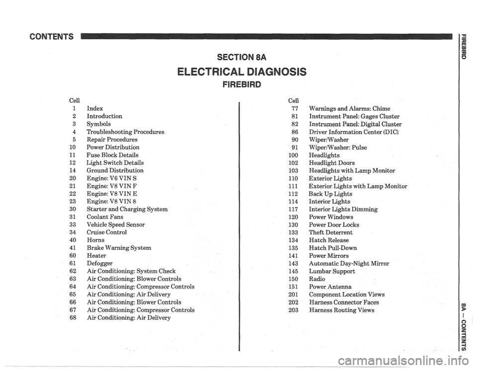
ELECTRICAL DIAGNOSIS
Cell
1
2
3
4 5
10
11
12 14
20
21
22
23
30
31
33
34
40
4
1
60
61
62
63
64
65
66
67
68
Index
Introduction
Symbols
Troubleshooting Procedures Repair Procedures
Power Distribution
Fuse Block Details
Light Switch Details
Ground Distribution
Engine:
V6 VIN S
Engine: V8 VIN
F
Engine: V8 VIN E
Engine:
V8 VIN 8
Starter and Charging System
Coolant Fans
Vehicle Speed Sensor
Cruise Control Horns
Brake Warning System
Heater
Defogger
Air Conditioning: System Check
Air Conditioning: Blower Controls
Air Conditioning: Compressor Controls
Air Conditioning: Air Delivery
Air Conditioning: Blower Controls
Air Conditioning: Compressor Controls
Air Conditioning: Air Delivery Cell
77
8
1
82
86 90
9
1
100
102
103
110
111
112
114
117
120
130
133
134
135
141
143
145
150
151
201 202
203
Warnings and Alarms: Chime
Instrument Panel: Gages Cluster
Instrument Panel:
Digital Cluster
Driver Information Center
(DIC)
WiperlWasher
WiperlWasher: Pulse
Headlights
Headlight Doors
Headlights with Lamp Monitor
Exterior Lights
Exterior Lights with Lamp Monitor
Back Up Lights
Interior Lights
Interior Lights Dimming
Power Windows
Power Door Locks
Theft Deterrent
Hatch Release
Hatch Pull-Down
Power Mirrors
Automatic Day-Night Mirror
Lumbar Support
Radio Power Antenna
Component Location Views
Harness Connector Faces
Harness Routing Views
Page 1167 of 1825
Page
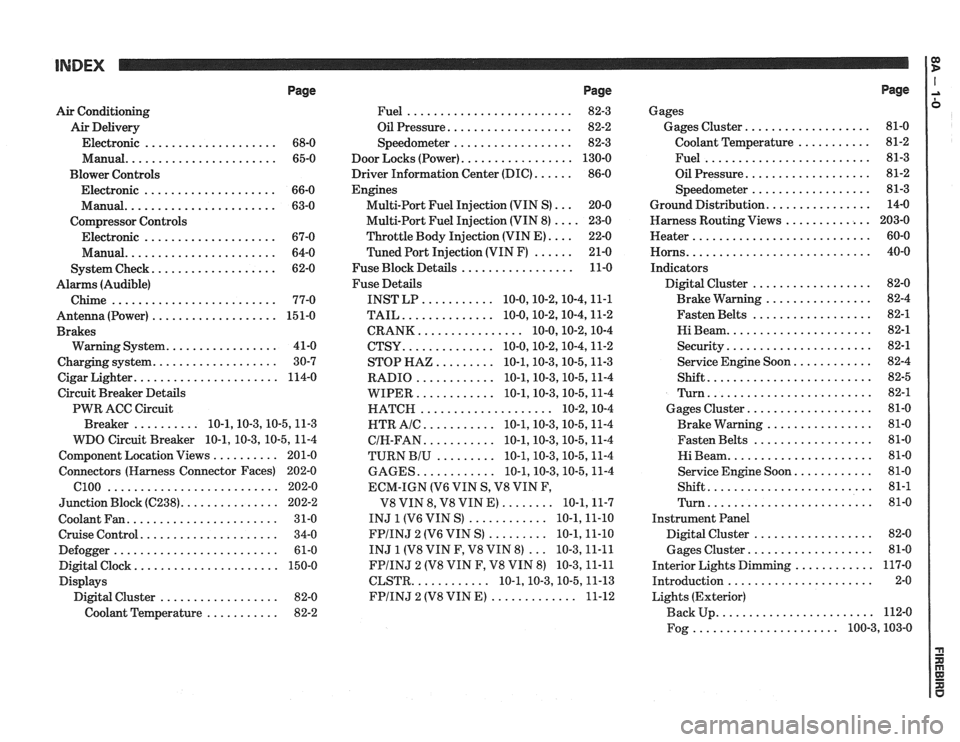
Air Conditioning
Air Delivery
Electronic
.................... 68-0
Manual
....................... 65-0
Blower Controls
Electronic
.................... 66-0
Manual
....................... 63-0
Compressor Controls Electronic
.................... 67-0
Manual
....................... 64-0
................... System Check 62-0
Alarms (Audible)
Chime
......................... 77-0
Antenna(Power) ................... 151-0
Brakes
................. Warning System 41-0
................... Charging system 30-7
...................... Cigar Lighter 114-0
Circuit Breaker Details
PWR ACC Circuit
.......... Breaker 10.1.10.3.10.5.1 1.3
WDO Circuit Breaker
10.1. 10.3. 10.5. 11-4
.......... Component Location Views 201-0
Connectors (Harness Connector Faces) 202-0
el00 .......................... 202-0
............... Junction Block ((2238) 202-2
Coolant Fan
....................... 31-0
Cruise Control
..................... 34-0
Defogger
......................... 61-0
Digital Clock
...................... 150-0
Displays Digital Cluster
.................. 82-0
Coolant Temperature
........... 82-2
Page
......................... Fuel 82-3
................... Oil Pressure 82-2
.................. Speedometer 82-3
................. Door Locks (Power) 130-0
...... Driver Information Center (DIC) 86-0
Engines
... Multi-Port Fuel Injection (VIN S) 20-0
.... Multi-Port Fuel Injection (VIN 8) 23-0
.... Throttle
Body Injection (VIN E) 22-0
...... Tuned
Port Injection (VIN F) 21-0
................. Fuse Block Details 11-0
Fuse Details
........... INST LP 10.0.10.2.10.4.1 1.1
.............. TAIL 10.0.10.2.10.4.1 1.2
................ CRANK 10.0.10.2.1 0.4
.............. CTSY 10~0.10.2.10.4.1 1.2
......... STOP HAZ 10.1.10.3.10.5.1 1.3
............ RADIO 10.1.10.3.10.5.1 1.4
............ WIPER 10.1.10.3.10.5.1 1.4
.................... HATCH 10.2.1 0.4
........... HTR AlC 10.1.10.3.10.5.1 1.4
........... CIH.FAN 10.1.10.3.10.5.1 1.4
......... TURN BIU 10.1.10.3.10.5.1 1.4
............ GAGES 10.1.10.3.10.5.1 1.4
ECM-IGN
(V6 VIN S. V8 VIN F.
........ V8 VIN 8. V8 VIN E) 10.1.1 1.7
............ INJ 1 (V6 VIN S) 10.1.1 1.10
......... FPIINJ 2 (V6 VIN S) 10.1.1 1.10
... INJ 1 (V8 VIN F. V8 VIN 8) 10.3.1 1.11
FPIINJ 2 (V8 VIN F. V8 VIN 8) 10.3.1 1.11
............ CLSTR 10.1.10.3.10.5.1 1.13
............. FPIINJ 2 (V8 VIN E) 11-12
Page
Gages
................... Gages Cluster 81-0
........... Coolant Temperature 81-2
......................... Fuel 81-3
................... Oil Pressure 81-2
.................. Speedometer 81-3
................ Ground Distribution 14-0
Harness Routing Views
............. 203-0
........................... Heater 60-0
............................ Horns 40-0
Indicators
.................. Digital Cluster 82-0
................ Brake Warning 82-4
.................. Fasten Belts 82-1
...................... Hi Beam 82-1
...................... Security 82-1
............ Service Engine Soon 82-4
......................... Shift 82-5
......................... Turn 82-1
................... Gages Cluster 81-0
................ Brake Warning 81-0
.................. Fasten Belts 81-0
...................... Hi Beam 81-0
............ Service Engine Soon 81-0
......................... Shift 81-1
......................... Turn 81-0
Instrument Panel
Digital Cluster
.................. 82-0
Gages Cluster
................... 81-0
............ Interior Lights Dimming 117-0
...................... Introduction 2-0
Lights (Exterior)
........................ Back Up 112-0
...................... Fog 100.3,10 3.0
Page 1168 of 1825
INDEX
Page
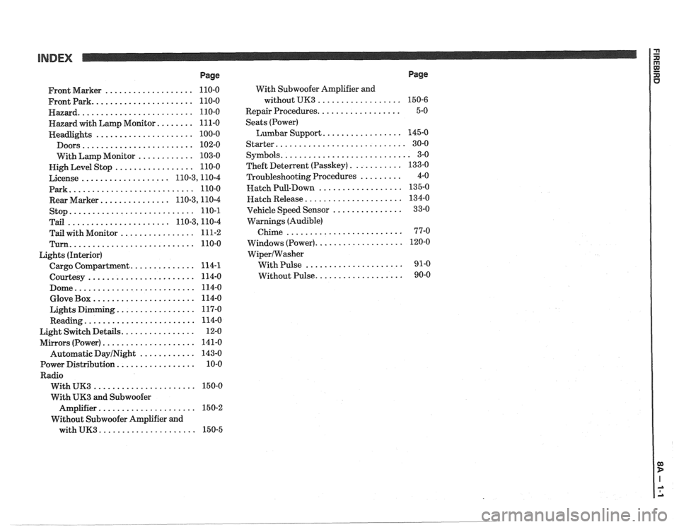
................... Front Marker 110-0
...................... Frontpark 110-0
......................... Hazard 110-0
........ Hazard with Lamp Monitor 111-0
..................... Headlights 100-0
........................ Doors 102-0
............ With Lamp Monitor 103-0
................. Nigh Level Stop 110-0
................... License 110.3,11 0.4
Park
........................... 110-0
............... Rear Marker 110.3,11 0.4
stop
........................... 110-1
...................... Tail 110.3,11 0.4
................ Tail with Monitor 111-2
Turn ........................... 110-0
Lights (Interior)
.............. Cargo Compartment 114-1
....................... Courtesy 114-0
.......................... Dome 114-0
...................... Glove Box 114-0
................. Lights Dimming 117-0
........................ Reading 114-0
................ Light Switch Details 12-0
.................... Mirrors (Power) 141-0
Automatic
DayINight ............ 143-0
................. Power Distribution 10-0
Radio
...................... With UK3 150-0
With
UK3 and Subwoofer
..................... Amplifier 15 0-2
Without Subwoofer Amplifier and
with
UK3 ..................... 150-5 With
Subwoofer Amplifier and
without UK3
..................
.................. Repair Procedures
Seats (Power)
Lumbar Support
.................
Starter ............................
........................... Symbols
........... Theft Deterlent (Passkey)
......... Troubleshooting Procedures
.................. Hatch Pull-Down
..................... Hatch Release
............... Vehicle Speed Sensor
Warnings (Audible)
Chime
.........................
................... Windows (Power)
WiperIWasher
With Pulse .....................
................... Without Pulse
Page
Page 1169 of 1825
INTRODUCTION 1:
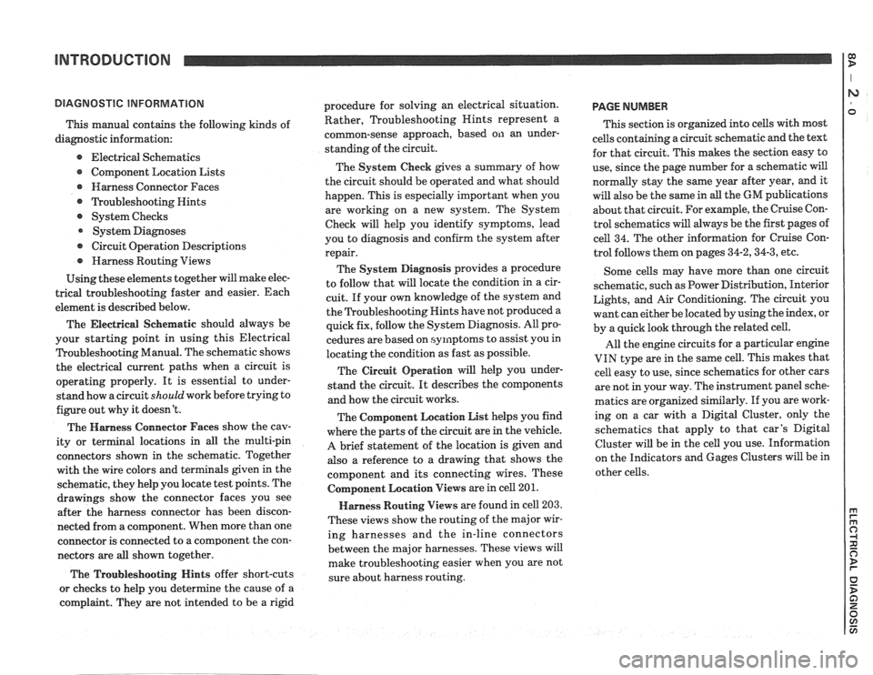
This manual contains the following kinds of
diagnostic information:
e Electrical Schematics
Component Location Lists
@ Harness Connector Faces
@ ?koubleshooting Hints
@ System Checks
System Diagnoses
@ Circuit Operation Descriptions
@ Harness Routing Views
Using these elements together will make elec-
trical troubleshooting faster and easier. Each
element is described below.
The Electrical
Seher~latic should always be
your starting point in using this Electrical
Troubleshooting Manual. The schematic shows
the electrical current paths when a circuit is
operating properly. It is essential to under-
stand how a circuit
should work before trying to
figure out why it doesn't.
The Harness Connector Faces show the cav-
ity or terminal locations in all the multi-pin
connectors shown in the schematic. Together
with the wire colors and terminals given in the
schematic, they help you locate test points. The
drawings show the connector faces you see
after the harness connector has been discon-
nected from a component. When more than one
connector is connected to a component the con-
nectors are all shown together.
The Troubleshooting Hints offer short-cuts
or checks to help you determine the cause of
a
complaint. They are not intended to be a rigid procedure
for solving an electrical situation.
Rather, Troubleshooting Nints represent a
common-sense approach, based on an under-
standing of the circuit.
The System Check gives a summary of how
the circuit should be operated and what should
happen. This is especially important when you
are working on a new system. The System
Check will help you identify symptoms, lead
you to diagnosis and confirm the system after
repair.
The System Diagnosis provides a procedure
to follow that will locate the condition in a cir-
cuit. If your own knowledge of the system and
the Troubleshooting Hints have not produced
a
quick fix, follow the System Diagnosis. All pro-
cedures are based on symptoms to assist you in
locating the condition as fast as possible.
The Circuit Operation will help you under-
stand the circuit. It describes the components
and how the circuit works.
The Component Location List helps you find
where the parts of the circuit are in the vehicle.
A brief statement of the location is given and
also a reference to a drawing that shows the
component and its connecting wires. These
Colnponent Location Views are in cell 201.
Harness Routing Views are found in cell 203.
These views show the routing of the major wir-
ing harnesses and the in-line connectors
between the major harnesses. These views will
make troubleshooting easier when you are not
sure about harness routing.
PAGE NUMBER
This section is organized into cells with most
cells containing a circuit schematic and the text
for that circuit. This makes the section easy to
use, since the page number for a schematic will
normally stay the same year after year, and it
will also be the same in
all the GM publications
about that circuit. For example, the Cruise Con-
trol schematics will always be the first pages of
cell 34. The other information for Cruise Con-
trol follows them on pages
34-2,34-3, etc.
Some cells may have more than one circuit
schematic, such as Power Distribution, Interior
Lights, and Air Conditioning. The circuit you
want can either be located by using the index, or
by a quick look through the related cell.
All the engine circuits for a particular engine
VIN type are in the same cell. This makes that
cell easy to use, since schematics for other cars
are not in your way. The instrument panel sche-
matics are organized similarly. If you are work-
ing on a car with a Digital Cluster, only the
schematics that apply to that car's Digital
Cluster will be in the cell you use. Information
on the Indicators and Gages Clusters will be in
other cells.
Page 1171 of 1825
INTRODUCTION
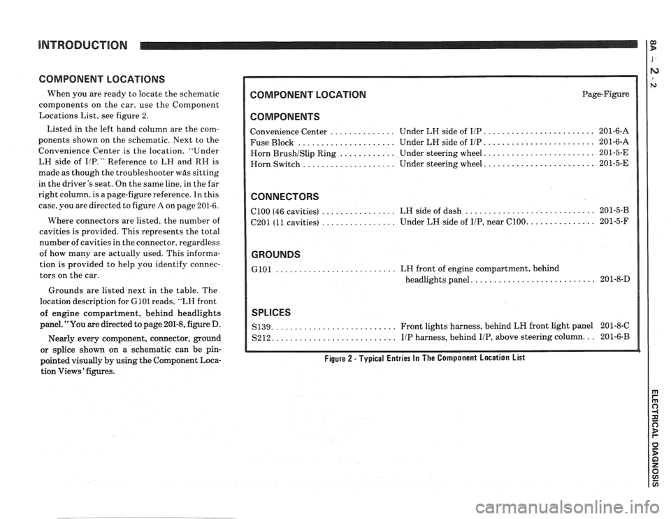
COMPONENT LOCATIONS
When you are ready to locate the schematic
components on the car, use the Component
Locations List, see figure 2.
Listed in the left hand column are the com-
ponents shown on the schematic. Next to the
Convenience Center is the location, "Under
LH side of
I/P." Reference to LH and RH is
made as though the troubleshooter
was sitting
in the driver's seat. On the same line, in the far
right column, is a page-figure reference. In this
case, you are directed to figure
A on page 201-6.
Where connectors are listed, the number of
cavities is provided. This represents the total
number of cavities in the connector, regardless
of how many are actually used. This informa-
tion is provided to help you identify connec-
tors on the car.
Grounds are listed next in the table. The
location description for
GlOl reads, "LH front
of engine compartment, behind headlights
panel. "You are directed to page 201-8, figure D.
Nearly every component, connector, ground
or splice shown on a schematic can be pin-
pointed visually by using the Component Loca-
tion Views' figures.
COMPONENT LOCATION Page-Figure
COMPONENTS
........................ Convenience Center .............. Under LH side of IIP 201-6-A
..................... ........................ Fuse Block Under LH side of IIP 201-6-A
....................... Horn BrushISlip Ring ............ Under steering wheel. 201-5-E
....................... Horn
Switch .................... Under steering wheel. 201-5-E
CONNECTORS
............................ ................ ClOO (46 cavities)
LH side of dash 201-5-B
................ .............. C201 (11 cavities) Under
LH side of IIP, near C100. 201-5-F
GROUNDS
.......................... GlOl LH front of engine compartment, behind
.......................... headlights panel. 201-8-D
SPLICES
.......................... S139. Front lights harness, behind LH front light panel 201-8-C
.......................... S212. IIP harness, behind IIP, above steering column. .. 201-6-B
Figure 2 - Typical Entries In The Component Location List
Page 1174 of 1825
INTRODUCTION
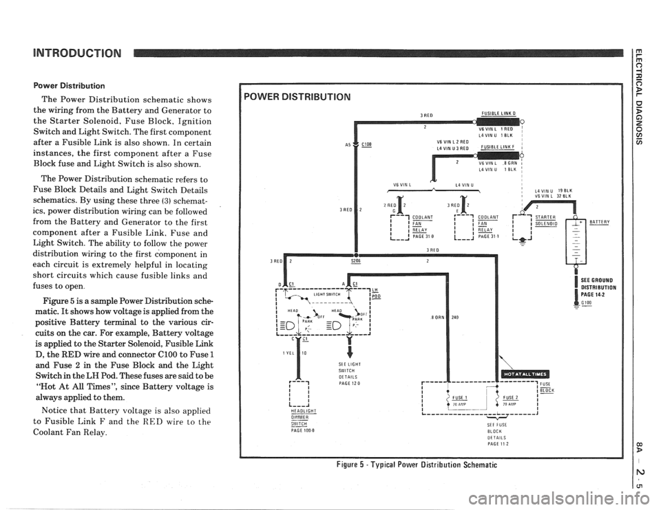
Power Distribution
The Power Distribution schematic shows
the wiring from the Battery and Generator to
the Starter Solenoid, Fuse Block, Ignition
Switch and Light Switch. The first component
after a Fusible Link is also shown. In certain
instances, the first component after a Fuse
Block fuse and Light Switch is also shown.
The Power Distribution schematic refers to
Fuse Block Details and Light Switch Details
schematics. By using these three
(3) schemat-
ics, power distribution wiring can be followed
from the Battery and Generator to the first
component after a Fusible Link. Fuse and
Light Switch. The ability to follow the power
distribution wiring to the first component in
each circuit is extremely helpful in locating
short circuits which cause fusible links and
fuses to open.
Figure
5 is a sample Power Distribution sche-
matic.
It shows how voltage is applied from the
positive Battery terminal to the various cir-
cuits on the car. For example, Battery voltage
is applied to the Starter Solenoid, Fusible Link
D, the
RED wire and connector ClOO to Fuse 1
and Fuse 2 in the Fuse Block and the Light
Switch in the
LH Pod. These fuses are said to be
"Not At All Times", since Battery voltage is
always applied to them.
Notice that Battery voltage is
also applied
to Fusible Link
F and the RED wire to the
Coolant Fan Relay.
L4VIN U 1 ELK I
i VSVIN L 32 BLK
DISTRIBUTION
SkE LIGHT
HEADLIGHT
--
PAGE 100 0 BLOCK DETAILS PAGE 11 2
Figure 5 -Typical Power Distribution Schematic
Page 1175 of 1825
INTRODUCTION
Fuse Block Details
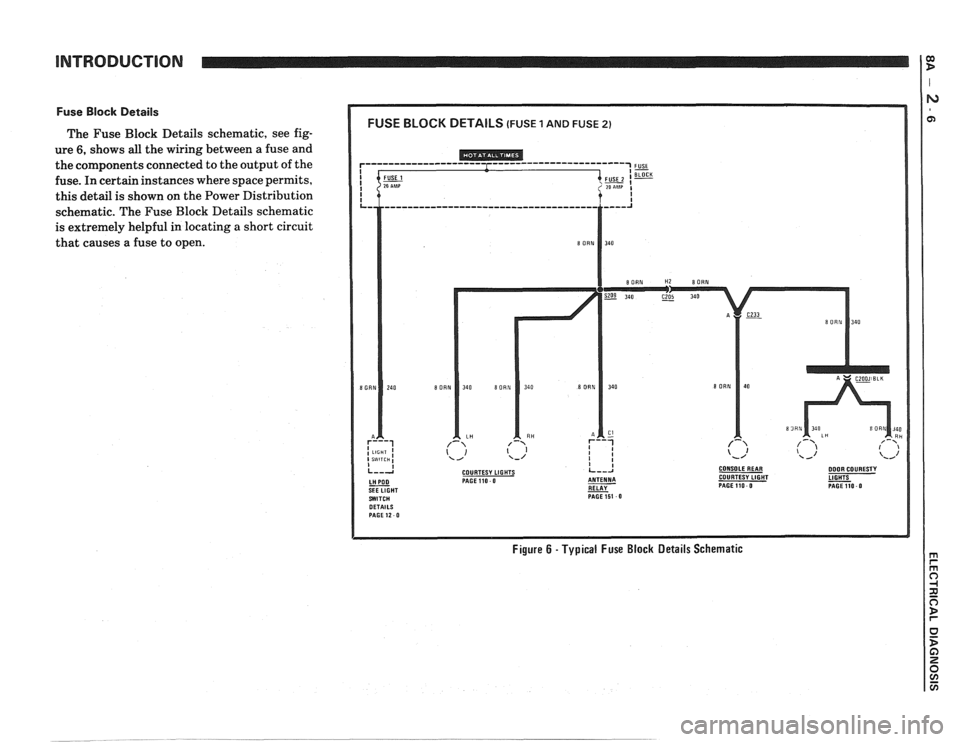
The Fuse Block Details schematic, see fig-
ure
6, shows all the wiring between a fuse and
the components connected to the output of the
fuse. In certain instances where space permits,
this detail is shown on the Power Distribution
schematic. The Fuse Block Details schematic
is extremely helpful in locating
a short circuit
that causes a fuse to open.
COURTESY LIGHTS CONSOLEREAR DOOR COURESTY PAGE110 0 COURTESY LIGHT
RELAY - PAGEllO 0 PAGE151 0
Figure 6 - Typical Fuse Block Details Schematic
Page 1176 of 1825
INTRODUCTION
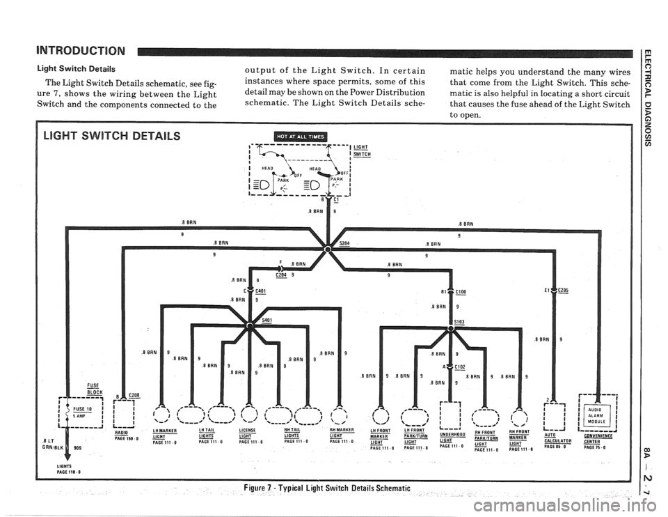
Light Switch Details output of the Light Switch. In certain matic helps you understand the many wires
The Light Switch Details schematic, see
fig- instances where space permits, some of this
that come from the Light Switch. This sche-
ure 7, shows the wiring between the Light detail
may be shown on the Power Distribution matic is also helpful in locating a short circuit
Switch and the components connected to the schematic.
The Light Switch Details
sche- that causes the fuse ahead of the Light Switch
to open.
LIGHT SWITCH DETAILS ,' '6--- ----- --- 5""l LIGHT