1988 PONTIAC FIERO light
[x] Cancel search: lightPage 1117 of 1825
7A-2 AUTOMATIC TRANSMISSION
I I
M - INDICATES TRANSMISSION
TYPE IN OPTION LIST. (SPECIFIC MODEL CODE IS FOUND ON THE I MX - DESIGNATES
11 SERVICE PARTS IDEMTIFICATIOM I 1 00 MOT REMOVE I
1G3AR47YXE5
C90 C95 DF3 D3C 033 0 GI GW9 G60 GU2 G89
JAl JA4 KO5 K22 Kg9 LV2 NA5 NB1 NKl NK3 N33 N67 GJW
T87 UJ3 U23 U35
VO8 V10 WC3 WG2 YT9 Y56 OIL 6SC 428 421 420
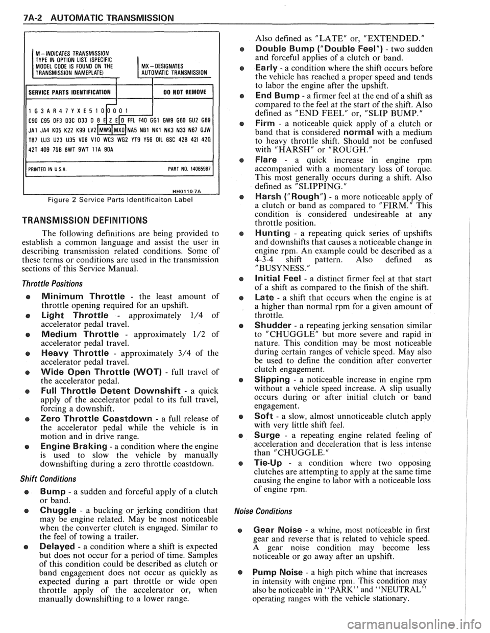
Figure 2 Service Parts ldentificaiton Label
TRANSMISSION DEFINITIONS
The following definitions are being provided to
establish a common language and assist the user in
describing transmission related conditions. Some of
these terms or conditions are used in the transmission
sections of this Service Manual.
Throttle Positions
Minimum Throttle - the least amount of
throttle opening required for an upshift.
Light Throttle - approximately 1/4 of
accelerator pedal travel.
Medium Throttle - approximately 1/2 of
accelerator pedal travel.
Heavy Throttle - approximately 3/4 of the
accelerator pedal travel.
Wide Open Throttle (WOT) - full travel of
the accelerator pedal.
Full Throttle Detent Downshift - a quick
apply of the accelerator pedal to its full travel,
forcing a downshift.
Zero Throttle Coastdown - a full release of
the accelerator pedal while the vehicle is in
motion and in drive range.
Engine Braking - a condition where the engine
is used to slow the vehicle by manually
downshifting during a zero throttle coastdown.
Shift Conditions
'a Bump - a sudden and forceful apply of a clutch
or band.
Q Chuggle - a bucking or jerking condition that
may be engine related. May be most noticeable
when the converter clutch is engaged. Similar to
the feel of towing a trailer.
e Delayed - a condition where a shift is expected
but does not occur for a period of time. Samples
of this condition could be described as clutch or
band engagement does not occur as quickly as
expected during a part throttle or wide open
throttle apply of the accelerator or, when
manually downshifting to a lower range. Also
defined as "LATE" or, "EXTENDED."
Double Bump ("Double Feel") - two sudden
and forceful applies of a clutch or band.
Early - a condition where the shift occurs before
the vehicle has reached a proper speed and tends
to labor the engine after the upshift.
End Bump - a firmer feel at the end of a shift as
compared to the feel at the start of the shift. Also
defined as "END FEEL" or, "SLIP BUMP."
Firm - a noticeable quick apply of a clutch or
band that is considered
normal with a medium
to heavy throttle shift. Should not be confused
with "HARSH" or "ROUGH."
Flare - a quick increase in engine rpm
accompanied with a momentary loss of torque.
This most generally occurs during a shift. Also
defined as "SLIPPING.
"
Harsh ("Rough") - a more noticeable apply of
a clutch or band as compared to "FIRM." This
condition is considered undesireable at any
throttle position.
Hunting - a repeating quick series of upshifts
and downshifts that causes a noticeable change in
engine rpm. An example could be described as a
4-3-4 shift pattern. Also defined as
"BUSYNESS.
"
Initial Feel - a distinct firmer feel at that start
of a shift as compared to the finish of the shift.
Late - a shift that occurs when the engine is at
a higher than normal rpm for a given amount of
throttle.
Shudder - a repeating jerking sensation similar
to "CHUGGLE" but more severe and rapid in
nature. This condition may be most noticeable
during certain ranges of vehicle speed. May also
be used to define the condition after converter
clutch engagement.
Slipping - a noticeable increase in engine rpm
without a vehicle speed increase.
A slip usually
occurs during or after initial clutch or band
engagement.
Soft - a slow, almost unnoticeable clutch apply
with very little shift feel.
Surge - a repeating engine related feeling of
acceleration and deceleration that is less intense
than "CHUGGLE.
"
Tie-Up - a condition where two opposing
clutches are attempting to apply at the same time
causing the engine to labor with a noticeable loss
of engine rpm.
,e Conditions
Gear Noise - a whine, most noticeable in first
gear and reverse that is related to vehicle speed.
A gear noise condition may become less
noticeable or go away after an upshift.
Pump Noise - a high pitch whine that increases
in intensity with engine
rpm. This condition may
also be noticeable in
"PARK" and "NEUTRAL"
operating ranges with the vehicle stationary.
Page 1121 of 1825
7A1-2 AUTOMATIC TRANSMISSION ON-VEHICLE SERVICE
Pitting
FLEXPLATE/TORQUE CONVERTER VIBRATION
TEST PROCEDURE
1. Start engine
2. With engine at idle speed and the transmission in
"Park"
(P) or "Neutral" (N), observe vibration.
3. Shut off engine.
Remove or Disconnect
e Flexplate cover attaching bolts
s Flexplate to torque converter attaching
bolts
e Rotate torque converter 120 (1/3 turn)
Install
or Connect
e Flexplate to torque converter attaching
bolts
- Torque bolts to 47 N.m (35 Ibs. ft.)
s Flexplate cover bolts
- Torque bolts to 6 N-m (53 lbs. in.)
4. Start engine and check for vibration. Repeat this
procedure un
ti1 the best possible balance is
obtained.
NOTICE: Some engine/transmission
combinations cannot be balanced in this manner
due to limited clearances between the torque
converter bolts and engine. Be sure bolts do not
bottom out in lug nuts or the torque converter
cover could be dented and cause internal damage.
FLUID LEAK DIAGNOSIS
The cause of most external leaks can generally be
located and repaired with the transmission in the car.
METHODS FOR LOCATING LEAKS
General Method
s Verify that the leak is transmission fluid.
a Thoroughly clean the suspected leak area.
s Operate the car for about 15 miles or until normal
operating temperatures are reached.
e Park the car over clean paper or cardboard.
s Shut off engine and look for fluid spots on paper.
a Make necessary repairs.
Powder Method
e Thoroughly clean the suspected leak area with
solvent.
a Apply an aerosol type powder (foot powder) to
the suspected leak area.
s Operate the car for about 15 miles or until normal
operating temperatues are reached.
s Shut off engine.
e Inspect suspected leak area and trace the leak
path through the powder to find the source.
a Make necessary repairs.
Dye And Black Light Method
A fluid dye and black light kit is available from
various tool manufacturers.
s Follow the manufacturer's recommendations for
the amount of dye to be used.
a Detect the leak with the black light.
e Correct cause of leak.
REPAIRING THE LEAK
Once the leak has been pinpointed and traced
back to its source, the cause of the leak must be
determined in order for it to be repaired properly. If a
gasket is replaced, but the sealing flange is bent, the
new gasket will not repair the leak. The bent flange
must be repaired also. Before attempting to repair a
leak, check to be sure that the following conditions are
correct as they may cause a leak.
Gaskets
s Fluid level/pressure is too high.
e Plugged vent or drain-back holes.
s Improperly torqued fasteners or dirty/damaged
threads.
a Warped flanges or sealing surface.
e Scratches, burrs or other damage to the sealing
surface.
e Damaged or worn gasket.
e Cracking or porosity of the component.
s Improper sealant used (where applicable).
Seals
e Fluid level/pressure is too high.
a Plugged vent or drain-back holes.
s Damaged seal bore (scratched, burred or nicked).
e Damaged or worn seal.
e Improper installation.
a Cracks in component.
e Manual or output shaft surface scratched, nicked
or damaged.
a Loose or worn bearing causing excess seal wear.
Possible Points of Oil Leak
I. Transmission/Transmission oil pan :
Attaching bolts not correctly torqued
s Improperly installed or damaged gasket
s Oil pan or mounting face not flat
2, Case Leak :
@ Filler pipe "multi-lip seal" damaged or
missing
a Filler pipe bracket mislocated
s T.V. cable "multi-lip" seal missing,
damaged or improperly installed
a Governor cover or "0" ring damaged or
missing
@ Speedometer driven gear/speed sensor seal
damaged
e Manual shaft seal damaged
s Oil cooler connector fittings loose or
damaged
Page 1126 of 1825
AUTOMATIC TRANSMISSION ON-VEHICLE SERVICE 7A1-7
7. Place
gear selector into "DRIVE". Oil Pressure
should be equal or not more than 10 psi
(34 kPa)
higher than in "PARK".
8. Increase engine speed to 1400 RPM. If oil
pressure does not increase, adjust
T.V. cable.
Refer to T.V. Cable Adjustment.
Remove or Disconnect (Figs. 5 thru 7)
1. Air cleaner.
2. T.V. cable terminal from throttle lever.
3. Cable housing from bracket while compressing
locking tangs.
4. Routing clips or straps.
5. Raise
car, see Section OA.
6. Bolt securing T.V. cable to transmission.
o Pull up on cable cover at transmission until
cable is visible.
7. Cable from transmission link.
8. Cable seal.
Install or Connect
1. New seal into transmission case hole.
2. Transmission end of cable to T.V. link and secure
to transmission case with bolt and washer
assembly. Torque to 10
Nam (7 Ib. ft.).
3. Cable routing clips or straps.
4. Lower car.
5. Pass cable through engine bracket and engage
locking tangs of cable on bracket.
6. Avoid damaging or kinking wire cable.
7. Cable terminal to throttle lever.
Inspect
o Pull on upper end of cable. It should travel
a short distance with light resistance caused
by the small return spring on the
T.V. lever.
When releasing the upper end of the T.V.
cable, it should return to the zero T.V.
position.
Adjust
o T.V. cable. Refer to Figs. 5 thru 7.
CHANGING FLUID AND FILTER
Remove or Disconnect
1. Raise the car and support properly, see Section
OA.
2. Place drain pan under transmission oil pan.
3. Oil pan bolts from the front and sides only.
4. Loosen rear oil pan bolts approximately 4 turns.
NOTICE: Do not damage the transmission case
or oil pan sealing surfaces.
5. Lightly tap oil pan with rubber mallet or pry to
allow fluid to drain.
- Inspect fluid color
- Refer to chart in Section 7A
6. Remaining oil pan bolts, oil pan and gasket. 7. Oil filter
and o-ring
- O-ring may be stuck in the case
e Transmission case and oil pan gasket
surfaces with solvent and air dry.
- All traces of old gasket material must
be removed
Install or Connect
o Coat o-ring seal with a small amount of
petrolatum
o New o-ring onto filter
e New filter into case
a Oil pan and new gasket
e Oil pan bolts 20 N.m (15 lbs. ft.)
8. Lower car.
9. Fill transmission to proper level with
DEXRONO I1 fluid or equivalent, see Section
7A.
10. Check "Cold"
fluid level reading for initial till.
Do not overfill.
11. Follow
the "Transmission Fluid Level Checking
Procedure" in Section 7A of this Service Manual.
12. Check
oil pan gasket for leaks.
700-R4 SERVICEABLE COMPONENTS
The following parts can be serviced with the
transmission in the vehicle:
o Throttle valve control cable and/or sleeve heal
Fill tube and/or seal
o Governor assembly
a Speedometer drive and/or driven gear
e Servo assembly
a Valve body assembly, spacer plate, gaskets,
throttle lever and bracket assembly, auxiliary
valve body, TCC solenoid, switch and
wir-iug.
a Converter to flexplate bolts.
a Oil pan and/or gasket, strainer assembly and "0"
ring.
e Pressure Regular Valve.
o Rear Oil Seal.
SERVO ASSEMBLY
Remove or Disconnect (Fig. 8)
Tool Required:
J 29714-A
1. Raise car and suitably support, see Section OA.
2. Torque Arm,
see Section
3D.
3. Propeller Shaft, see Section 4A.
4. Exhaust hanger.
5. Support transmission.
6. Crossmember and transmission moulll.
7. Two
transmission oil pan bolts below servo cover.
8. Install J 29714-A on oil pan and reinstall oil pan
bolts.
9. Depress servo cover
and remove retaining ring.
10. J 29714-A.
Page 1132 of 1825
AUTOMATIC TRANSMISSION ON-VEHICLE SERVICE 7A1-13
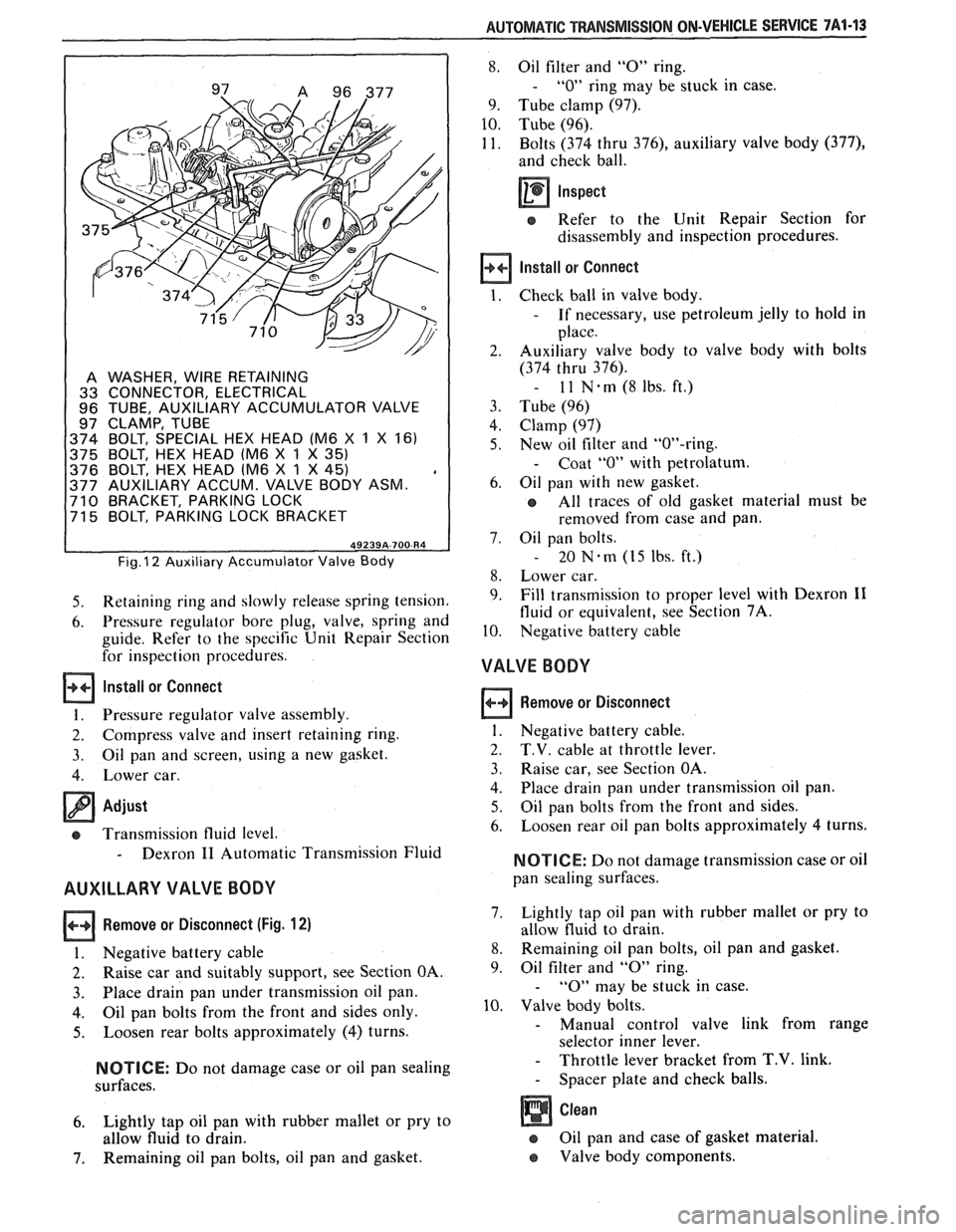
A WASHER, WIRE RETAINING
33 CONNECTOR, ELECTRICAL
96 TUBE, AUXILIARY ACCUMULATOR VALVE
97 CLAMP, TUBE
374 BOLT, SPECIAL HEX HEAD (M6
X 1 X 161
375 BOLT, HEX HEAD lM6
X 1 X 35)
376 BOLT, HEX HEAD lM6 X 1 X 45) , 377 AUXILIARY ACCUM. VALVE BODY ASM. 710 BRACKET, PARKING LOCK
71 5 BOLT, PARKING LOCK BRACKET
Fig. I2 Auxiliary Accumulator Valve Body
5. Retaining ring and slowly release spring tension.
6. Pressure regulator bore plug, valve, spring and
guide. Refer to the specific Unit Repair Section
for inspection procedures.
Install or Connect
1. Pressure regulator valve assembly.
2. Compress valve and insert retaining ring.
3. Oil pan
and screen, using a new gasket.
4. Lower car.
Adjust
cs Transmission fluid level.
- Dexron I1 Automatic Transmission Fluid
AUXILLARY VALVE BODY
Remove or Disconnect (Fig. 12)
I. Negative battery cable
2. Raise car and suitably support, see Section OA.
3. Place drain
pan under transmission oil pan.
4. Oil pan bolts from the front and sides only.
5. Loosen rear bolts approximately (4) turns.
NOTICE: Do not damage case or oil pan sealing
surfaces.
6. Lightly tap oil pan with rubber mallet or pry to
allow fluid to drain.
7. Remaining oil pan bolts, oil pan and gasket.
8. Oil filter and "0" ring.
- "0" ring may be stuck in case.
9. Tube clamp (97).
10. Tube (96).
11. Bolts (374 thru
376), auxiliary valve body (377),
and check ball.
Inspect
e Refer to the Unit Repair Section for
disassembly and inspection procedures.
Install or Connect
Check ball in valve body.
- If necessary, use petroleum jelly to hold in
place.
Auxiliary valve body to valve body with bolts
(374 thru 376).
- 11 N-rn(8lbs.ft.)
Tube (96)
Clamp (97)
New oil filter and "OW-ring.
- Coat "0" with petrolatum.
Oil pan with new gasket.
All traces of old gasket material must be
removed from case and pan.
Oil pan bolts.
- 20 Nem (15 Ibs. ft.)
Lower car.
Fill transmission to proper level with Dexron
I1
fluid or equivalent, see Section 7A.
Negative battery cable
VALVE BODY
Remove or Disconnect
1. Negative battery cable.
2. T.V. cable at throttle lever.
3. Raise car, see Section OA.
4. Place
drain pan under transmission oil pan.
5. Oil pan bolts from the front and sides.
6. Loosen
rear oil pan bolts approximately 4 turns.
NOTICE: Do not damage transmission case or oil
pan sealing surfaces.
7. Lightly
tap oil pan with rubber mallet or pry to
allow fluid to drain.
8. Remaining oil pan bolts, oil pan and gasket.
9. Oil
filter and
"0" ring.
- "0" may be stuck in case.
10. Valve body bolts.
- Manual control valve link from range
selector inner lever.
- Throttle lever bracket from T.V. link.
- Spacer plate and check balls.
Oil pan and case of gasket material.
e Valve body components.
Page 1153 of 1825
78-16 BSPEED 77MM TMNSMISSION
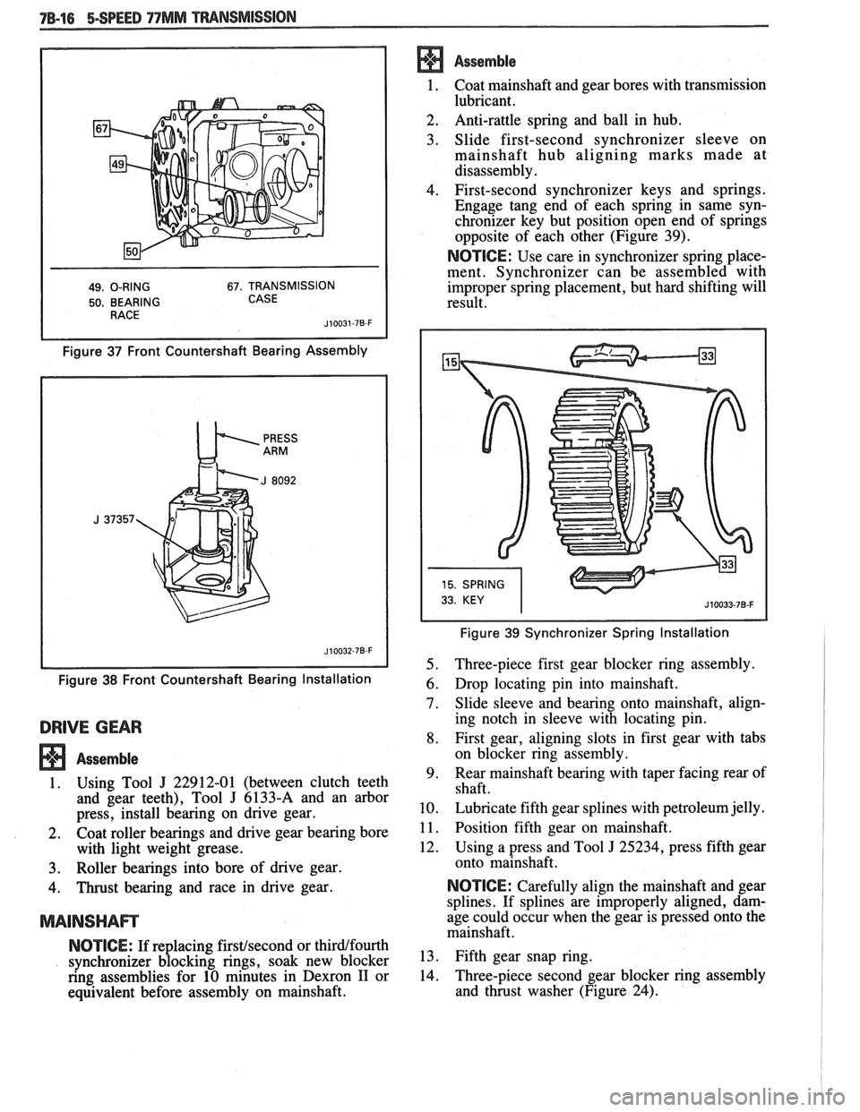
49. O-RING 67. TRANSMISSION
50. BEARING CASE
Figure 37 Front Countershaft Bearing Assembly
Figure
38 Front Countershaft Bearing Installation
DRIVE GEAR
Assemble
1. Using Tool J 22912-01 (between clutch teeth
and gear teeth), Tool
J 6133-A and an arbor
press, install bearing on drive gear.
2. Coat roller bearings and drive gear bearing bore
with light weight grease.
3. Roller bearings into bore of drive gear.
4. Thrust bearing and race in drive gear.
MAINSHAm
NOTICE: If replacing firstfsecond or thirdlfourth
synchronizer blocking rings, soak new blocker
ring assemblies for 10 minutes in Dexron
I1 or
equivalent before assembly on mainshaft.
Assemble
1. Coat mainshaft and
gear bores with transmission
lubricant.
2. Anti-rattle
spring and ball in hub.
3. Slide first-second synchronizer sleeve on
mainshaft hub aligning marks made at
disassembly.
4. First-second synchronizer keys and springs.
Engage tang end of each spring in same syn-
chronizer key but position open end of springs
opposite of each other (Figure 39).
NOTICE: Use care in synchronizer spring place-
ment. Synchronizer can be assembled with
improper spring placement, but hard shifting will
result.
Figure 39 Synchronizer Spring Installation
5. Three-piece first gear blocker ring assembly.
6. Drop locating pin into mainshaft.
7. Slide sleeve and bearing onto mainshaft, align-
ing notch in sleeve with locating pin.
8. First gear, aligning slots in first gear with tabs
on blocker ring assembly.
9. Rear
mainshaft bearing with taper facing rear of
shaft.
10. Lubricate fifth gear splines with petroleum jelly.
1 1. Position fifth gear on mainshaft.
12. Using a press and Tool
J 25234, press fifth gear
onto mainshaft.
NOTICE: Carefully align the mainshaft and gear
splines. If splines are improperly aligned, dam-
age could occur when the gear is pressed onto the
mainshaft.
13. Fifth gear snap ring.
14. Three-piece
second gear blocker ring assembly
and thrust washer (Figure 24).
Page 1159 of 1825
7C-2 CLUTCH
PRELIMINARY CHECKS
Before attempting to repair the clutch,
transmission or related hydraulic components for any
reason other than
an obvious failure, the problem and
probable cause should be identified.
A large percentage
of clutch and manual transmission
problenls are
manifested by shifting difficulties such as high shift
effort, gear clash and grinding or transmission
blockout. When any of these problems occur, a careful
analysis of these difficulties should be accomplished
and the following checks and adjustments performed
in the presented sequence before removing the clutch
or transmission for repairs.
Before
removal of the clutch hydraulic system,
verify the malfunction by renloving the clutch housing
dust shield and
measure the travel of the clutch slave
cylinder push rod. With clutch pedal pushed fully to
the floor, the
slave cylinder push rod should extend
14.53mm (0.57 inch) minimum against the clutch
release lever. Do
not replace the hydraulic system if
push rod travel exceeds this distance.
If slave cylinder does not meet the travel require-
ments, check the reservoir fluid level. The slave cylinder
must be in place when checking the fluid level. The proper
level is indicated by a step on the reservoir. Fill to the
specified level with
GM Delco Supreme No. 11 Brake
Fluid or an equivalent fluid that meets DOT
3 specifica-
tions. Do not overfill. The upper portion of the reservoir
must accept fluid that is displaced from the slave cylinder
as the clutch wears.
NOTICE: Carefully clean the top and sides of the
reservoir before opening to prevent contamination of
the system with dirt, water or other foreign material.
Remove the reservoir diaphragm before adding fluid.
Carefully replace the diaphragm, cover gasket and
cover after filling.
If the reservoir requires any fluid, check the
hydraulic system components for leakage. Remove the
rubber boots from the cylinder and check for leakage
past the pistons. A slight wetting of the surfaces is
acceptable. Replace the system, if excessive leakage is
evident.
BLEEDING CLUTCH SYSTEM
allowed to fall so low that air has been drawn into the
master cylinder.
NOTICE: Never, under any circumstances, use
fluid which has been bled from a system to fill the
reservoir as it may be aerated, have too much
moisture content and possibly be contaminated.
Clean dirt and grease from the cap to ensure no
foreign substances enter the system.
Remove cap and diaphragm and
fill reservoir to
the top with approved brake fluid only. (Brake
fluid must be certified to DOT 3 specifications).
Fully loosen bleed screw which is in the slave
cylinder body next to the inlet connection.
Fluid will now begin to move from the master
cylinder down the tube to the slave. It is
important that for efficient gravity
fill, the
reservoir must be kept full at all times.
It will be noticeable at this point that bubbles will
appear at the bleed screw outlet. This means that
air is being expelled. When the slave is full, a
steady stream of fluid will come from the slave
outlet. At this point tighten bleed screw to a
torque of 2
N .m.
Assemble diaphragm and cap to the reservoir,
fluid in reservoir should be level with step.
Exert a light load (approximately 20 lbs.) to the
slave cylinder piston by pushing release lever
towards the cylinder and loosen bleed screw.
Maintain a constant light load, fluid and any air
that is left will be expelled through the bleed port.
Tighten bleed screw when a steady flow of fluid
and no air is being expelled.
Renew fluid level in reservoir, assemble
diaphragm and cap. If necessary, repeat Steps
7
and 8.
Exert light load to release lever as in Step 7 (do
not open bleed screw), piston in slave will move
slowly down bore. Repeat 2-3 times, fluid
n~oven~ent will force any air left in the system into
the reservoir.
The hydraulic system should now be fully bled
and should release the clutch. Check vehicle by
starting, pushing clutch pedal to the floor and
selecting reverse gear. There should be no grating
of gears, if there is, the hydraulic system could
still contain air. If this is the case, repeat bleed
The process of removing air from the
line and procedure.
cylinders is known as "bleeding" and is necessary Check push rod travel at the
slave cylinder to insure
whenever the level of fluid in the reservoir has been the minimum travel
of
14.53mm (0.57 inch) for V-8
and 1 lrnm (0.43 inch) for V-6.
Page 1161 of 1825
7C.4 CLUTCH
CLUTCH DIAGNOSIS
CONDITION PROBABLE CAUSE CORRECTION
Fails to Release
(Pedal pressed to
floor shift lever a. Faulty pilot bearing. a. Replace bearing.
does not move freely b.
Faulty driven disc. b.
Replace disc.
in and out of
re- c. Fork off ball stud. c.
Install properly and*
verse gear) lubricate
fingers at
re-
lease bearing and ball stud.
d. Clutch disc hub
bind- d. Repair or replace
ing on clutch gear clutch
gear and/or disc.
spline.
e. Clutch disc warped e.
Replace disc (run-out
or bent. should
not exceed
.020").
* Very lightly lubricate
fingers.
a. Oil soaked driven a. Install new disc and
disc. correct
leak at its source.
b. Worn facing or
fac- b. Replace disc.
ing torn from disc.
c. Warped pressure c. Replace pressure plate
plate or flywheel. or flywheel.
d. Weak diaphragm
d. Replace pressure plate
spring. e. Driven plate not e. Make
30 to 40 normal
seated in. starts. CAUTION:
Do
not overheat.
f. Driven plate over- f. Allow to cool.
Slipping
Page 1163 of 1825
7C-6 CLUTCH
6. Clutch master cylinder push rod to clutch pedal.
7. Install brake switch.
8. Install hush panel.
9. Install steering column trim cover.
10. Install clutch reservoir to bracket.
1 1. Hoist vehicle.
12. Pilot slave cylinder into clutch fork.
NOTICE: With a new system, the slave cylinder
contains a shipping strap that pre-positions the
push rod for installation, and also provides a
bearing insert.
Follojving installation of the slave
cylinder, the first actuation of the clutch pedal will
break the shipping strap and give
normal system
operation.
13. Install slave cylinder and heat shield to bell
housing.
14.
Lojver vehicle.
15. Connect negative battery cable.
CLUTCH ASSEMBLY
Removal
1. Remove the transmission as outlined in
transmission section.
2. Remove the slave cylinder heat shield and slave
cylinder
from flywheel housing.
3. Reniove the flywheel housing.
4. Slide clutch fork from ball stud and remove fork
from dust boot. Ball stud is threaded into clutch
housing and is easily replaced, if necessary.
5. Install Tool 5-33169 to support the clutch
assen~bly during removal. Look for mark or white
painted letter on clutch cover and
"X" mark on
flywheel. If
"Xu or letter is not evident, mark
flywheel and clutch cover for indexing purposes
during installation.
6. Loosen clutch-to-flywheel attaching bolts evenly
1 turn at a time until spring pressure is released.
7. Remove clutch and pressure plate assembly.
lnspection
Inspect the flywheel for cracks, heat checking or
other defects. Replace or repair as required.
Installation
Pressure plate and flywheel face, (They should be
free of oil, grease, metal deposits or burned spots.)
Installation
1. Position clutch disc and pressure plate in relative
installed position and support them with
alignment Tool J-33169 or a drive gear.
The driven disc is installed with the damper
springs to the transmission. The flywheel side is
marked.
2. Turn clutch assembly until "X" mark or white
painted letter on cover lines up with
"X" mark on flywheel,
then align cover bolt holes to nearest
flywheel holes.
3. Install a bolt in every hole and tighten down
evenly and gradually until tight to avoid possible
clutch distortion. (Cover loads are as high as
1- 1/4 tons).
4. Remove the pilot tool.
5. Unhook clutch fork and lubricate ball socket and
fork fingers at release bearing end with a high
melting point grease such as graphite and
reinstall fork on ball stud.
6. Lubricate recess on inside of release bearing
collar and the clutch fork groove with light coat
of graphite grease. Refer to Figure 7C-6.
7. Install the clutch fork and dust boot into clutch
housing and install release bearing to fork, then
install flywheel housing.
8. Install the transmission as outlined in
transmission section.
9. Install the clutch slave cylinder and bracket.
CLUTCH PEDAL
Removal
Disconnect the negative cable at battery.
Remove the steering column trim cover.
Remove the hush panel from under dash.
If equipped, disconnect cruise control switch at
clutch pedal.
Disconnect the neutral start switch at clutch
pedal.
Renlove the turn signal and hazard flasher
mounting bracket attaching screws.
Disconnect the clutch master cylinder push rod
from pedal.
Remove the nut from clutch pedal pivot bolt. Pull
bolt out far enough for pedal removal.
Inspection
Clean and inspect all components and replace as
necessary. Do not clean bushings with a cleaning
solvent, simply wipe with a clean cloth.
Relubricate all bushings and moving parts.
Installation
1. Reverse the removal procedure.
PILOT BEARING (FIGURE 7C-7)
Replacement
The clutch pilot bearing is an oil impregnated type
bearing pressed into the crankshaft. This bearing requires
attention when the clutch is removed from the vehicle, at
which time it should be cleaned and inspected for exces-
sive wear or damage and should be replaced if necessary.
To remove, install Tool
J 23907 and remove bearing
from crankshaft, as shown in Figure
7C-7. In replacing
this bearing, use Tool
J 1522. Place bearing on pilot of
tool with radius in bore of bearing next to shoulder on tool
and drive into crankshaft. Lubricate with several drops of
machine oil.