1988 PONTIAC FIERO light
[x] Cancel search: lightPage 960 of 1825
INDEX
SECTION
PAGE
MEM -Cal
General Description ................. C1-I
Diagnosis ......................... C1-4
A-60
Service
........................... C1-6
Functional Check
................... C1-7
Minimum
Idle Speed Adjustment ......... C2-12
Misses ............................. 8-5
Negative Backpressure Valve ............ C7-2
No ALDL Data
....................... A- 12
No "Service Engine Soon" Light
.......... A-10
.................... Oil Pressure Switch C2-16
Oxygen Sensor
General Description
.................. C1-3
......................... Diagnosis C1-5
A.24.54. 56
........................... Service C1-8
Park Neutral Switch
General Description
................. C1-3
Diagnosis
.......................... C1-10
C1-5
Service
........................... C1-9
Poor Fuel Economy
.................... B.6.
C5-4
Poor Performance
.................... C5-4
Positive Crankcase Ventilation (PCV)
General Description. Diagnosis
......... C13-1
Service
............................ C13-2
Pressure Regulator
.................... C2-4
........................ Quad Drivers C 1-4
..................... Reference Signal C1-5
.......................... Rough Idle B-6
RunMode .......................... C2-2
RunOn ............................. B-6
SECTION PAGE
................... Sensor Information C1-2-9
"Service Engine Soon" Light On Steady .... A- 12
................... Setting Timing ... . C4-2
.......................... Shift Light C8-6
Sluggish
............................ B-4
......................... Spark Knock B-4
........................ Speed Sensor C8-2
.................. Speedo Buffer Sensor C8-4
Spongy
............................. B-4
............................ Stalling B-6
........................ Starting Mode C2-2
........................... Stumble B-3
Surges
............................. B-3
.................. System Over Voltage A-60
Throttle Body Unit
................. General Description C2-3
........................... Service C2-11
Throttle Position Sensor
................. General Description C1-3
......................... Diagnosis C1-5
A-30
....................... Adjustments C2-12
........................... Service C1-8
Transmission Converter Clutch TCC System
.................. General Description C8-1
......................... Diagnosis C8.2. 4
U
........................ Unstable Idle B-6
V
...................... Vapor Canister C3-1
Vehicle Speed Sensor
.................. General Description C1-3
.......................... Diagnosis C1-5
A-36
Vehicle Anti-Theft System (VATS)
................. General Description A-58
......................... Diagnosis A-59
W
...................... Wiring Diagrams A-3
................... Won't Flash Code 12 A-
12
Sag
.................+............. B-3
......................... "Scan" Data A-8
Page 962 of 1825
DRIVEABILITY AND EMISSIONS . FUEL INJECIION 6E-1
DRBVEABILIW AND EMISSIONS
CONEENTS
General Information . Section 6E
Driveability and Emissions . Fuel Injected (TBI) . Section 6EZ
Driveability and Emissions . Fuel injected (PORT) . Section 6E3
..................... DRIVEABILITY 6E-1
........................ EMISSIONS 6E-1
MAINTENANCE SCHEDULE ............ 6E-1
VEHICLE EMISSIONS CONTROL
............. INFORMATION UBEL 6E-3
.................... INTRODUCTION 6E-3
.......... Electronic Engine Control 6E-3
What This Section Contains .......*. 6E-3
............. Blocking Drive Wheels 6E-3
.............. Cold Oxygen Sensor 6E-3
VISUAUPHYSICAL UNDERWOOD
..................... INSPECTION 6E-3
BASIC KNOWLEDGE REQUIRED ........ 6E-3
.............. Basic Electric Circuits 6E-3
Use of Circuit Testing Tools ......... 6E-4
Use of Digital Volt-Ohm Meter (DVM) . . 6E-4
DIAGNOSTIC INFORMATION .......... 6E-4
"Service Engine Soon" Light ........ 6E-4
Intermit . "Service Engine Soon" Light . . 6E-4
................... Trouble Codes 6E-4
.................. ALDL Connector 6E-4
Diagnostic Mode ................. 6E-4
Field Service Mode ................ 6E-5
............ Clearing Trouble Codes 6E-5
............. ECM Learning Ability 6E-5
DRIVEABILITY AND EMISSIONS ......... 6E-5
SECTIONS 6E2 and 6E3 SUMMARY ...... 6E-5
SECTION A ....................... 6E-6
Diagnostic Procedure Summary ...... 6E-6
ALDL "SCAN" TOOLS ................ 6E-6
Normal (Open) Mode ............. 6E-6
ALDL (1 OK. or Special) Mode ......... 6E-7
Factory Test (Backup or 3.9K) Mode .... 6E-7
DRIVEABILITY
The driveability diagnosis procedures apply to
various systems in current GM vehicles
. The
procedures assume that the vehicle worked right at
one time and the problem is due to time, wear. dirt or
other causes
. Start with the introduction that follows .
This will describe a systematic diagnostic procedure .
Any system disconnected during diagnosis should
be reconnected
. This includes wires, hoses. linkage.
etc . When removing air cleaner. plug hose fittings
that could cause an air leak
.
"SCAN" TOOLS LIMITATIONS AND USE ... 6E-7
Intermittent Conditions ........... 6E-7
"SCAN" TOOL POSITIONS ............ 6E-7
SECTION B . DRIVEABILITY SYMPTOMS . . 6E-10
SECTION C- COMPONENT SYSTEMS ..... 6E-10
Electronic Control Module (ECM) ..... 6E-10
Fuel Control System ............... 6E-10
Electric Fuel Pump (In-tank) ........ 6E-10
....... Evaporative Emission Control 6E-10
Electronic Spark Timing (EST) ....... 6E-10
....... Electronic Spark Control (ESC) 6E-10
Air Injection Reaction (A.I.R.). ........ 6E-10
......... Early Fuel Evaporation (EFE) 6E-10
Exhaust Gas Recirculation (EGR) ...... 6E-11
Transmission Convefler Clutch (TCC) . . 6E-11
.............. Shift Light Control ; . 6E-I I
................ NC Clutch Control 6E-11
........ Electric Cooling Fan Control 6E-11
Positive Crankcase Ventilation (PCV)
...... or Crankcase Ventilation (CV) 6E-11
Thermostatic Air Cleaner (THERMAC) . . 6E-11
ABBREVIATIONS & GLOSSARY OF TERMS .. 6E-1 1
............ WIRING HARNESS SERVICE 6E-14
......................... GENERAL 6E-14
WIREHARNESS.... ............*.... 6E-15
CONNECTORS .....e..e..ee...~.e.. 6E-15
................... Weather-Pack 6E-15
.................. Compact Three 6E-16
Metri-Pack Series 150 . Terrn'l Removal 6E-16
...................... Micro-Pack 6E-16
...... TOOLS NEED TO SERVICE SYSTEM 6E-17
GENERAL SPECIFICATIONS ............. 6E-23
EMISSIONS
The exhaust emission control systems used on
General Motors engines perform a specific function to
lower exhaust emissions while maintaining good fuel
economy and driveability
.
MAINTENANCE SCHEDULE
Refer to the General Motors Maintenance
Schedule in Section
"OB" of the Chassis Service
Manual for the maintenance service that should be
performed to retain emission control performance
.
Page 965 of 1825
6E-4 DRIVEABILITY AND EMISSIONS - FUEL INJECnON
and ohms. You should understand what happens in a
circuit with an open or a shorted wire. You should be
able to read and understand a wiring diagram. A
short to ground
is referred to as a ground to
distinguish it from a short between wires.
Use of Circuit Testing Tools
You should know how to use a test light, how to
connect and use
a tachometer, and how to use jumper
wires to by-pass components to test circuits. Care
should be taken to not deform the terminal when
testing.
Use of Digital Volt-Ohm Meter (DVM)
You should be familiar with the digital volt-ohm
Meter, particularly essential tool J-29125-A,
J34029A
or equivalent. You should be able to measure voltage,
resistance, and current, and know how to use the
meter correctly.
The digital volt-ohm meter is covered in the
"Special
ToolsJ'portion of this section.
DIAGNOSTIC INFORMATION
The electronic control module (ECM) is equipped
with a self-diagnosis system which detects system
failure and aids the technician by identifying the
circuit at fault via a trouble code. Below is
information about the way the ECM displays a
problem and how this corresponds to a trouble code in
the ECM. The ECM can also indicate an "Open Loop"
or "Closed Loop" mode.
"'Service Engine Soonw Light
This light is on the instrument panel, and has two
functions:
@ It is used to tell the driver that a problem has
occurred, and that the vehicle should be taken for
service as soon as reasonably possible.
@ It is used by the technician to read out "Trouble
CodesJ' to help diagnose system problems.
As a bulb and system check, the light will come
"ON" with the key "ON" and the engine not running.
When the engine is started, the light will turn "OFF".
If the light remains "ONJ', the self-diagnostic system
has detected a problem. If the problem goes away, the
light will go out in most cases after 10 seconds, but a
Trouble Code will remain stored in the ECM.
Intermittent "Service Engine Soon" Light
The diagnostic charts in Section "A" are set up to
check whether or not a stored trouble code is
"intermittent" or "hard". An
"intermittent" code is one which does not
always reset when the code setting parameters are
met, or is not present while you are working on the
vehicle. This is often caused by
a loose connection.
The facing page will contain diagnostic aids to help in
detecting
intermittents.
A "hard" code is one which is present when you
are working on the vehicle and the condition still
exists while working on the vehicle. The chart with
the stored trouble code number will lead you to the
cause of the problem.
Trouble Codes
The engine control module (ECM) is really a
computer. It uses sensors to look at many engine
operating conditions. It has
a memory and it knows
what certain sensor readings should be under certain
conditions. These conditions are described on the
facing page of each Trouble Code chart. If a sensor
reading is not what the ECM thinks it should be, the
ECM will turn "ON" the "Service Engine Soon" light
on the instrument panel, and will store a Trouble Code
in the memory. The Trouble Code tells which circuit
the trouble is in. A circuit consists of a sensor (such as
coolant temperature), the wiring and connectors to it,
and the ECM.
i
To get a Trouble Code out of the ECM, we use the
assembly line diagnostic link (ALDL) connector.
!
ALDL Connector I
I
The assembly line diagnostic link (ALDL) is a
diagnostic connector located in the passenger
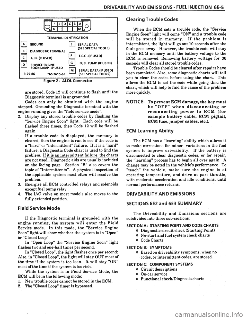
compartment (Figure 2). It has terminals which are
used in the assembly plant to check that the engine is
operating properly before it leaves the plant.
Terminal "B" is the Diagnostic terminal, and it can be
connected to terminal
"A", or ground, to enter the
Diagnostic mode, or the Field Service Mode.
The ALDL connector is also used by "ScanJ' tools to
read information from the ECM via the Serial Data
Line. Serial Data information
is used extensively
throughout the manual.
Diagnostic Mode
1
If the Diagnostic terminal is grounded with the
ignition "ON" and the engine stopped, the system will
enter the Diagnostic Mode. In this mode the ECM
will:
1. Display a Code 12 by flashing the "Service Engine
Soon" light (indicating the system is operating). A
Code 12 consists of one flash, followed by a short
pause, then two flashes in quick succession. This
code will be flashed three times. If no other codes
Page 966 of 1825
DRIVEABILITY AND EMISSIONS - FUEL INJECTION 6E-5
TERMINAL IDENTIFICATION
GROUND SERIALDATA
(SEE SPECIAL TOOLS)
DIAGNOSTIC TERMINAL
I.I.R. (IF USED) T.C.C. (IF USED)
SERVICE
ENGINE FUEL PUMP (IF USED)
SOON LAMP- IF USED
SERIAL DATA (IF USED) 3-29-86 *6S 2615-6E (SEE SPECIAL TOOLS)
Figure 2 - ALDL Connector
are stored, Code 12 will continue to flash until the
Diagnostic terminal is ungrounded.
Codes can only be obtained with the engine
stopped. Grounding the Diagnostic terminal with the
engine running gives the "field service mode".
2. Display any stored trouble codes by flashing the
"Service Engine Soon" light. Each code will be
flashed three times, then Code
12 will be flashed
again.
If a trouble code is displayed, the memory is
cleared, then the engine is run to see
if the code is
a "hard" or "intermittent" failure. If it is a "hard"
failure, a Diagnostic Code chart is used to find the
problem. If it is an intermittent failure, the charts
are not used. Diagnostic aids are usually included
on the facing page. Section
"B" also covers the
topic of "Intermittents".
A physical inspection of
the applicable system most often will resolve the
problem.
3. Energize all ECM controlled relays and solenoids
except fuel pump relay
.
4. The IAC valve on most models also moves to the
fully extended position.
Field Service Mode
If the Diagnostic terminal is grounded with the
engine running, the system will enter the Field
Service mode. In this mode, the "Service Engine
Soon" light will show whether the system is in "Open"
or
"Closed Loop".
In "Open Loop" the "Service Engine Soon" light
flashes two and one-half times per second.
In "Closed Loop", the light flashes once per second:
Also, in "Closed Loop", the light will stay OUT most of
the time
if the system is too lean. It will stay "ON"
most of the time if the system is too rich.
While the system is in Field Service Mode, the
ECM will be in the following mode:
1. New trouble codes cannot be stored in the ECM.
2. The "Closed Loop" timer is bypassed.
Clearing Trouble Codes
When the ECM sets a trouble code, the "Service
Engine Soon" light will come "ON" and a trouble code
will be stored in memory. If the problem is
intermittent, the light will go out
10 seconds after the
fault goes away. However, the trouble code will stay
in the ECM memory until the battery voltage to the
ECM is removed. Removing battery voltage for
30
seconds will clear all stored trouble codes.
Trouble Codes should be cleared after repairs have
been completed. Also, some diagnostic charts will tell
you to clear the codes before using the chart. This
allows the ECM to set the code while going thru the
chart, which will help to find the cause of the problem
more quickly.
NOTICE: To prevent ECM damage, the key must
be
"OFFn when disconnecting or
reconnecting power to
ECM (for
example battery cable,
ECM pigtail,
ECM fuse, jumper cables, etc.).
ECM Learning Ability
The ECM has a "learning" ability which allows it
to make corrections for minor variations in the fuel
system to improve driveability. If the battery is
disconnected to clear diagnostic codes, or for repair,
the "learning" process has to begin all over again.
A
change may be noted in the vehicle's performance. To
"teach" the vehicle, make sure the engine is at
operating temperature, and drive at part throttle,
with moderate acceleration and idle conditions, until
normal performance returns.
DRIVEABILITY AND EMISSIONS
SECTIONS
6E2 and 6E3 SUMMARY
The Driveability and Emissions sections are
subdivided into three sub-sections:
SECTION A: STARTING POINT AND CODE CHARTS
@ Diagnostic circuit check (Starting Point)
@ No-start and fuel system check charts
@ Code Charts
SECTION B: SYMPTOMS
e Based on driveability symptoms, when no
codes, or intermittent codes, are stored.
SECTION C: COMPONENT SYSTEMS
@ Circuit descriptions
@ On-car service
@ Functional checWDiagnosis charts
Page 968 of 1825
DRIVEABILITY AND EMISSIONS - FUEL INJECTION 6E-7
On engines that can be monitored in the open
mode, it allows certain parameters to be obtained
without changing the engine operating
characteristics. The parameters capable of being read
vary from engine family to engine family. Most
"Scan" tools are programmed so that the system will
go directly into the special mode
if the "open" mode is
not available.
ALDL (7 OK, or Special) Mode
(not used on
all engines)
In this mode, all information incorporated into a
specific
engine and ECM is obtainable. However, in
this mode the system operating characteristics are
modified as follows.
@ "Closed Loop" timers are bypassed
EST (spark) is advanced
@ IAC will control engine idle to 1000 rpm I
50 rpm (if applicable)
@ On some engines, canister purge solenoid will
be enabled
@ P/N restrict functions will be disabled.
Factory Test (Back-up or 3.9 K) Mode
(TBI, Port)
In this mode, the ECM is operating on the fuel
back-up logic and is calibrated by the Calpak or Mem-
cal. These are used to control the fuel delivery
if the
ECM fails. This mode verifies that the back-up feature
is OK. The parameters that can be read on a
"Scan"
tool in this mode are not of much use for service.
"SCAN" TOOL LIMITATIONS AND USE
The "Scan" tool allows a quick check of sensors
and switches which are inputs to the ECM. However,
on some applications the data update rate makes the
tool less effective as a voltmeter when trying to detect
an intermittent which lasts for a very short time.
However, the "Scan" tool allows one to manipulate
wiring harnesses or components under the hood while
observing the "Scan" readout. This helps in locating
intermittents with the engine not running.
intermittent Conditions
for a period of time to see if there is any change in the
readings that indicates intermittent operation.
The "Scan" tool is also a useful and quick way of
comparing operating parameters of a poorly operating
engine with a known good one. For example;
A sensor
may shift in value but not set a code. Comparing with
a known good vehicle may uncover the problem.
The "Scan" tool has the ability to save time in
diagnosis and prevent the replacement of good parts.
The key to using the "Scan" tool successfully for
diagnosis lies in the technician's ability to understand
the system he is trying to diagnose as well as an
understanding of the "Scan" tool's limitations.
Therefore, the technician should read the tool
manufacturer's operating manual to become familiar
with the operation. The following information will
describe most of the "Scan" tool positions and how
they can be helpful in diagnosis.
"SCAN" TOOL POSITIONS
The following positions may not be applicable to
all engines. See the facing page
of the diagnostic
circuit check for a particular engine to decide which
positions apply to that engine.
Mode
Check with the manufacturer to determine what
the function of this mode is. In most cases it allows the
user to place the ECM in different operating modes.
Injector Pulse Width
In this position, the reading is given in
milliseconds, which is the
"ON" time that the ECM is
commanding to the
injector(s1.
Closed LoopIOpen Loop
This position will indicate whether the engine
control system is operating in "Open Loop" or "Closed
Loop". Most systems go "Closed Loop" after a certain
amount of running time, when coolant temperature is
high enough, and the oxygen sensor becomes active.
Exhaust (RichILean Indicator)
The "Scan" tool is helpful in cases of intermittent
This indicates the O2 sensor voltage at the instant operation' The can be in and observed that the data stream is sampled. If voltage is less than
while driving the vehicle under the condition where
350 mv, the value will be lean. If above 550 mv, a rich the light comes "ON" momentarily, or the engine exhaust is indicated. driveability is poor momentarily. If the problem
seems to be related to certain areas that can be
Codes checked on the "Scan" tool, then those are the
positions that should be checked while driving the
This will display any trouble codes stored in the
vehicle. If there does not seem to be any correlation
ECM memory. between the problem and any specific circuit, the
"Scan" tool can be checked on each position, watching
Page 970 of 1825
DRIVEABILITY AND EMISSIONS - FUEL INJECTION 6E-9
ParWNelatral Switch IAC (Idle Air Control)
The indication in this mode may vary with This system is used to control engine idle speed to
manufacturer so the type of reading for a particular the desired rpm, for different operating conditions. In
tool should be checked in the operator's manual. The this mode, the numbers will indicate the position to
important thing is that the the reading changes state which
the ECM has moved the valve pintle. The ECM
(switches) when the gear selector is moved from moves
the IAC in counts, or steps, and the number of
paridneutral to drive or reverse. these counts are displayed on a "Scan" tool.
"Trque Convertor Clutch (TCC)
In this position, the tool will indicate when the
TCC has been commanded by the ECM to turn "ONJ'.
This does not necessarily mean that the clutch was
engaged but only that the
ECM grounded the circuit
internally. The best way to determine if the clutch has
engaged is to monitor engine rpm when the TCC
comes "ON".
EGR (Duty Cycle)
The EGR system uses a valve to feed a small
amount of exhaust gas back into the intake manifold
to control formation of NO,. Like all ECM outputs, the
"Scan" tool only indicates that the ECM has
commanded the function, and does not indicate that
the function has really happened.
EGR Position
This indicates the position of the EGR pintle.
Integrator and Block Learn
Normal readings for these positions are around
128. If higher, it indicates that the ECM is adding fuel
to the base fuel calculation because the system is lean,
and if the numbers are below 128, the ECM is taking
out fuel from the base calculation because the system
is rich. The integrator gives short term corrective
action, while the block learn portion (which is a long
term correction) will only change if the integrator has
seen a condition which lasts for a calibrated period of
time.
Block Learn Multiplier (BLM) Cell - or -
Block Learn Memory (BLM)
There are up to sixteen different cells,
corresponding to ranges of rpm and engine load
(indicated by MAF or MAP signals), and other
conditions, such as
A/C or P/N switch "ON" or "OFF",
etc. The ECM learns how much adjustment is needed
in each cell, and retains it in memory, so that the
adjustment will immediately be made when the
engine operates in that cell (or
rpmlload range). This
parameter will display what cell the ECM is currently
using for the fuel calculation.
Desired RPM
This indicates the rpm to which the ECM is trying
to control the idle.
Shift Light
This displays "yes" when the ECM is commanding
the shift light to turn "ON".
PPSW (Pump Prime Switch)
This is the voltage on the fuel pump feed circuit.
The ECM will adjust fuel injector base pulse width
from this voltage value rather than from battery
voltage.
NC Request
The state of the A/C signal line to the ECM is
shown. It should read "yes" whenever the
IVC is
requested.
NC Clutch
"ON" is displayed when the ECM has commanded
the
A/C clutch "ON".
Knock Retard
This indicates the number of degrees the ECM is
retarding the electronic spark timing (EST).
Knock Signal
This displays a "yes" when knock is detected by
the ECM, and a "no" when knock is not detected.
Battery Voltage
This displays the battery voltage detected at the
ECM ignition input.
Fan
"ON" is displayed when the cooling fan has been
commanded "ON".
Page 972 of 1825
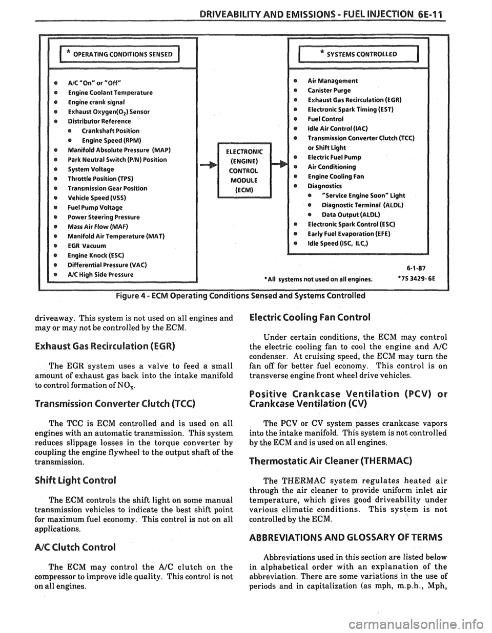
DRIVEABILITY AND EMISSIONS - FUEL INJEC"F0N 6E-11
@ A/% "On" or "Off" r Air Management
r Engine Coolant Temwrature r Canister Purge
@ Engine crank signal r Exhaust Gas Recirculation (EGR)
@ Exhaust Oxygen(02) Sensor @ Electronic Spark Timing (EST)
r Distributor Reference @ Fuel Control
@ Crankshaft Position @ Idle Air Control (lAC)
@ Engine Speed (RPM) Transmission Converter Clutch (TCC)
Manifold Absolute Pressure (MAP)
@ Park Neutral Switch (PB) Position @ Electric Fuel Pump
r System Voltage Air Conditioning
r Throttle Position (TPS) @ Engine Cooling Fan
r Transmission Gear Position
r Vehicle Speed (VSS) @ "Service Engine Soon" Light
@ Fuel Pump Voltage @ Diagnostic Terminal (ALDL)
r Power Steering Pressure @ Data Output (ALDL)
Mass Air Flow (MAF) @ Electronic Spark Control (ESC)
@ Manifold Air Temperature (MAT) @ Early Fuel Evaporation (EFE)
r EGR Vacuum @ Idle Speed (ISC, ILC,)
@ Engine Knock (ESC)
r Differential Pressure (VAC) 6-1-87
*7S
3429- 6E
Figure
4 - ECM Operating Conditions Sensed and Systems Controlled
driveaway. This system is not used on all engines and Electric Cooling Fan Control
may or may not be controlled by the ECM.
Under certain conditions, the
ECM may control
Exhaust Gas Recirculation (ECR) the electric cooling fan to cool the engine and A/C
condenser. At cruising speed, the ECM may turn the
The
EGR system uses a valve to feed a small fan
off for better fuel economy. This control is on
amount of exhaust gas back into the intake manifold transverse
engine front wheel drive vehicles.
to control formation of
NO,.
Positive Crankcase Ventilation (PCV) or
Transmission Converter
Clutch (TCC) Crankcase Ventilation (CV)
The TCC is ECM controlled and is used on all
engines with an automatic transmission. This system
reduces slippage losses in the torque converter by
coupling the engine flywheel to the output shaft of the
transmission.
Shift Light Control
The ECM controls the shift light on some manual
transmission vehicles to indicate the best shift point
for maximum fuel economy. This control is not on all
applications.
NC Clutch Control
The ECM may control the AJC clutch on the
compressor to improve idle quality. This control is not
on all engines. The
PCV or CV system passes crankcase vapors
into the intake manifold. This system is not controlled
by the
ECM and is used on all engines.
Thermostatic Air Cleaner (THERMAC)
The THERMAC system regulates heated air
through the air cleaner to provide uniform inlet air
temperature, which gives good driveability under
various climatic conditions. This system is not
controlled by the
ECM.
ABBREVIATIONS AND GLOSSARY OF TERMS
Abbreviations used in this section are listed below
in alphabetical order with an explanation of the
abbreviation. There are some variations in the use of
periods and in capitalization (as mph,
m.p.h., Mph,
Page 973 of 1825
6E-12 DRIVEABILITY AND EMISSIONS - FUEL INJECUION
and MPH) for abbreviations used in this Section, but
all types are acceptable.
NA/F - AI WFUEL (NF RATIO)
A.I.R.
- AIR INJECTOR REACTION SYSTEM - Air
flow from pump is directed into engine exhaust
manifold
and/or converter to reduce exhaust
emissions.
ALDL - ASSEMBLY LINE DIAGNOSTIC LINK - Used
at assembly to evaluate Computer Command Control,
and for service to flash the "Service Engine Soon"
light
if there are trouble codes. It also is used by
"Scan" tools to obtain ECM serial data.
BARO - BAROMETRIC ABSOLUTE PRESSURE
SENSOR
- Reads atmospheric pressure.
B + - Battery Positive Terminal (12 Volts) or
system voltage with the engine running
(approximately 13.8
v.)
CALPAK - A device used with fuel injection to
allow fuel delivery in the event of a PROM or ECM
malfunction.
CALIBRATOR - (PROM) - An electronic component
that can be
specifically programmed to meet engine
operating requirements for a
specific vehicle model.
It plugs into the Engine Control Module
(ECM).
CCC - COMPUTER COMMAND CONTROL - has an
electronic control module to control airlfuel and
emission systems.
CLCC - CLOSED LOOP CARBURETOR CONTROL -
Used to describe oxygen sensor to ECM to MIC
solenoid circuit operation.
C3I - Computer Controlled Coil Ignition. Produces
the ignition spark without the aid of an ignition
distributor.
CCP - CONTROLLED CANISTER PURGE - ECM
controlled solenoid valve that permits manifold
vacuum to purge the evaporative emissions from the
charcoal canister.
CID - CUBIC INCH DISPLACEMENT - Used to
describe engine size.
UL OR ULOOP - "CLOSED LOOP" - Describes ECM
fuel control when using oxygen sensor information.
COOLANT TEMPERATURE SENSOR - Device that
senses the engine coolant temperature, and passes
that information to the engine control module.
CONV. - CATALYTIC CONVERTER, THREE-WAY -
EXHAUST CONVERTER. Containing platinum and
palladium to speed up conversion of
HC and CO, and
rhodium to accelerate conversion of NO,.
CO - CARBON MONOXIDE - One of the pollutants
found in engine exhaust.
6V - CRANKCASE VENTlhaflON - Prevents fumes
in crankcase from passing into the atmosphere, by
drawing them into the intake manifold and burning
them in the the combustion process.
DIAGNOSTIC CODE - Pair of numbers obtained
from flashing "Service Engine Soon" light or
displaying on a "Scan" tool. This code can be used to
determine the system malfunction.
DIAGNOSTIC TERM. - Lead of ALDL Connector
which is grounded to get a Trouble Code.
It is
grounded with the engine running to enter the "Field
Service Mode".
DIS - Direct Ignition System. Produces the
ignition spark without the aid of an ignition
distributor.
DVM (10 Meg.) - Digital Voltmeter with 10 Million
ohms resistance
- used for measurement in electronic
systems.
DWELL - The amount of time (recorded on a dwell
meter in degrees of crankshaft rotation) that current
passes through a closed switch; for example, ignition
contact points or internal switch in an electronic
control module.
EAC - ELECTRIC AIR CONTROL - Used on A.I.R.
system to direct air flow to air switching valve or to
atmosphere.
EAS - ELECTRIC AIR SWITCHING - used to direct air
flow to catalytic converter or exhaust ports of the
engine.
ECM - ENGINE CONTROL MODULE (ELECTRONIC) -
A metal case (located in passenger compartment)
containing electronic circuitry which electrically
controls and monitors airlfuel and emission systems
on computer command control, and turns
"ON" the
"Service Engine Soon" light when a malfunction
occurs in the system.
EFI - ELECTRONIC FUEL INJECTION - Computer
Command Control using throttle body fuel injection.
EGR - EXHAUST GAP REClRCUbATlON - Method of
reducing NO, emission levels by causing exhaust gas
to be added to airlfuel mixture in combustion
chamber, thus cooling combustion.
EECS - EVAPORATIVE EMISSIONS CONTROL
SYSTEM
- Used to prevent gasoline vapors in the fuel
tank from entering the atmosphere.
EFE - EARLY FUEL EVAPORATION - Method of
warming the intake manifold during cold engine
operation. Provides efficient airlfuel mixing.
ENERGIZEIDE-ENERGIZE - When current is passed
through a coil (energized) such as the canister purge
solenoid, the plunger is pulled into the solenoid.