1988 PONTIAC FIERO height
[x] Cancel search: heightPage 227 of 1825
30-8 WEAR SUSPENSION
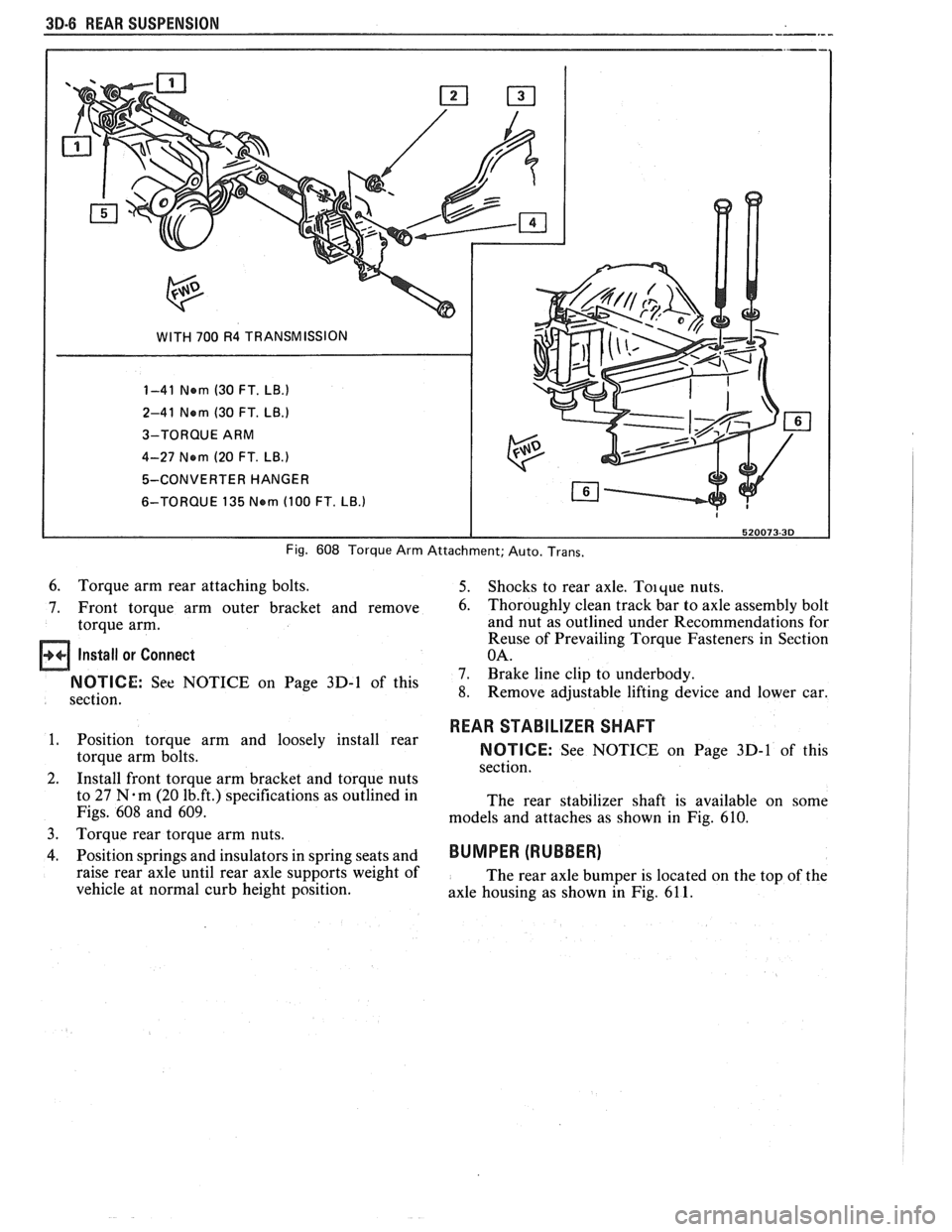
WITH 700 R4 TRANSMISSION
1-41 Nern (30 FT.
LB.)
2-41 Nern (30 FT. LB.)
3-TORQUE ARM
4-27 Nern
(20 FT. LB.)
5-CONVERTER HANGER
6-TORQUE 135
Nern (100 FT. LB.)
Fig. 608 Torque Arm Attachment; Auto. Trans.
6. Torque arm rear attaching bolts. 5. Shocks to rear axle. Toique nuts.
7. Front torque arm outer bracket and remove
6. Thoroughly clean track bar to axle assembly bolt
torque arm. and nut
as outlined under Recommendations for
Reuse of Prevailing Torque Fasteners in Section
Install or Connect OA.
7. Brake line clip to underbody. On Page 3D-1 of this 8. Remove adjustable lifting device and lower car.
section.
1. Position torque arm and loosely install rear
torque arm bolts.
2. Install front torque arm bracket and torque nuts
to 27
N.m (20 1b.ft.) specifications as outlined in
Figs.
608 and 609.
3.
Torque rear torque arm nuts.
4. Position springs and insulators in spring seats and
raise rear axle until rear axle supports weight of
vehicle at normal curb height position.
REAR STABILIZER SHAFT
NOTICE: See NOTICE on Page 3D-1 of this
section.
The rear stabilizer shaft is available on some
models and attaches as shown in Fig.
610.
BUMPER (RUBBER)
The rear axle bumper is located on the top of the
axle housing as shown in Fig.
61 1.
Page 244 of 1825
PROPELLER SHAFT $A-3
B. If companion flange run-out is over 0.15mm (.006
in.) but less than 0.28mm (.011 in.) and balance
weight is at or near low point of companion flange
run-out, no further action is required.
If balance weight is not at or near low point of
companion flange run-out, remove weight.
6. If companion flange run-out is over 0.28mm (.011
in.), but no greater than 0.38mm (.015 in.) and
balance weight is at or near low point of
companion flange run-out, no further action is
required.
If balance weight is not at or near low point of
companion flange
runout, remove weight and
reindex companion flange until run-out is 0.25
mm
(.010 in.) or less.
If impossible to achieve
0.25mm (.010 in.) or less
run-out, install a new companion flange and
recheck for
0.25mm (.010 in.) or less run-out.
Service replacement companion flanges are not
equipped with balance weights and no weights
should be added.
UNIVERSAL JOINT ANGLE MEASUREMENT
When torque is transmitted through any ordinary
universal joint, the driven yoke fluctuates slightly in
speed. In other words, although the driving yoke
rotates at a constant speed, the driven yoke speeds up
and slows down twice per revolution. This flucutation
of the driven yoke is in direct proportion to the angle
through which the universal joint is operating; the
greater the angle, the greater the fluctuation.
Whenever two universal joints are used, this
fluctuation effect can be eliminated by staggering the
joints so that the two driving yokes are 90 degrees apart
provided the two joints are transmitting torque
through the same angle.
Therefore, when two universal joints are used, the
angles through which they operate must be very nearly the
same. This allows the alternate acceleration and decelera-
tion of one joint to be offset by the alternate acceleration
and deceleration of the second joint. When the two joints
do not run at approximately the same angle, operation is
rough and an objectionable vibration is produced.
The actual optimum angles desired must take into
consideration the effects of various passenger loadings
and rear axle windup during acceleration; therefore, it
is unlikely that the front and rear universal joint angles
will be found to be the same in actual practice.
In addition, universal joints are designed to
operate safely and efficiently within certain angles. If
the designed angle is exceeded, the joint may be broken
or otherwise damaged.
The front universal joint angle is actually the
angle between the engine-transmission centerline and
the propeller shaft centerline. This angle is determined
by the design of the frame assembly and may be altered
by adding or removing shims between the transmission
and the transmission mount.
Adding one shim at the transmission mount will
decrease the transmission universal joint angle by
1/2"
and increase differential universal joint angle by 1/4".
If one shim is removed the tranmission angle will
increase
1/2" and decrease differential angle I/@. The
production transmission mount bolt is an
M10-1.5 x 35
mm. When installing two or more shims, an
M10-1.5
x 50 mm bolt must be used.
All complaints of propeller shaft vibrations
should be accompanied by rear trim height
measurements at curb weight. An incorrect trim height
may cause some vibration. If vibration is severe
enough, removal or installation of spring shims may be
required. If any irregular roughness or vibration is
detectable in the drive line, the front and rear universal
joint angles should be checked. Should the vehicle
become involved in a severe rear end collision, or
should the rear axle carrier be replaced, the rear
universal joint angle should be checked and control
arms should be replaced if necessary.
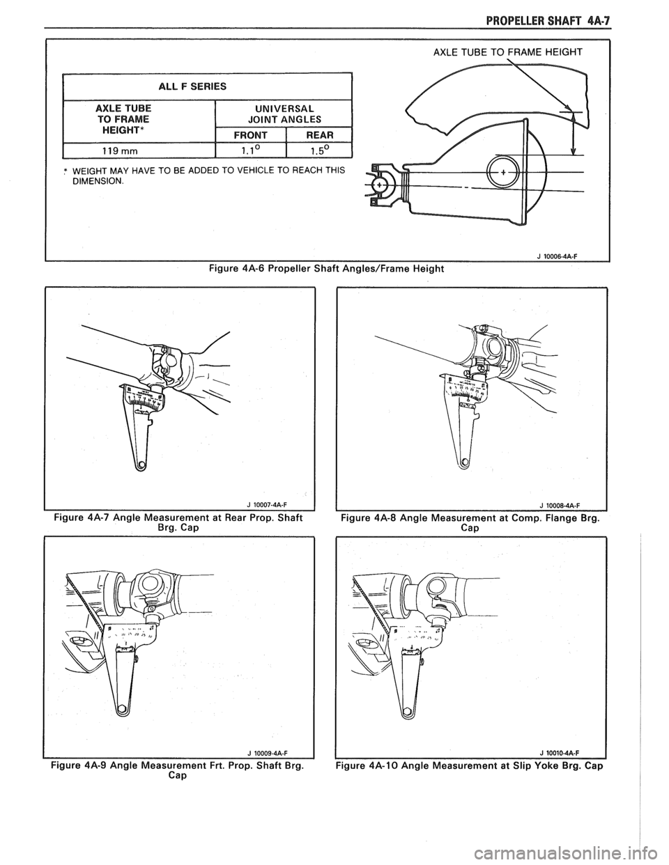
Figure 4A-6
This method can be used with the vehicle over a
pit or on a drive-on platform hoist, as long as the
vehicle is at curb weight with a full tank of gasoline.
Bounce vehicle up and down to assure curb height.
Before universal joint angles can be checked, the
measurements specified (the distance between the top
of the axle tube and the bottom of the frame) must be
met. To insure an accurate measurement, weight may
have to be added to the vehicle to reach these
specifications.
Readings should be taken at the following
locations in the following manner.
Angle Measurement at Rear Universal Joint
Figures 4A-7 and 4A-8
1. Place inclinometer J 23498-A on rear propeller
shaft bearing cap. Center bubble in sight glass and
record measurement. Bearing cap must be straight
up and down and free of dirt or other foreign mate-
rial to obtain an accurate measurement.
2. Rotate propeller shaft 90 degrees and place
inclinometer on the companion flange bearing
cap. Center bubble in sight glass and record
measurement.
3. Subtract smaller figure from larger figure to
obtain existing rear universal joint angle.
Angle Measurement at Front Universal Joint
Figures 4A.9 and 4A- 10
1. Place inclinometer on front propeller shaft
bearing cap. Center bubble in sight and record
measurement.
2. Rotate propeller shaft 90 degrees and place
inclinometer on the slip yoke bearing cap. Center
bubble on sight glass and record measurement.
3. Substract smaller figure from larger figure
lo
obtain existing front universal joint angle.
Page 248 of 1825
PROPELLER SHAFT 4A-7
* WEIGHT MAY HAVE TO BE ADDED TO VEHICLE TO REACH THIS DIMENSION.
Figure 4A-6 Propeller Shaft Angles/Frame Height
Figure 4A-7 Angle Measurement at Rear Prop. Shaft
Brg. Cap
Figure
414-9 Angle Measurement Frt. Prop. Shaft Brg.
Cap
Figure 4A-8 Angle Measurement at Comp. Flange Brg.
Cap
Figure 4A-10 Angle Measurement at Slip Yoke Brg. Cap
Page 342 of 1825
POWER HEAD ASSEMBLY 5D2-7
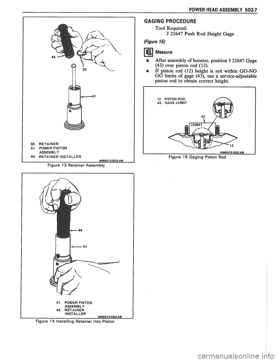
30. RETAINER
41. POWER PISTON
ASSEMBLY
44, RETAINER INSTALLER HMO01 3-5D2-AB
Figure 13 Retainer Assembly
GAGING PROCEDURE
Tool Required:
J 22647 Push Rod Height Gage
(Figure 15)
e After assembly of booster, position J 22647 Gage
(43) over piston rod (12).
e If piston rod (12) height is not within GO-NO
GO limits of gage
(43), use a service-adjustable
piston rod to obtain correct height.
12. PISTON ROD 43. GAGE J22647
43 b
Figure 15 Gaging Piston Rod
41. POWER PISTON
ASSEMBLY
44. RETAINER
INSTALLER
HM0014-5D2.AB
Figure 14 Installing Retainer Into Piston
Page 364 of 1825
2.8 LITER V.6 6A2.13
Torque bolts as shown in Figure 6A2-15.
4. Install
push rods and loosely retain with rocker
arms. Make sure lower ends of
pushrods are in
lifter seats.
5. Install intake manifold.
6. Raise vehicle.
7. Install dipstick tube bracket.
8. Connect exhaust pipe
to exhaust manifold flange.
9. Lower vehicle.
10. Adjust
valve lash as previously outlined.
11. Continue
following intake manifold installation
for build up.
Removal (Right)
Remove intake manifold as previously outlined.
Raise vehicle.
Disconnect exhaust pipe.
Drain engine block.
Lower vehicle.
Loosen rocker arms until able to remove push
rod.
Remove serpentine belt.
Remove tensioner.
Remove A.I.R. bracket.
Remove generator bracket.
Remove head bolts.
Remove head.
Installation (Right)
The gasket surfaces on both the head and cylinder
case
deck must be clean of any foreign matter and free
of nicks of heavy scratches. Cylinder bolt threads in the
case and threads on the cylinder head bolts must be
clean. Dirt will affect bolt torque.
1. Place the gasket in position, over the dowel pins,
with the note "This Side Up" showing.
2. Install cylinder head.
3. Coat cylinder head bolt threads with sealer,
#lo52080 or equivalent, and install bolts.
Torque bolts as shown in (Figure
6A2-15).
Install push rods and loosely retain with rocker
arms. Make sure lower ends of push rods are in
lifter seats.
Install intake manifold.
Raise vehicle.
Install exhaust pipe to exhaust manifold flange.
Lower vehicle.
Adjust valve lash as previously outlined.
Install AIR bracket.
Install tensioner.
Install generator bracket.
Continue following intake manifold installation
for build up.
Disassembly
1. With cylinder head removed, remove rocker arm
nuts, balls and rocker arms (if not previously
done).
2. Using tool J-8062, compress the valve springs and
remove valve keys. Release the compressor tool and
remove spring caps, oil shedders, springs and
damper assemblies, then remove oil seals.
3. Remove valves from cylinder head and place
them in a rack so they can be installed in their
original positions.
Cleaning and Inspection
Clean all carbon from combustion chambers and
valve ports using 'tool
5-8089.
Thoroughly clean valve guides using 5-8 10 1.
Clean all carbon and sludge from push rods,
rocker arms and push rod guides.
Clean valve stems and heads on a buffing wheel.
Clean carbon deposits from head gasket mating
surface.
Inspect cylinder head for cracks in the exhaust
ports, combustion chambers, or external cracks
to the water jacket.
Inspect the valves for burned heads, cracked faces
or damaged stems.
NOTICE: Excessive valve stem to bore clearance
will cause high oil consumption and may cause
valve breakage. Insufficient clearance will result in
noise and sticky functioning of the valve and
disturb engine smoothness.
8. Measure valve stem clearance as follows:
a. Clamp
a dial indicator on one side of the
cylinder head. Locate the indicator so that
movement of the valve stem from side to
side (crosswise to the head) will cause direct
movement of the indicator stem. The
indicator stem must contact the side of the
valve stem just above the guide.
b. Drop
the valve head
1.5mm off the valve
seat.
c. Move
the stem of the valve from side to side,
using light pressure, to obtain a clearance
reading. If clearance exceeds specifications,
it will be necessary to ream valve guides for
oversize valves. Service valves are available
in std., 089,
.394 and .775mm O.S. sizes.
9. Check
valve spring tension with tool J-8056,
spring tester. Springs should be compressed to the
specified height and checked against the
specifications chart. Springs should be replaced if
not within 44
N (10 Ibs.) of the specified load
(without dampers).
10. Inspect
rocker arm studs for wear or damage.
ROCKER ARM STUDS
Cylinder heads use threaded rocker arm studs.
Rocker arm studs that have damaged threads should
be replaced with new studs. If, for some reason, the
threads in the head
are damaged or stripped, the head
can be retapped, and a helical type insert added. If such
an insert is not available, the head should be replaced.
VALVE GUIDES
Valves with oversize stems are available in .089,
,394 and ,775mm over sizes. To ream the valve guide
Page 365 of 1825
BA2-14 2.8 LITER V-6
bores for oversize valves use tool 5-5330-1, 2 or 3,
respectively.
VALVE SEATS
Reconditioning the valve seats is very important,
because the seating of the valves must be perfect for the
engine to deliver the power and performance designed
into it.
Another important factor is the cooling of the
valve heads. Good contact between each valve and its
seat in the head is imperative to insure that the heat in
the valve head will be properly carried away.
Several different types of equipment are available
for reseating valve seats. The recommendations of the
manufacturer of the equipment being used should be
carefully followed to attain proper results.
VALVES
Valves that are pitted can be refaced, to the
proper angle, insuring correct relation between the
head and stem, on a valve
refacing machine. Valve
stems which show excessive wear, or valves that are
warped excessively should be replaced. When a valve
head which is warped excessively is
refaced, a knife
edge will be ground on part or all of the valve head due
to the amount of metal that must be removed to
completely
reface the valve. Knife edges lead to
breakage, burning or preignition due to heat localizing
on this knife edge. If the edge of the valve head is less
than
.8mm thick after grinding, replace the valve.
Several different types of equipment are available
for
refacing valves. The recommendations of the
manufacturer of the equipment being used should be
carefully followed to attain the proper results.
Assembly
Insert a valve in the proper port.
Install a valve stem seal over the valve stem and
valve guide base inlet only.
Drop an oil shedder and valve rotator over the
exhaust and a valve spring cap over the valve
spring.
Using tool
5-8062 compress the valve spring.
Install the square cut
"0" ring around the valve
stem in the lower groove, making sure it is not
twisted.
Insert valve, stem key locks and release tool.
Install the valve locks and release the compressor
tool making sure that the locks seat properly in
the upper groove of the valve stem. Grease may
be used to hold the locks in place while releasing
the compressor tool.
Install the remaining valves.
Check each valve stem oil seal by placing valve
stem leak detector, tool J-23994, over the end of
the valve stem and against the cap. Operate the
vacuum pump and make sure no air leaks pass the
seal.
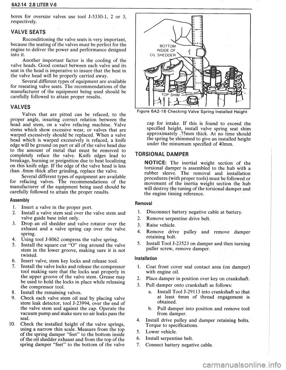
Check the installed height of the valve springs,
using
a narrow thin scale. Measure from the top
of the spring damper "feet" to the bottom inside
of the oil shedder exhaust and from the top of the
spring damper "feet" to the bottom of the valve
Figure 6A2-16 Checking Valve Spring Installed Height
cap for intake. If this is found to exceed the
specified height, install valve spring seat shim
approximately
.75mm thick. At no time should
the spring be shimmed to give an installed height
under the
minumum specified of 40mm.
TORSIONAL DAMPER
NOTICE: The inertial weight section of the
torsional damper is assembled to the hub with a
rubber sleeve. The removal and installation
procedures (with proper tools) must be followed or
movement of the inertia weight section the hub
will destroy the tuning of the torsional damper and
the engine timing reference.
Removal
1.
Disconnect battery negative cable at battery.
2. Remove serpentine drive belt.
3. Raise vehicle.
4. Remove drive pulley and remove damper
retaining bolt.
5. Install Tool J-23523 on damper and then turning
puller screw, remove damper.
Installation ,
1.
Coat front cover seal contact area (on damper)
with engine oil.
2. Place damper in position over key on crankshaft.
3. Pull damper onto crankshaft as follows:
a. Install
Tool J-29 1 13 into crankshaft so that
at least 6mm of thread engagement is
obtained.
b. Pull damper into position and remove tool
from damper.
4. Install drive pulley and damper retaining bolts.
Torque to specifications.
5. Lower vehicle.
6. Install serpentine belt.
7. Connect battery negative cable.
Page 378 of 1825
COMPRESSION Groove Clearance
............................................................................................................................ Top .030..070
................................................................................ Second .................................... .... .040.. 095
Gap ................................................................................................................................. Top .25..50
............................................................................................................................ Second .25..50
OIL
...................................................................................................... . Groove Clearance 0 199 Max
Gap
................................................................................................................................ 0.51-1.40
Piston Pin
DIAMETER ....................................................................................................... 22.9937-23.0015
........................................................................................................... CLEARANCE .0065-.009 1
FIT IN ROD
..................................................................................................... .0187-. 0515 Press
Camshaft
LIFT
Intake
................................................................................................................................... 6.67
Exhaust
.................................................................................................................................. 6.94
............................................................. ............................ JOURNAL DIAMETER .. 47.44-47.49
............................................................................................. JOURNAL CLEARANCE .026- . 101
Crankshaft
MAIN JOURNAL
Diameter All
67.241-67.265mm
............................................................................................................................. Taper 005 Max .
................................................................................................................ Out of Round 005
Max .
.................................................................................. MAIN BEARING CLEARANCE 04
1-.08 1
................................................................ MAIN THRUST BEARING CLEARANCE .054..084
...................................................................................... CRANKSHAFT END PLAY .06-. 2 1mm
CRANK PIN
Diameter
..................................... ... ......................................................................... 50.784-50.758
............................................................................................................................. Taper 005 Max .
............................................................................................................ Out of Round 005
Max .
.................................................... ROD BEARING CLEARANCE ......................... .. 03 5..095
................................................................................................ ROD SIDE CLEARANCE .16-. 44
Valve System
LIFTER ......................... .. ........................................................................................... Hydraulic
......................................................................................................... ROCKER ARM RATIO 1.5. 1
............................................................................... VALVE LASH 1- 1/2 Turns From Zero Lash
FACE ANGLE
........................................................................................................................... 45"
SEAT ANGLE ......................................................................................................................... 46"
....................................................................................................................... SEAT RUNOUT 05"
SEAT WIDTH
Intake
........................................................................................................................ 1.25-1.50
......................................................................................................................... Exhaust 1.60- 1.90
............................................................... STEM CLEARANCE ..................................... ... .026-. 068
VALVE SPRING
Free Length
......................................................................................................................... 48.5
Pressure N
. m
Closed
....................... .. .......................................................................................... 391 @40
Open
......................................................................................................................... 867 @30
Installed Height
........................................................................................................................ 40
DAMPER
........................................................................................................................... Free Length 47.2
Page 392 of 1825
V-8 ENGINE 6A3-13
reading. If clearance exceeds specifications,
it will be necessary to ream valve guides for
oversize valves.
e Service valves are available in standard,
.003", .015" and .030n oversize.
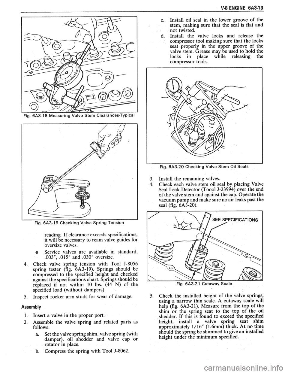
4. Check valve spring tension with Tool
5-8056
spring tester (fig. 6143-19). Springs should be
compressed to the specified height and checked
against the specifications chart. Springs should be
replaced if not within 10 lbs. (44
N) of the
specified load (without dampers).
5. Inspect rocker arm studs for wear of damage.
Assembly
1. Insert a
valve in the proper port.
2. Assemble the valve spring and related parts as
follows:
a. Set
the valve spring shim, valve spring (with
damper), oil shedder and valve cap or
rotator in place.
b. Compress the spring with Tool J-8062. c.
Install oil seal in the lower groove of the
stem, making sure that the seal is flat and
not twisted.
d. Install the valve locks and release the
compressor tool making sure that the locks
seat properly in the upper groove of the
valve stem. Grease may be used to hold the
locks in place while releasing the
compressor tools.
Fig. 6A3-20 Checking Valve Stem Oil Seals
3. Install the remaining valves.
4. Check each
valve stem oil seal by placing Valve
Seal Leak Detector
(Too01 9-23994) over the end
of the valve stem and against the cap. Operate the
vacuum pump and make sure no air leaks past the
seal (fig.
6A3-20).
Fig. 6A3-2 1 Cutaway Scale
5. Check the installed height of the valve springs,
using a narrow thin scale. A cutaway scale will
help (fig.
6A3-21). Measure from the top of the
shim or the spring seat to the top of the oil
shedder. If this is found to exceed the specified
height, install a valve spring seat shim
approximately 1/16"
(1.6mm) thick. At no time
should the spring be shimmed to give an installed
height under the minimum specified.