1988 PONTIAC FIERO height
[x] Cancel search: heightPage 409 of 1825
6A3-30 V-8 ENGINE
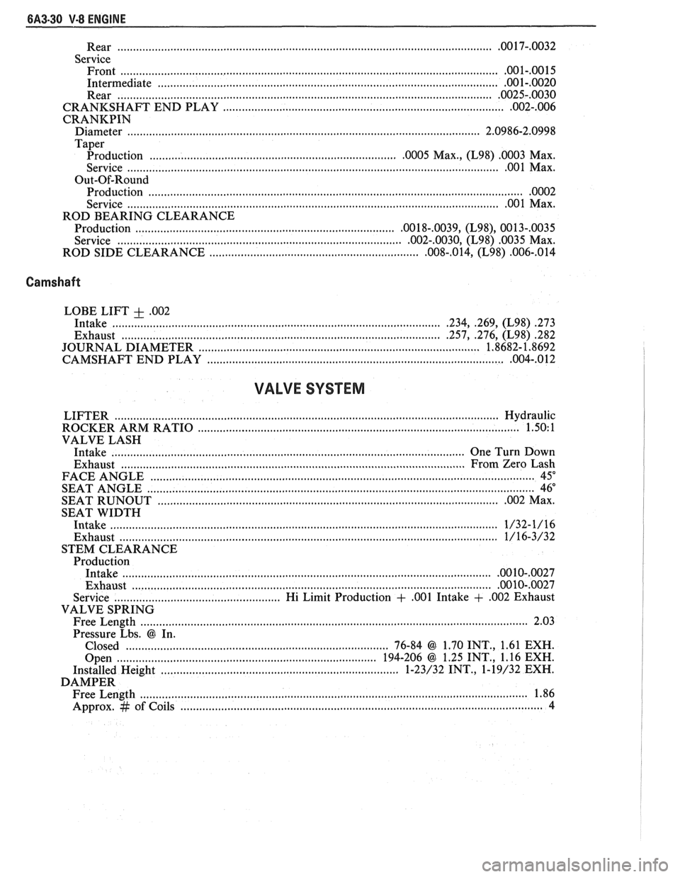
.............................................................................................. Rear ................... .. .OO 17-.0032
Service Front
......................................................................................................................... .001-.0015
Intermediate ............................................................................................................ .001-.0020
Rear ....................................................................................................................... .0025-.0030
............................................................. CRANKSHAFT END PLAY ....................... .. .002-.006
CRANKPIN
Diameter ........................... .. ................................................................................. 2.0986-2.0998
Taper
................................................ Production ....................... .. .0005 Max., (L98) .0003 Max.
............................................................................. Service ............................ .. ...... .... .OO 1 Max.
Out-Of-Round Production
....................................................................................................................... .0002
................................................................................... Service ............................ .. .00 1 Max.
ROD BEARING CLEARANCE
Production
................................................................................ ,0018-.0039, (L98), 0013-,0035
................................................... Service ................................. ....... .002-.0030, (L98) .0035 Max.
ROD SIDE CLEARANCE
............................................................... ,008-.014, (L98) .006-,014
Camshaft
LOBE LIFT + .002
Intake ..................... .. .......................................................................... .234, .269, (L98) .273
Exhaust ................................................................................................. .257, .276, (L98) 282
....................................................... JOURNAL DIAMETER .................... .... ... 1.8682- 1.8692
................................................................. CAMSHAFT END PLAY ...................... .. ,004-.012
VALVE SYSTEM
LIFTER ......................................................................................................................... Hydraulic
ROCKER ARM RATIO
................................................................................................. 1.50: 1
VALVE LASH
Intake
............................................................................................................. One Turn Down
Exhaust
..................................... ... ...................................................................... From Zero Lash
FACE ANGLE
..................... ... ............................................................................................. 45"
.......................................................................................................................... SEAT ANGLE 46"
SEAT
RUNOUT ............................................................................................................. .002 Max.
SEAT WIDTH
Intake
.................................... .... .................................................................................... 1/32-1/16
Exhaust ......................................................................................................................... 1/16-3/32
STEM CLEARANCE
Production
Intake
.................................................................................................................... .0010-,0027
Exhaust .................................................................................................................. .00 10-.0027
Service .................................................. Hi Limit Production + ,001 Intake + ,002 Exhaust
VALVE SPRING
Free Length
......................................................................................................................... 2.03
Pressure Lbs.
@ In.
Closed
.................................................................................... 76-84 @ 1.70 INT., 1.61 EXH.
Open
............................................................................... 194-206 @ 1.25 INT., 1.16 EXH.
Installed Height
....................... .. ............................................. 1-23/32 INT., 1-19/32 EXH.
DAMPER Free Length
................... .. ............................................................................................... 1.86
Approx.
# of Coils .................................................................................................................. 4
Page 1070 of 1825
AUTOMATIC TRANSMISSION 700-R4-19
- Steel for heat damage or surface finish
damage
Reaction carrier assembly (681) for
- pinion gear damage
- excessive pinion washer wear (end play -20-.
61 mm/.008-.024 in.)
- proper pinion staking
- keystoned pinion gears (pinions must turn
free)
- damaged or worn thrust bearing
To check the captive thrust bearing in the
carrier for wear, place a bushing or an
output shaft sleeve on the bearing race (do
not contact the pinion gears) and turn it
with the palm of your hand. Any
imperfections will be felt through the
bushing.
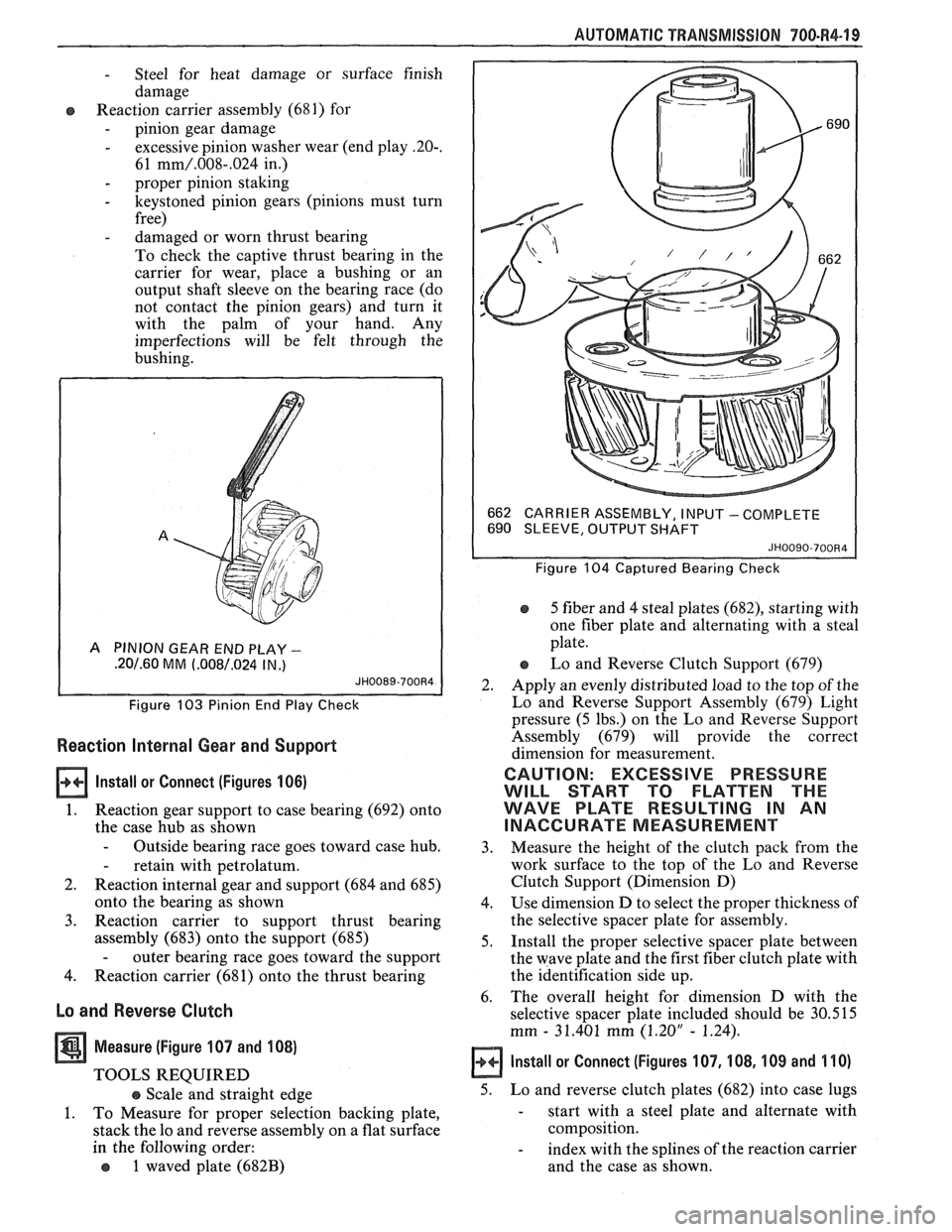
A PINION GEAR END PLAY -
.20/.60 MM (.008/.024 IN .)
Figure 103 Pinion End Play Check
Reaction Internal Gear and Support
lnstall or Connect (Figures 106)
1. Reaction gear support to case bearing (692) onto
the case hub as shown
- Outside bearing race goes toward case hub.
- retain with petrolatum.
2. Reaction internal gear and support (684 and 685)
onto the bearing as shown
3. Reaction carrier to support thrust bearing
assembly (683) onto the support (685)
- outer bearing race goes toward the support
4. Reaction carrier (681) onto the thrust bearing
Lo and Reverse Clutch
Measure (Figure 107 and 108)
TOOLS REQUIRED
e Scale and straight edge
1. To Measure for proper selection backing plate,
stack the lo and reverse assembly on a flat surface
in the following order:
o 1 waved plate (682B)
662
CARRIER ASSEMBLY, I NPU'T - COMPLETE
690 SLEEVE, OUTPUT SHAFT
JH0090-700R4
Figure 104 Captured Bearing Check
5 fiber and 4 steal plates (682), starting with
one fiber plate and alternating with a steal
plate.
Lo and Reverse Clutch Support (679)
2. Apply an evenly distributed load to the top of the
Lo and Reverse Support Assembly (679) Light
pressure (5 lbs.) on the Lo and Reverse Support
Assembly (679) will provide the correct
dimension for measurement.
CAUTION: EXCESSIVE PRESSURE
WILL START TO FLATTEN THE
WAVE PLATE RESULTING IN AN
INACCURATE MEASUREMENT
3. Measure
the height of the clutch pack from the
work surface to the top of the Lo and Reverse
Clutch Support (Dimension D)
4. Use dimension D to select the proper thickness of
the selective spacer plate for assembly.
5. Install the proper selective spacer plate between
the wave plate and the first fiber clutch plate with
the identification side up.
6. The
overall height for dimension D with the
selective spacer plate included should be 30.515
mm
- 31.401 mm (1.20" - 1.24).
Install or Connect (Figures 107, 108, 109 and 110)
5. Lo and reverse clutch plates (682) into case lugs
- start with a steel plate and alternate with
composition.
- index with the splines of the reaction carrier
and the case as shown.
Page 1084 of 1825
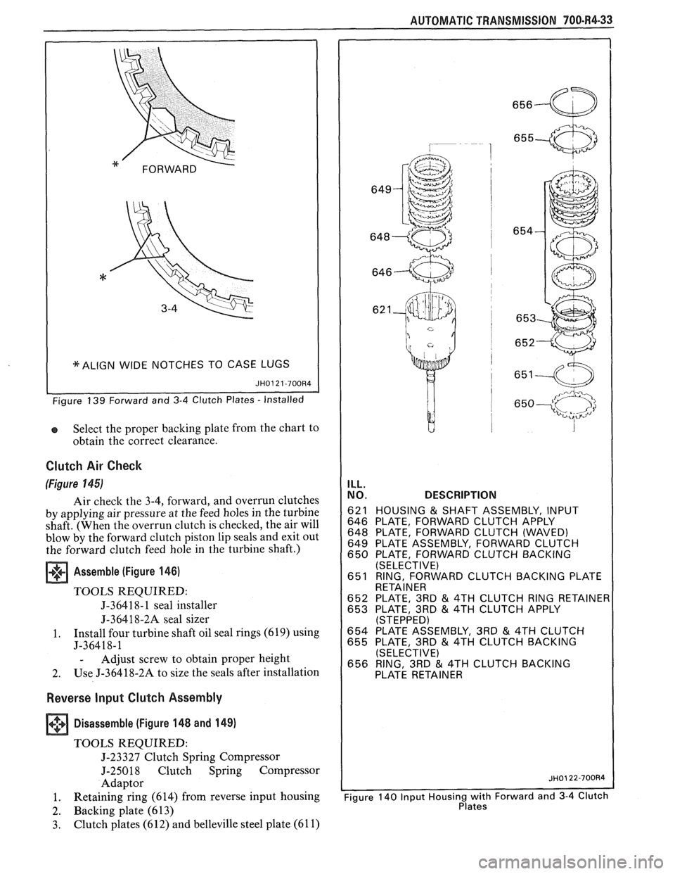
I *ALIGN WIDE NOTCHES TO CASE LUGS (
Select the proper backing plate from the chart to
obtain the correct clearance.
Clutch Air Check
(Figure 145)
Air check the 3-4, forward, and overrun clutches
by applying air pressure at the feed holes in the turbine
shaft. (When the overrun clutch is checked, the air will
blow by the forward clutch piston lip seals and exit out
the forward clutch feed hole in the turbine shaft.)
Assemble (Figure 146)
TOOLS REQUIRED:
J-36418- 1 seal installer
J-36418-2A seal sizer
1. Install four turbine
shaft oil seal rings (619) using
J-36418-1
- Adjust screw to obtain proper height
2. Use
J-36418-2A to size the seals after installation
Reverse Input Clutch Assembly
+++ Disassemble (Figure 148 and 149) [I]
TOOLS REQUIRED:
J-23327 Clutch Spring Compressor
J-25018 Clutch Spring Compressor
Adaptor
1. Retaining
ring (614) from reverse input housing
2. Backing plate (613)
3. Clutch plates (612) and belleville steel plate (61 1)
AUTOMATIC TRANSMISSION 700-R4-33
ILL.
NO. DESCRIPTION
621 HOUSING & SHAFT ASSEMBLY, INPUT
646 PLATE, FORWARD CLUTCH APPLY
648 PLATE, FORWARD CLUTCH (WAVED)
649 PLATE ASSEMBLY, FORWARD CLUTCH
650 PLATE, FORWARD CLUTCH BACKING
(SELECTIVE)
651 RING, FORWARD CLUTCH BACKING PLATE
RETAINER
652 PLATE, 3RD
& 4TH CLUTCH RING RETAINE 653 PLATE, 3RD & 4TH CLUTCH APPLY (STEPPED) 654 PLATE ASSEMBLY, 3RD & 4TH CLUTCH
655 PLATE, 3RD & 4TH CLUTCH BACKING
(SELECTIVE)
656 RING, 3RD
& 4TH CLUTCH BACKING
Page 1158 of 1825
CLUTCH 7C-4
SECTION 76
CLUTCH
CONTENTS
GENERAL DESCRIPTION .......................... .. ............................................................. 7C-I
DIAGNOSIS ...................................................................................................................... 7C-3
Preliminary Checks ....................... ... ............................................................................ 7C-2
Bleeding Hydraulic Clutch System ................... .. .......................................................... 7C-2
ON-VEHICLE SERVICE ................................................................................................. 7C-5
Clutch Hydraulic System ................................................................................................. 7C-5
..................... Pressure Plate and Disc .. ........................................................................... 7C-6
Clutch Pedal ..................................................................................................................... 7C-6
Pilot Bearing .................................................................................................................. 7C-6
....................................................................................................... SPECIFICATIONS 7C-8
............................................................................................................ SPECIAL TOOLS 7C-8
GENERAL DESCRIPTION
COMPONENTS
The principal parts of a clutch system are: the
driving member and the operating members. Figure
7C-1 shows an exploded view of the clutch system.
DRIVEN MEMBERS (FIGURES 7C-1 AND 7C-2)
The driven member is the clutch disc with a
splined hub which is free to slide lengthwise along the
splines of the input shaft, but which drives the input
shaft through these same splines.
The driving and driven members are held in
contact by spring pressure. This pressure is exerted by
a diaphragm spring in the pressure plate assembly.
HYDRAULIC CLUTCH (FIGURE 7C-3)
A hydraulic clutch operating mechanism is used
on all models. The
mechanism consist of a remote
reservoir, clutch master cylinder and slave cylinder.
The remote reservoir is mounted to a bracket which
bolts to the power brake booster. The clutch master
cylinder is mounted on the cowl panel and the slave
cylinder is mounted on the bell housing. The clutch
master cylinder is operated directly off the clutch
pedal.
When the clutch pedal is pressed down, hydraulic
fluid under pressure from the clutch master cylinder
flows into the slave cylinder. Since the piston is also
connected to the clutch fork this lever moves the
release bearing into contact with the clutch cover
release fingers to disengage the clutch. The hydraulic
clutch system locates the clutch pedal height and
provides automatic clutch adjustment. No adjustment
of clutch linkage or pedal position is required.
OPERATING MEMBERS (FIGURE 7C-3)
HYDRAULIC CLUTCH FLUID
When adding fluid to or refilling the system after
The clutch release system is operated by service operations use GM Delco Supreme No. 11 hydraulic pressure and consists of the clutch pedal, brake fluid or an equivalent fluid that meets DOT 3 clutch master cylinder, clutch slave cylinder, clutch specifications. fork and clutch release bearing.
NOTICE: Do not use mineral or paraffin base oil in
the Clutch Hydraulic System. These fluids will
damage the rubber parts in the cylinders.
Page 1682 of 1825
GENERAL INFORMATION - F STYLE 1 H-1
SECTION IH
GENERAL NFORMAT
NOTICE: The anti-theft label found on some major sheet metal, engines, and transmissions must be masked
prior to painting, rustproofing, undercoating, etc. The mask
must be removed following the above operations.
Failure to keep the label clean and readable may result in liability for violation of Federal Vehicle Theft Prevention
Standard, and subject the vehicle owner to possible suspicion that the part was stolen.
Lock Cylinder Coding
..................................... I H-1 Chip Resistant Plastisol Material .................... 1 H-8
...................................................... Lubrication 1 H-2 Flexible Exterior Plastic Parts ......................... 1H-9
Adhesive Body Side Moldings ......................... 1H-3 Metal Replacement Parts Finishing ................ lH-13
Waterleak Diagnosis and Repair ..................... 1H-3 Interior Plastic Trim Parts Finishing .............. 1H-13
.................................................... Anticorrosion Treatment ................................ IH-4 Special Tools I H- 14
LOCK CYL!NDER CODING o Check key operation in the lock cylinder.
KEY IDENTIFICATION AND USAGE
REPLACEMENT LOCK CYLINDERS
The lock cylinder keyway is designed so that
other model keys will not enter a current model lock
cylinder. Two noninterchangeable keys are used.
CB Square headed key is used in the ignition lock
cylinder.
o Oval headed key is used in all other lock
cylinders.
Key identification is obtained from the four
character key code stamped on the knockout portion
of the key head and an identification letter stamped on
the key shank. After the code number has been
recorded by the owner, the plugs should be knocked
out of the key head. From these numbers, the lock
combination can be determined by use of a code list
(available to owners of key cutting equipment from
equipment suppliers). If key code numbers are not
available from records or from the knockout plug, the
lock combination (tumbler numbers and position) can
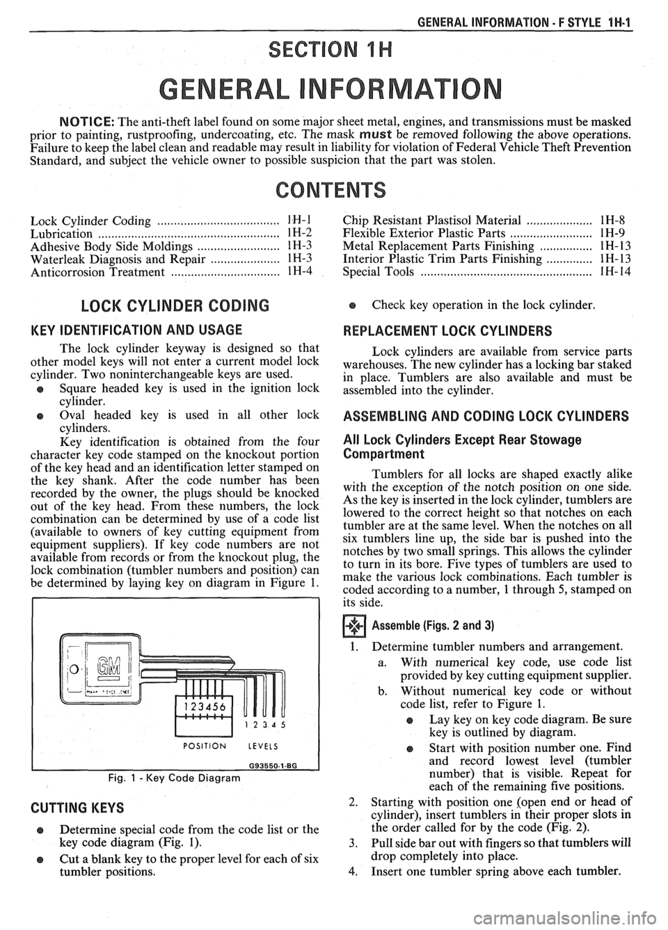
be determined by laying key on diagram in Figure
1.
I POSITION LEVELS I
Fig. 1 - Key Code Diagram
CUTTING KEYS
Lock cylinders are available from service parts
warehouses. The new cylinder has a locking bar staked
in place. Tumblers are also available and must be
assembled into the cylinder.
ASSEMBLING AND CODING LOCK CYLINDERS
All Lock Cylinders Except Rear Stowage
Compartment
Tumblers for all locks are shaped exactly alike
with the exception of the notch position on one side.
As the key is inserted in the lock cylinder, tumblers are
lowered to the correct height so that notches on each
tumbler are at the same level. When the notches on all
six tumblers line up, the side bar is pushed into the
notches by two small springs. This allows the cylinder
to turn in its bore. Five types of tumblers are used to
make the various lock combinations. Each tumbler is
coded according to a number,
1 through 5, stamped on
its side.
Assemble (Figs. 2 and 3)
1. Determine tumbler numbers and arrangement.
a. With numerical
key code, use code list
provided by key cutting equipment supplier.
b. Without numerical
key code or without
code list, refer to Figure
1.
o Lay key on key code diagram. Be sure
key is outlined by diagram.
Determine special code from the code list or the
key code diagram (Fig.
1). 3.
o Cut a blank key to the proper level for each of six
tumbler positions.
4.
Start with position number one. Find
and record lowest level (tumbler
number) that is visible. Repeat for
each of the remaining five positions.
Starting with position one [open end or head of
cylinder), insert tumblers in their proper slots in
the order called for by the code (Fig.
2).
Pull side bar out with fingers so that tumblers will
drop completely into place.
Insert one tumbler spring above each tumbler.
Page 1685 of 1825
1H-4 GENERAL INFORMATION - F STYLE
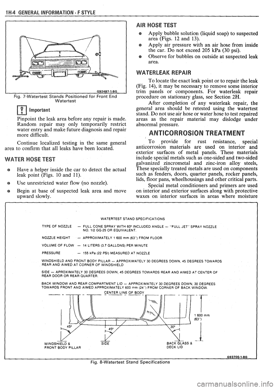
Fig. 7-Watertest Stands Positioned for Front End
Watertest
Important
Pinpoint the leak area before any repair is made.
Random repair may only temporarily restrict
water entry and make future diagnosis and repair
more difficult.
Continue localized testing in the same general
area to confirm that all leaks have been located.
WATER HOSE TEST
e Have a helper inside the car to detect the actual
leak point (Figs. 10 and 11).
Use unrestricted water flow (no nozzle).
Begin at base of suspected leak area and move
upward slowly.
AIR HOSE TEST
Apply bubble solution (liquid soap) to suspected
area (Figs. 12 and 13).
Apply air pressure with an air hose from inside
the car. Do not exceed 205
kPa (30 psi).
Observe for bubbles on outside at suspected leak
area.
WATERLEAK REPAIR
To locate the exact leak point or to repair the leak
(Fig.
14), it may be necessary to remove some interior
trim panels or components. For waterleak repair
procedure on stationary glass, see Section
2H.
After completion of any waterleak repair, the
general area should be retested using the watertest
stand. Do not use air hose or water hose to test repaired
areas as the repair material may dislodge under
abnormal pressure.
ANTICORROSION TREATMENT 1 To provide for rust resistance, special
anticorrosion materials are
used on interior and
exterior surfaces of metal panels. These materials
include special metals such as one-sided and two-sided
galvanized zincrometal and zinc-iron alloy steels,
These specially treated metals are used on components
such as fenders, doors, quarter panels, rocker panels,
lids, floor pans, wheelhousings and other critical parts.
Special metal conditioners and primers are used
on interior and exterior surfaces along with protective
waxes on interior surfaces in areas where moisture
WATERTEST STAND SPECIFICATIONS
TYPE OF NOULE
- FULL CONE SPRAY WITH 60' INCLUDED ANGLE - "FULL JET" SPRAY NOZZLE
NO. 112 GG-25 OR EQUIVALENT
NOULE HEIGHT - APPROXIMATELY 1 600 mrn (63") FROM FLOOR
VOLUME OF FLOW
- 14 LITERS (3.7 GALLONS) PER MINUTE
PRESSURE
- 755 kPa (22 PSI) MEASURED AT NOZZLE
WINDSHIELD AND FRONT BODY PILLAR
- APPROXIMATELY 30 DEGREES DOWN, 45 DEGREES TOWARDS
REAR AND AIMED AT CORNER OF WINDSHIELD
StDE - APROXIMATELY 30 DEGREES DOWN, 45 DEGREES TOWARDS REAR AND AIMED AT CENTER OF
REAR DOOR OR REAR QUARTER
BACK WINDOW AND REAR COMPARTMENT LID
- APPROXIMATELY 30 DEGREES DOWN. 30 DEGREES
TOWARDS FRONT AND AIMED APPROXIMATELY 600 rnm (24") FROM CORNER OF BACK WINDOW
CENTER
LINJ OF BODY - --
WINDSHIELD 8. SIDE BACK GLASS & FRONT BODY PILLAR DECK
LID
Fig. &Watertest Stand Specifications
Page 1686 of 1825
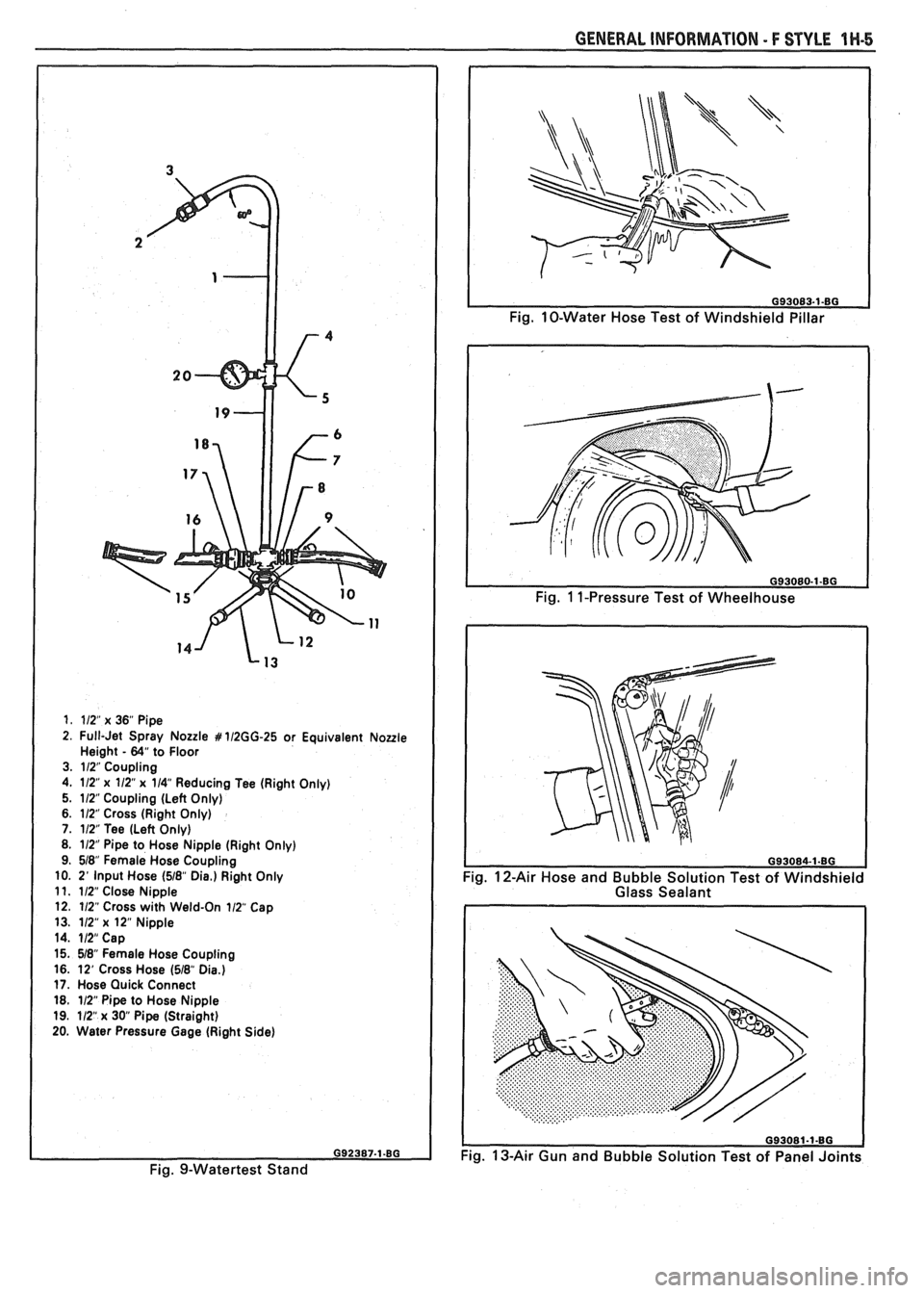
1. 112" x 36" Pipe
2. Full-Jet Spray Nozzle # 112GG-25 or Equivalent Noule Height - 64" to Floor
3. 112" Coupling
4. 112"
x 112" x 114" Reducing Tee (Right Only)
5. 112 Coupling (Left Only)
6. 112" Cross (Right Only)
7. 112" Tee (Left Only)
8. 112" Pipe to Hose Nipple (Right Only)
9. 518" Female Hose Coupling
10. 2'
Input Hose (518" Die.) Right Only
11. 112" Close Nipple
12. 112" Cross with Weld-On 112 Cap
13. 112"
x 12" Nipple
14. 112" Cap
15. 518" Female Hose Coupling
16. 12' Cross Hose
(518" Dia.) 17. Hose Quick Connect
18. 112" Pipe to Hose Nipple
19. 112"
x 30 Pipe (Straight)
20. Water Pressure Gage (Right Side)
Fig. 9-Watertest Stand
GENERAL INFORMATION - F STYLE 1 W-5
Fig. 10-Water Hose Test of Windshield Pillar
Fig.
1 1-Pressure Test of Wheelhouse
Fig. 12-Air Hose and Bubble Solution Test of Windshield
Glass Sealant
093081-1-80
Fig. 13-Air Gun and Bubble Solution Test of Panel Joints
Page 1746 of 1825
procedure or glass breakage and
personal injury could occur.
The compartment lift window assembly height,
fore and aft and side adjustments are controlled at the
hinge-to-body location. This area of the body has
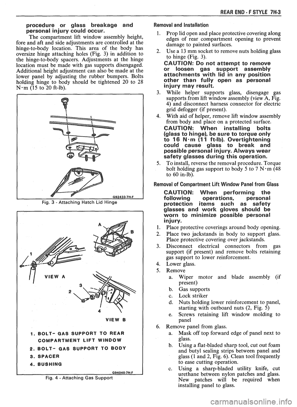
oversize hinge attaching holes (Fig. 3) in addition to
the hinge-to-body spacers. Adjustments at the hinge
location must be made with gas supports disengaged.
Additional height adjustment can also be made at the
lower panel by adjusting the rubber bumpers. Bolts
holding hinge to body should be tightened 20 to 28
N-m (15 to 20 ft-lb).
, ,' VIEW A
2
1. BOLT- GAS SUPPORT TO REAR
COMPARTMENT
LIFT WINDOW
2. BOLT- GAS SUPPORT
TO BODY
3. SPACER
4. BUSHING
Fig. 4 - Attaching Gas Support
REAR END - F STYLE 7W-3
Removal and Installation
1. Prop lid open and place protective covering along
edges of rear compartment opening to prevent
damage to painted surfaces.
2. Use
a 13 mm socket to remove nuts holding glass
to hinge (Fig. 3).
CAUTION: Do not attempt to remove
or loosen gas support assembly
attachments with lid in any position
other than fully open as personal
injury may result.
3. While helper supports glass, disengage gas
supports from lift window assembly (view A, Fig.
4) and disconnect harness connector for electric
grid defogger (if present).
4. With
aid of helper, remove lift window assembly
from body and place on a protected surface.
CAUTION: When installing bolts
(glass to hinge), be sure to torque only
to
16 N-m (1 1 ft-lb). Overtightening
could cause glass to break and
possible personal injury. Always wear
safety glasses during this operation.
5. To install, reverse the removal procedure. Torque
bolt holding gas support to body 5 to
7 N-m (48
to 60 in-lb).
Removal of Compartment Lift Window Panel from Glass
CAUTION: When performing the
following operations, personal
protection
iterns such as safety
glasses and work gloves should be
worn to minimize possible personal
injury.
1. Place protective coverings around body opening.
2. Place two jackstands in body to support glass.
Place protective covering over jackstands.
3. Disconnect electrical connectors from gas
support (if present) and remove bolts retaining
gas support to lower reinforcement.
4. Lower glass.
5. Remove a. Wiper motor and blade assembly (if
present)
b. Gas supports
c. Lock striker
d. Nuts
holding lower reinforcement to panel,
starting with outboard nuts
(2, Fig. 5)
e. Screws
retaining lift window molding to
panel
6. Remove panel from glass.
a. Mask
off top forward edge of panel next to
glass.
b. Using
a flat-bladed sharp tool, cut out foam
and butyl sealing strips between panel and
glass (1 and 2, Fig. 6). Clean tool frequently
to ease cutting operation.
c. Using a sharp-bladed utility knife, cut
urethane between nylon patches and glass.
New patches will be required when
installing panel to glass.