1988 PONTIAC FIERO height
[x] Cancel search: heightPage 151 of 1825
3A-4 WHEEL ALIGNMENT
AXLE HOUSING ALIGNMENT 2. If a tram is used for checking toe out, it will still
be necessary to perform Steps
1 and 2 in order to If rear tire wear indicates that the axle housing
check camber.
may be bent, the alignment can be checked as follows:
The necessary straightening operations may be
1. Back the car squarely onto an alignment performed using frame straightening equipment
machine, ~h~ actual toe-out will be read on the without removing the axle housing from the car. This
scale as toe-in. However, if the toe-out is checked procedure will allow checks during the straightening
with a tram gage, disregard this notice. operation
to determine when the housing is within the
prescribed limits.
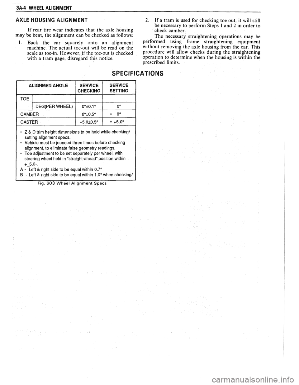
SPECIFICATIONS
1 CASTER 1 +5.0+0.5O 1 +5.0° 1
TOE
* Z & D trim height dimensions to be held while checking1
setting alignment specs.
* Vehicle must be jounced three times before checking
alignment, to eliminate false geometry readings.
Toe adjustment to be set separately per wheel, with
steering wheel held in "straight-ahead" position within
+-5.0-.
A - Left & right side to be equal within 0.7"
B - Left & right side to be equal within 1 .OO when checking1
Fig. 603 Wheel Alignment Specs
DEG(PER WHEEL)
CAMBER OO+O.10 0°
O0+O.5O A 0°
Page 188 of 1825
STEERING LINKAGE 3B6-1
SECTION 3B6
STEERING LINKAGE
The following notice applies to one or more steps in the assembly
procedure of components in this portion of the manual as Notice indicated at
appropriate locations by the terminology "See Caution on Page
1 of this
Section
" .
NOTICE: These fasteners are important attaching parts in that they
could affect the performance of vital components and systems,
andlor could
result in major repair expense. They must be replaced with one of the same
part number or with an equivalent part if replacement becomes necessary. Do
not use a replacement part of lesser quality or substitute design. Torque
values must be used as specified during reassembly to assure proper retention
of these parts. For prevailing torque
nut(s) and bolt(s), refer to the "Reuse of
Prevailing Torque
Nut(s) and Bolt(s)" chart in Section 10.
CONTENTS
General Description ........................................... 3B6- 1 Relay Rod ............................................................ 3B6-3
Maintenance and Adjustments ............................... 3B6- I Idler Arm ............................................................. 3B6-4
On-Car Service ........................................................ 3B6-2 Pitman Arm ......................................................... 3B6-5
Tie Rods .............................................................. 3B6-2 Specifications ........................................................... 3B6-6
GENERAL DESCRIPTION
A parallelogram type steering linkage connects both
steering gear. The right end of the relay rod is supported by
front wheels to the steering gear through the
pitman arm,
the idler arm which pivots on a support attached to the
The right and left tie rods are attached to the steering arms
frame rail. The
pitman arm and idler arm remain parallel to
and to the relay rod by ball studs. The left end of the relay
each other while they move through symmetrical arcs. See
rod is supported by the
pitman arm, which is driven by the Fig. 3B6-2.
MAONTENANCE AND ADJUSTMENTS
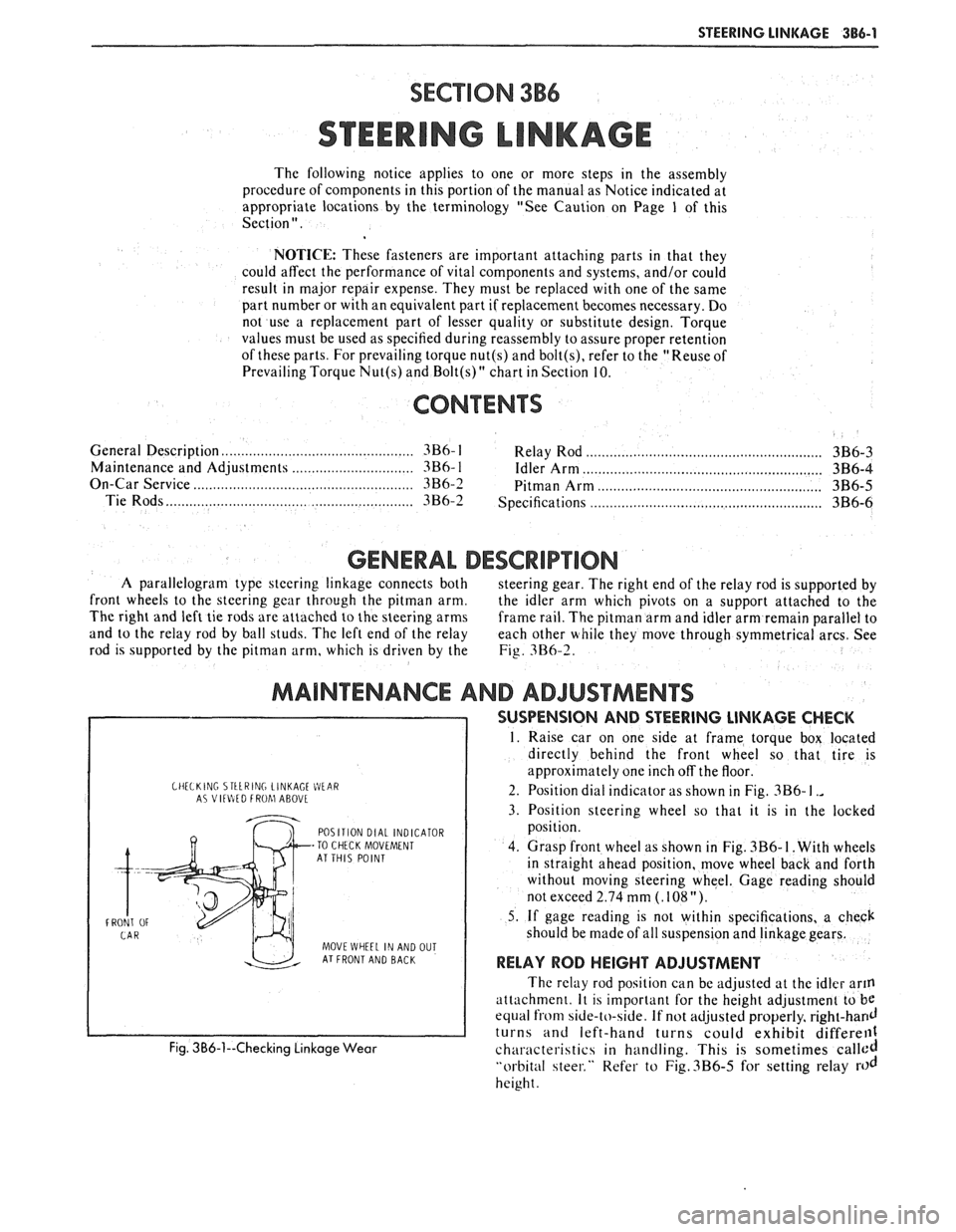
CHELKlNC STtLRING LINKAGE WEIR A? VltlItD FROhl ABOVL
POSITION DIAL INDICATOR
-TO CHECK MOVEMENT
AT THIS POINT
FRONT
OF
MOVE WHEEL IN AND OUT AT FRONT AND BACK
Fig. 3B6-1--Checking Linkage Wear
SUSPENSION AND STEERING LINKAGE CHECK
1. Raise car on one side at frame torque box located
directly behind the front wheel so that tire is
approximately one inch off the floor.
2. Position dial indicator as shown in Fig.
3B6- I .,
3. Position steering wheel so that it is in the locked
position.
4. Grasp front wheel as shown in Fig.
3B6- I. With wheels
in straight ahead position, move wheel back and forth
without moving steering wheel. Gage reading should
not exceed 2.74 mm
(. 108 ").
5. If gage reading is not within specifications, a check
should be made of all suspension and linkage gears.
RELAY ROD HEIGHT ADJUSTMENT
The relay rod position can be adjusted at the idler arm
attach men^. It is important for the height adjustment to be
equal from side-to-side. If not adjusted properly, right-hand
turns and left-hand turns could exhibit differell1
characteristics in handling. This is sometimes called
"orbital steer." Refer to Fig.3B6-5 for setting relay rod
height.
Page 190 of 1825
STEERING LINKAGE 386-3
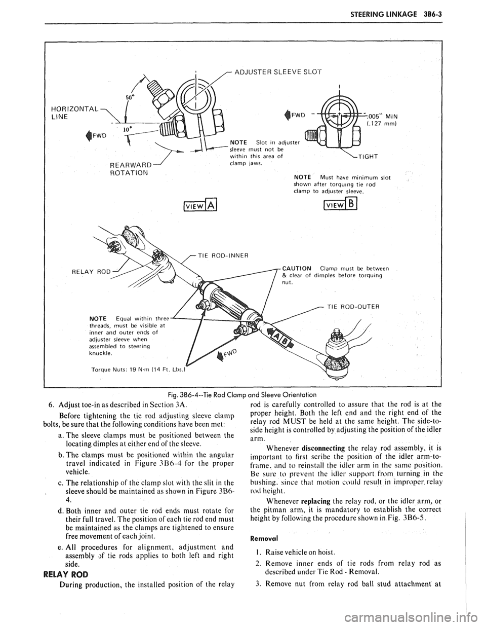
ADJUSTER SLEEVE SLOT
HORIZONTAL
NOTE Slot Iri adjuster
sleeve must not be
w~th~n th~q area of
clamp laws.
ROTATION NOTE Must have mlnlmum slot
shown after torqulng tie rod
TIE ROD-INNER
RELAY ROD
CAUTION Clamp must be between & clear of d~mples before torqulng
TIE ROD-OUTER
NOTE Equal w~th~n three
threads, must be vis~ble at Inner and outer ends of adjuster sleeve when
assembled to steerlng
Torque Nuts 19 N m (14 Ft Lbs
Fig. 3B6-4--Tie Rod Clamp and Sleeve Orientation
6. Adjust toe-in as described in Section
3A. rod is carefully controlled to assure that the rod is at the
Before tightening the tie rod adjusting sleeve clamp Proper height. Both the left end and the right end of the
bolts, be sure that the following conditions have been met: relay
rod MUST be held at the same height. The side-to-
side height is controlled by adjusting the position of the idler
a. The sleeve clamps must be positioned between the
arm. locating dimples at either end of the sleeve.
Whenever disconnecting the relay rod assembly, it is
b. The
clalnps must be positioned within the angular important to first scribe the position of the idler arm-to- travel indicated in Figure 3B6-4 for the Proper fi.ame. and to rein4tall the idler arm in the same position.
vehicle.
Be w1.e to prevent the idler support hom turning in the
c. The relationship of the clamp slot with the slit in the
bu4hing. since that motion could result in improper relay
sleeve should be maintained as shown in Figure
3B6- rod height.
4. Whenever replacing the relay rod, or the idler arm, or
d. Both inner and outer tie rod ends must rotate for the pitman arm, it is mandatory to establish the correct
their full travel. The position of each tie rod end must height
by following the procedure shown
in Fig. 3B6-5.
be maintained as the clamps are tightened to ensure
free movement of each joint.
Removal
e. All procedures for alignment, adjustment and
assembly
~f tie rods applies to both left and right I. Raise vehicle hoist.
side. 2. Remove inner ends of tie rods from relay rod as
RELAY ROD described under Tie Rod - Removal.
During production, the installed position of the relay
3. Remove nut from relay rod ball stud attachment at
Page 191 of 1825
386-4 STEERING LINKAGE
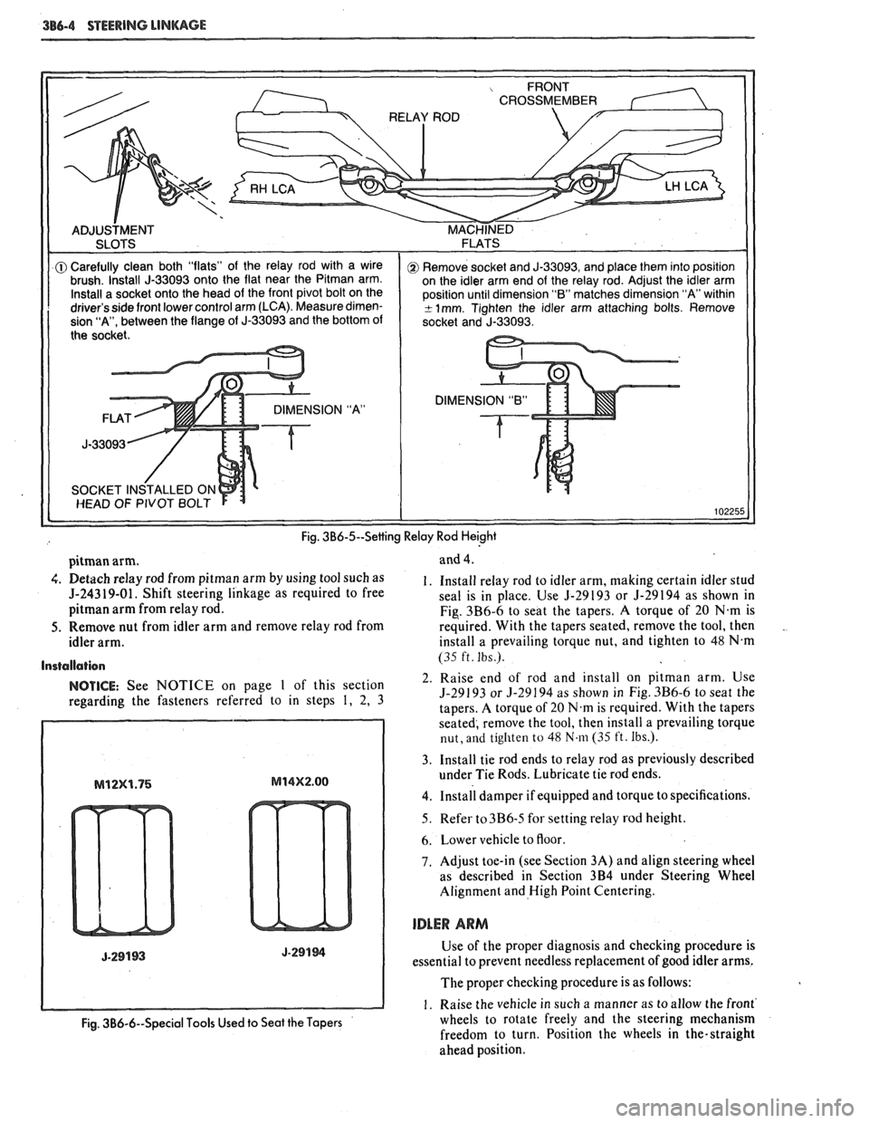
DIMENSION "B"
Fig. 3B6-5--Setting Relay Rod Heighi
pitman arm.
4. Detach relay rod from pitman arm by using tool such as
5-24319-01. Shift steering linkage as required to free
pitman arm from relay rod.
5. Remove nut from idler arm and remove relay rod from
idler arm.
Installation
NOTICE: See NOTICE on page 1 of this section
regarding the fasteners referred to in steps
1, 2, 3 and
4.
1. Install relay
rod to idler arm, making certain idler stud
seal is in place. Use
5-29193 or 5-29194 as shown in
Fig. 3B6-6 to seat the tapers. A torque of
20 N.m is
required. With the tapers seated, remove the tool, then
.
install a prevailing torque nut, and tighten to 48 N.m
(35 ft. Ibs.).
2. Raise end of rod and install on pitman arm. Use
5-29193 or 3-29194 as shown in Fig. 3B6-6 to seat the
tapers. A torque of
20 N.m is required. With the tapers
seated, remove the tool, then install a prevailing torque
nut, and tighten to 48 N.111 (35 ft. Ibs.).
3. Install tie rod ends to relay rod as previously described
under Tie Rods. Lubricate tie rod ends.
4. ~nstall damper if equipped and torque to specifications.
5. Refer to3B6-5 for setting relay rod height.
6. Lower vehicle to floor
7. Adjust toe-in (see Section 3A) and align steering wheel
as described in Section
3B4 under Steering Wheel
Alignment and High Point Centering.
IDLER ARM
Use of the proper diagnosis and checking procedure is
essential to prevent needless replacement of good idler arms.
The proper checking procedure is as follows:
1. Raise the vehicle in such a manner as to allow the front'
Fig. 3B6-6--Special Tools Used to Seat the Tapers wheels to rotate freely and the steering mechanism
freedom to turn. Position the wheels in the-straight
ahead position.
Page 192 of 1825
STEERING LINKAGE 386-5
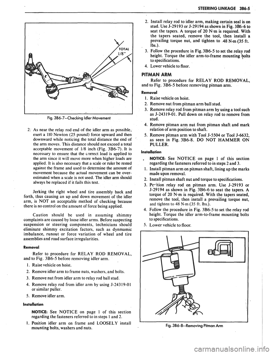
Fig. 3B6-7--Checking Idler Movement
2: As near the relay rod end of the idler arm as possible,
exert a 110 Newton
(25 pound) force upward and then
downward while noticing the total distance the end of '
the arm moves. This distance should not exceed a total
acceptable movement of
118 inch (Fig. 3B6-7). It is
necessary to ensure that the correct load is applied to
the arm since it will move more when higher loads are
applied. It is also necessary that a scale or ruler
be rested
against the frame and used to determine the amount of
movement because the actual movement can be over-
estimated when a scale is not used. The idler
arm should
always be replaced if it fails this test.
Jerking the right wheel and tire assembly back and
forth, thus causing an up and down movement of the idler
arm, is NOT an acceptable method of checking because
there is no control on the amount of force being applied.
Caution should be used in assuming shimmy
complaints are caused by loose idler arms. Before suspecting
suspension or steering components, technicians should
eliminate shimmy excitation factors, such as dynmamic
imbalance,
runout or force variation of wheel and tire
assemblies and road surface irregularities.
Removal
Refer to procedure for RELAY ROD REMOVAL,
and to Fig.
3B6-5 before removing idler arm.
1. Raise vehicle on hoist.
2. Remove idler arm to frame nuts, washers, and bolts.
3. Remove nut from idler arm to relay rod ball stud.
4. Remove relay rod from idler arm by using
5-24319-01
or similar puller.
5. Remove idler arm.
Installation
NOTICE: See NOTICE on page 1 of this section
regarding the fasteners referred to in steps
1 and 2.
I. Position idler arm on frame and LOOSELY install
mounting bolts, washers and nuts. 2.
Install relay rod to idler arm, making certain seal is on
stud. Use 5-29 193 or 5-29 194 as shown in Fig.
3B6-6 to
seat the tapers. A torque of 20
N.m is required. With
the tapers seated, remove the tool, then install a
prevailing torque nut, and tighten to
.48 N-m (35 ft.
Ibs.).
3. Follow the procedure in Fig. 3B6-5 to set the relay rod
height. Torque the idler arm-to-frame mounting
+Its
to specifications.
4. Lower vehicle to floor.
PITMAN ARM
Refer to procedure for RELAY ROD REMOVAL,
and to Fig.
3B6-5 before removing pitman arm.
Removal
1. Raise vehicle on hoist.
2. Remove nut from
pitman arm ball stud.
3. Remove relay rod from pitman arm by using a tool such
as
5-243 19-01. Pull down on relay rod to remove from
stud.
4. Remove pitman arm nut from pitman shaft and mark
relation of arm position to shaft.
5. Remove
pitman arm with Tool 5-5504 or Tool 5-6632,
as seen in Fig.
3B6-8. DO NOT HAMMER ON
PULLER.
Installation
. NOTICE: See NOTICE on page 1 of this section
regarding the fasteners referred to in steps 2 and
3.
1. Install pitman arm on pitman shaft, lining up the marks
made upon removal.
2. Install pitman shaft nut and torque to specifications.
3.
Pcrition relay rod on pitman arm. Use 5-29193 or
5-29194 as shown in Fig. 3B6-6 to seat the tapers. A
torque of 20
N.m is required. With the tapers seated,
remove the tool, then install a prevailing torque nut,
and tighten to 48 N.m (35 ft. Ibs.).
4. Follow the procedure in Fig.
3B6-5 to set the relay rod
height. Torque the idler arm-to-frame mounting bolts
to specifications.
5. Lower vehicle to floor.
Fig. 3B6-8--Removing Pitmon Arm I I
Page 218 of 1825
FRONT SUSPENSION 3C-7
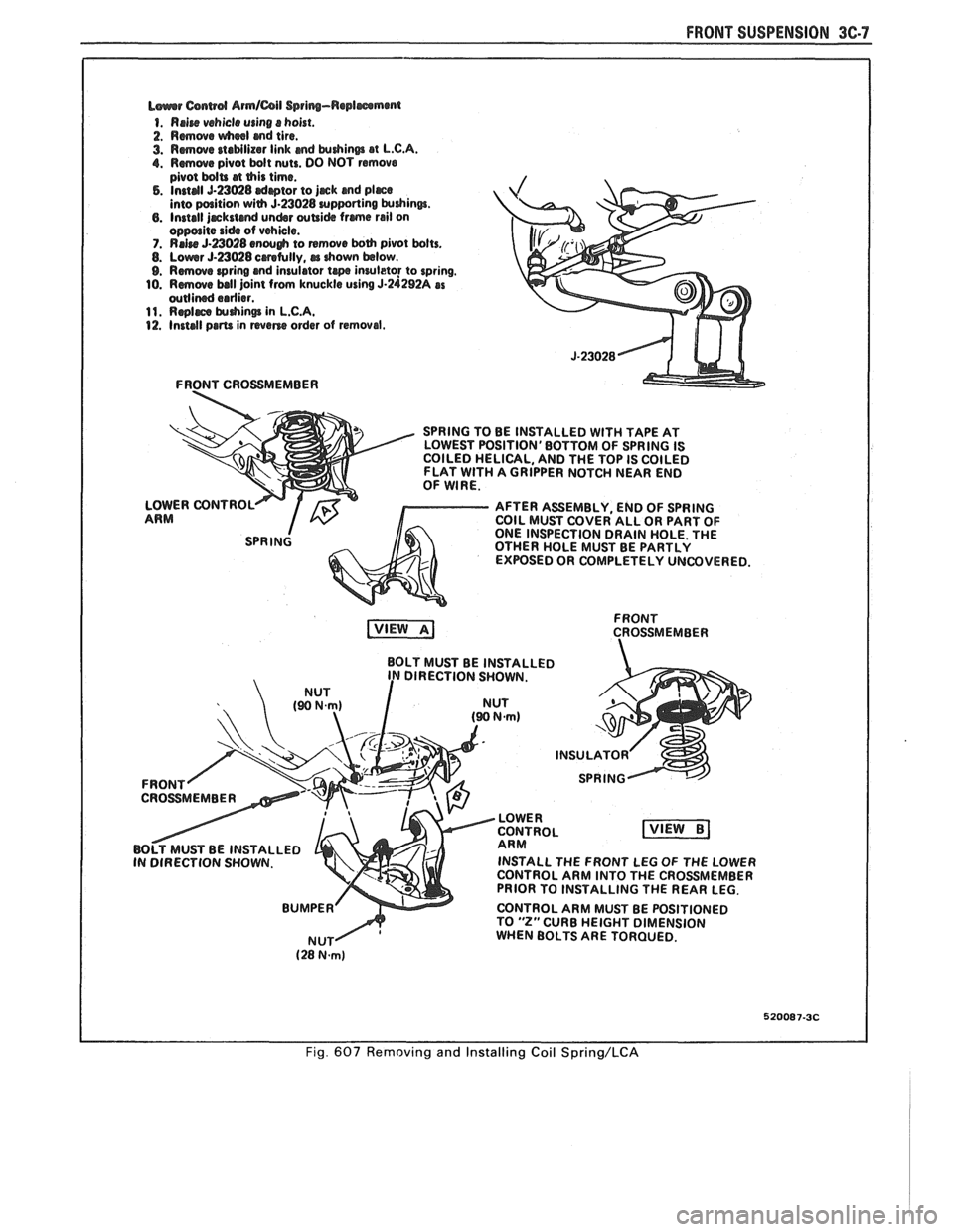
L~urrr Csnwd Armlail Spring-Replmmmt
1. Rrire vehicle using s hoist.
2. Rmwe wheel md tire.
3. Rmwe staMlizar link md krdrinm at L.C.A. 1. Rmwe pivot bdt nuts. DO NOT remove
pivot bdU at this time. 5. Instal 5-23028 drptor to jjrck and pljrce into paition with 5.23028 urpporting krdrinw. 6. Install jrckstcmd undsr wUi& frme rail on oppolite side of vehicle. 7. RrJre 5-a028 enough to remwe both pivot bolts. 8. Lowr 5-23028 crretully, rr drown below. 9. Rmove wring and insulator te inruleto! to spring.
10. Rmwe ball joint from knuckle using 5-24292A as wllined erdier. 11. Rqlrce $uhin@ in L.C.A. 12. Install prm in wane order of removal.
FRONT CROSSMEMBER
SPRING TO BE INSTALLED
WlTH TAPE AT
LOWEST POSITION'BOTTOM OF SPRING IS
COILED HELICAL, AND THE TOP IS COILED
FLAT
WlTH A GRIPPER NOTCH NEAR END
OF WIRE.
LOWER CONTROL
AFTER ASSEMBLY, END OF SPRING
ARM COIL MUST COVER ALL OR PART OF
ONE INSPECTION DRAIN HOLE. THE
OTHER HOLE MUST BE PARTLY
EXPOSED OR COMPLETELY UNCOVERED.
FRONT
CROSSMEMBER
BOLT MUST BE INSTALLED
DIRECTION SHOWN.
INSTALL THE FRONT LEG
OF THE LOWER
CONTROL ARM INTO THE CROSSMEMBER
PRIOR TO INSTALLING THE REAR LEG.
CONTROL ARM MUST BE POSITIONED
TO
"2" CURB HEIGHT DIMENSION
WHEN BOLTS ARE TORQUED.
520087-3C
Fig. 607 Removing and Installing Coil Spring/LCA
Page 224 of 1825
REAR SUSPENSION 30-3
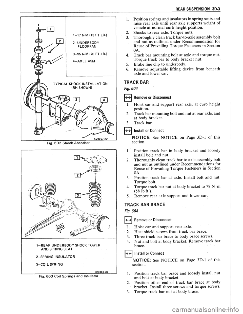
1. Position springs and insulators in spring seats and
raise rear axle until rear axle supports weight of
vehicle at normal curb height position.
2. Shocks to rear axle. Torque nuts. 1-17 N.M (13 FT.LB.1 3. Thoroughly clean track bar-to-axle assembly bolt
2-UNDERBODY and nut as outlined under Recommendation for
Reuse of Prevailing Torque Fasteners in Section
3-95 NeM (70 FT.LB.) 4. Track bar mounting bolt at axle and torque nut.
4-AXLE ASM. Torque track bar to body bracket nut.
5. Brake line clip to underbody.
6. Remove adjustable lifting device from beneath
axle and lower car.
TYPICAL SHOCK INSTALLATION TRACK BAR (RH SHOWN)
Remove or Disconnect
at body bracket.
3. Track bar.
Install or Connect
NOTICE: See NOTICE on Page 3D-1 of this
1. Position track bar in body bracket and loosely
install bolt and nut.
2. Thoroughly clean track bar to axle assembly bolt
and nut as outlined under Recommendations for
Reuse of Prevailing Torque Fasteners in Section
3. Position track bar at axle. Install bolt and nut.
4. Torque track bar nut at body bracket to 78 Nem
5. Remove rear axle support and lower car.
TRACK BAR BRACE
1. Hoist car and support rear axle.
2. Heat shield screws from track bar brace.
3. Three track bar brace to body brace screws.
4. Nut and bolt at body bracket. Remove track bar 1-REAR UNDERBODY SHOCK TOWER
AND SPRING SEAT.
2-SPRING INSULATOR
NOTICE: See NOTICE on Page 3D-1 of this 3-COIL SPRING
1. Position track bar brace and loosely install nut Fig. 603 Coil Springs and Insulator and bolt at body bracket.
2. Position other end of track bar brace at body
bracket. Install three screws and torque screws.
3. Torque track bar nut at body brace.
Page 225 of 1825
3D-4 REAR SUSPENSION
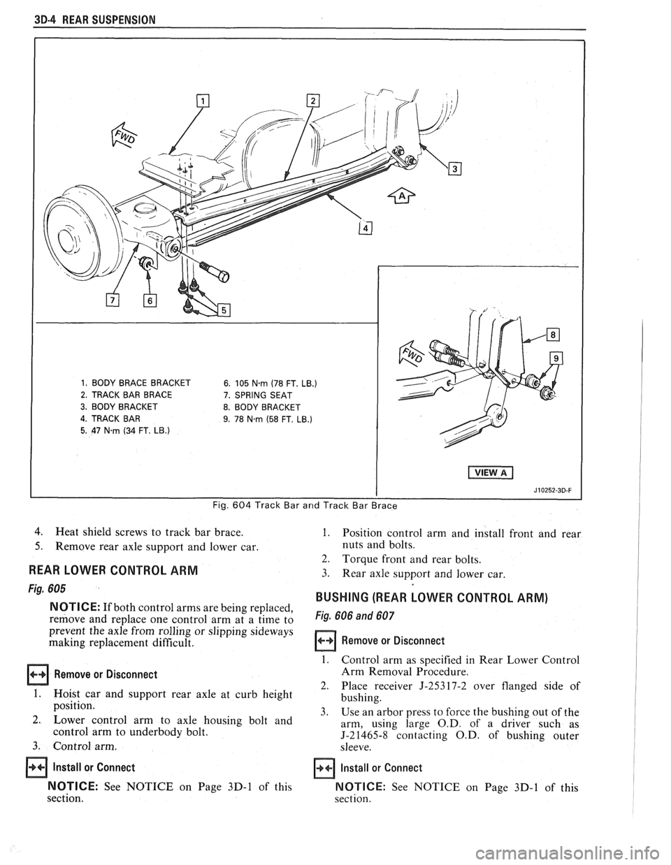
Fig. 604 Track Bar arrd Track Bar Brace
4. Heat shield screws to track bar brace.
5. Remove rear axle support and lower car.
REAR LOWER CONTROL ARM
Fig. 605
NOTICE: If both control arms are being replaced,
remove and replace one control arm at a time to
prevent the axle from rolling or slipping sideways
making replacement difficult.
Remove or Disconnect
1. Hoist car and support rear axle at curb height
position.
2. Lower control arm to axle housing bolt and
control arm to underbody bolt.
3. Control arm.
Install or Connect
NOTICE:
See NOTICE on Page 3D-1 of this
section.
1. Position control arm and install front and rear
nuts and bolts.
2. Torque front and rear bolts.
3. Rear axle support and lower car.
BUSHING (REAR LOWER CONTROL ARM)
Fig. 606 and 607
Remove or Disconnect
1. Control arm as specified in Rear Lower Control
Arm Removal Procedure.
2. Place receiver 5-25317-2 over flanged side of
bushing.
3. Use an arbor press to force the bushing out of the
arm, using large
O.D. of a driver such as
J-21465-8 contacting O.D. of bushing outer
sleeve.
Install or Connect
NOTICE:
See NOTICE on Page 3D-1 of this
section.