Page 820 of 1825
DRIVEABILITY AND EMISSIONS %.OL(VlN F) & 5.7L(VIN 8) 6E3-A-17
@ PROBE INJECTOR HARNESS
TERMINALS
WITH A TEST LlGHT TO
@ LIGHT SHOULD BE "ON" AT BOTH
DUE TO INJECTORS WIRED IN REPAIR
OPEN IN INJECTOR
PARALLEL, THERE SHOULD BE A
LIGHT ON BOTH TERMINALS.
Page 822 of 1825
: THIS CHART ASSUMES a CHART m THERE IS NO CODE 54
m PAGE 1.
THE IGNITION MA Y HA
VE TO BE CYCLED "ON"
RESSURE, WITH PUMP RUNNING SHOULD BE MORE
THAN ONCE TO OBTAIN MAXIMUM
(40.5-47 psi) AND HOLD STEADY WHEN PUMP PRESSURE.
ALSO, ITlS NORMAL FOR THE PRESSURE TO DROP SLIGHT1 Y WHEN THE PUMP STOPS.
10 SECONDS.
...... I
@ LEAKING PUMP
@ PLUGGED PUMP INLET FILTER.
RESTRICTED FUEL LINE.
Page 830 of 1825
DRIVEABILITY AND EMISSIONS 5.0L (WIN F) & 5.7L (WIN 8) 6E3-A-27
DIAGNOSTIC AID
COOLANT SENSOR
TEMPERATURE TO RESISTANCE VALUES
(APPROXIMATE)
CLEAR CODES AND CONFIRM "CLOSED LOOP" OPERATION AND NO "SERVICE ENGINE SOON" LIGHT.
Page 833 of 1825

6E3-A-30 5.OL (VIN F) & 5.7L (VIN 8) DRIVEABILITY AND EMISSIONS
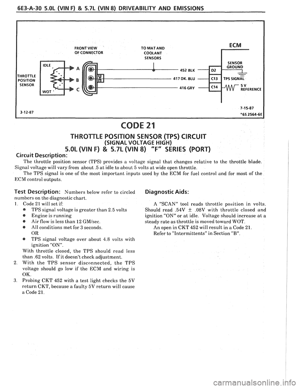
FRONT VIEW TO MAT AND
OF CONNECTOR
COOLANT
452
ELK D2
416 GRY - C14
CODE 21
THROmLE POSITION SENSOR (TPS) CIRCUIT
(SIGNAL VOLTAGE HIGH)
5.OL (VIN I") & 5.7L (VIN 8) 'T" SERIES (PORT)
Circuit Description:
The throttle position sensor (TPS) provides a voltage signal that changes relative to the throttle blade.
Signal voltage will vary from about
.5 at idle to about 5 volts at wide open throttle.
The TPS signal is one of the most important inputs used by the ECM for fuel control and for most of the
ECM control outputs.
Test Description: Numbers below refer to circled
numbers on the diagnostic chart.
1. Code 21 will set if:
@ TPS signal voltage is greater than 2.5 volts
@ Engine is running
@ Air flow is less than 12 GMIsec.
e All conditions met for 3 seconds.
OR
@ TPS signal voltage over about 4.8 volts with
ignition "ON".
With throttle closed, the TPS should read less
than .62 volts. If it doesn't check adjustment.
2. With the TPS sensor disconnected, the TPS
voltage should go low if the ECM and wiring is
OK.
Diagnostic Aids:
A "SCAN" tool reads throttle position in volts.
Should read
.54V f .08V with throttle closed and
ignition "ON" or at idle. Voltage should increase at a
steady rate as throttle is moved toward WOT.
An open in CKT 452 will result in
a Code 21.
Refer to "Intermittents" in Section
"B".
3. Probing CKT 452 with a test light checks the 5V
return CKT, because
a faulty 5V return will cause
a Code 21.
Page 834 of 1825
DRIVEABILITY AND EMISSIONS 5.OL (VIN F) & 5.7L (VIN 8) 6E3-A-31
DDlTlONAL CODES WERE STORED,
CLEAR CODES AND CONFIRM "CLOSED LOOP" OPERATION AND NO "SERVICE ENGINE SOON" LIGHT.
Page 842 of 1825
DRIVEABILITY AND EMISSIONS 5.OL (VIN F) & 5.7L (VIN 8) 6E3-A-39
MANIFOLD AIR TEMPERATURE (MAT)
IF NO ADDITIONAL CODES WERE
"SCAN" SHOULD DISPLAY TEMPERATURE
BELOW
-30°C.
DIAGNOSTIC AID
MAT SENSOR
TEMPERATURE TO RESISTANCE VALUES
(APPROXIMATE)
CLEAR CODES AND CONFIRM "CLOSED LOOP" OPERATION AND NO "SERVICE ENGINE SOON" LIGHT.
Page 843 of 1825

CODE 32
EXHAUST GAS RECBRCULATION (EGR) CIRCUIT
%.OL (VIN F) & 5.7L (VIN 8) "F" SERIES (PORT)
Circuit Description:
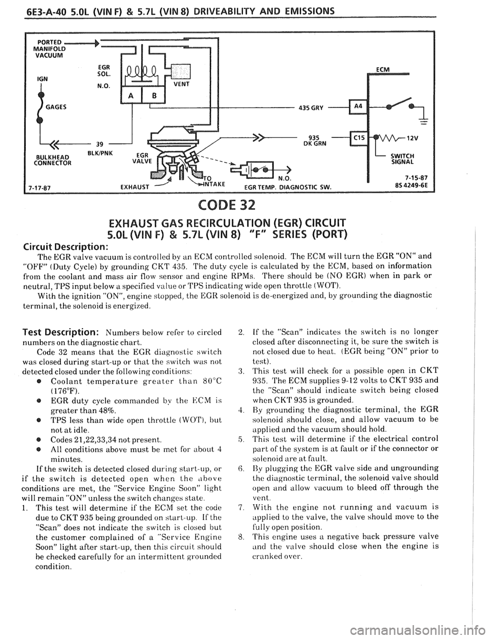
The EGR valve vacuum is controlled by an ECM controlled solenoid. 'I'he ECM will turn the EGR "ON" and
"OFF" (Duty Cycle) by grounding CKT 435. 'I'he duty cycle is calculated by the ECM, based on information
from the coolant and mass air flow sensor and engine
RPMs. 'I'here should be (NO EGR) when in park or
neutral,
TPS input below a specified value or TPS indicating wide open throttle (WOT).
With the ignition "ON", engine stopped, the EGR solenoid is de-energized and, by grounding the diagnostic
terminal, the solenoid is energized.
Test Description: Numbers below refer to circled
numbers on the diagnostic chart.
Code 32 means that the
EGR diagnostic switch
was closed during start-up or that the switch was not
detected closed under the following conclilions:
@ Coolant temperature greater than 80°C
( 176°F).
@ EGR duty cycle commanded by the ISCM is
greater than
48%.
@ TPS less than wide open throttle (WO'I'), but
not at idle.
@ Codes 21,22,33,34 not present.
@ All conditions above must be met for about 4
minutes.
If the switch is detected closed during start-up, or
if the switch is detected open when the
,lbove
conditions are met, the "Service Engine Soon" light
will remain
"ON" unless the switch changes state.
1. This test will determine if the ECM set the code
due to CKT 935 being grounded on start-up.
If the
"Scan" does not indicate the switch is closed but
the customer complained of a "Service Engine
Soon" light after start-up, then this circuit should
be checked carefully for an intermittent grounded
condition.
2. If the "Scan" indicates the switch is no longer
closed after disconnecting it, be sure the switch is
not closed due to heat.
(EGR being "ON" prior to
test).
3. 'I'his test will check for
u possible open in CKT
935. 'I'he EXM supplies 9-12 volts to CKrl' 935 and
the "Scan" should indicate switch being closed
when CK'P 935 is grounded.
4. By grounding the diagnostic terminal, the EGR
solenoid should close, and allow vacuum to be
applied and the vacuum should hold.
5. This test will determine if the electrical control
part of the system is at fault or if the connector or
solenoid are at fault.
6. I3y plugging the EGR valve side and ungrounding
the diagnostic terminal, the solenoid valve should
open and allow vacuum to bleed off through the
vent.
7. With the engine not running and vacuum is
applied to the valve, the valve should
move to the
fully open position.
8. 'I'his engine uses a negative back pressure valve
and the valve should close when the engine is
cranked over.
Page 844 of 1825
DRIVEABILITY AND EMISSIONS 5.OL (WIN F) & 5.7L (VIN 8) 6E3-A-41
- -- - - @ BEFORE USING THIS CHART, CHECK VACUUM HOSES
FOR LEAKS, RESTRICTIONS, AND CHECK PORTED
VACUUM SOURCE TO EGR SOLENOID; SHOULD HAVE
AT LEAST
7" Hg VACUUM (23.7 kPa) AT 2000 RPM. @ USING A "SCAN" TOOL, CHECK EGR DIAGNOSTIC
SWITCH INPUT.
DOES "SCAN" INDICATE SWITCH
IS CLOSED?
EXHAUST GAS RECIRCULATION
(EGR) CIRCUIT
5.0L (VIM F) & 5.7L (VIN 8)
"F" "SERIES (PORT)
@ DISCONNECT EGR TEMP. DIAGNOSTIC SWITCH. @ JUMPER HARNESS TERMINAL TO GND. @ DOES "SCAN" INDICATE SWITCH IS CLOSED?
@ DISCONNECT EGR TEMP. DIAGNOSTIC
SWITCH CONNECTOR.
@ DOES "SCAN" INDICATE SWITCH IS CLOSED?
UNABLE TO GET 10" VACUUM
ABLE TO GET 10" VACUUM
.
@ DISCONNECT EGR SOLENOID. @ PLUG EGR SIDE OF SOLENOID. @ CONNECT TEST LIGHT BETWEEN @ UNGROUND DIAGNOSTIC TERMINAL.
HARNESS CONNECTOR TERMS. NOTE
VACUUM (SHOULD BLEED OFF 1.
EGR DIAPHRAGM WHILE
CONNECTED TO
SHOULD MOVE
HOLD VACUUM
T
20 SECONDS.
IS GOOD IF DIAPHRAGM
HAS MOVED TO SEATED