1988 PONTIAC FIERO light
[x] Cancel search: lightPage 750 of 1825
DRIVEABILITY AND EMISSIONS 2.8L (VIN S) 6E3-CZ-15
NOTICE: Before instal ling new idle air control valve
assembly, the position of its pintle
MUST
be checked. If pintle is extended too far,
damage to the assembly may occur.
Measure
@ Distance from gasket mounting surface of IAC
valve assembly
(70) to tip of pintle, Dimension
"A" in Figure
C2-19.
Adjust
If distance is greater that 28 mm (1 118 in.), reduce -
it as follows:
a. If
IAC valve assembly has
a "collar" around
electrical connector end, use firm hand pressure
on pintle to retract it. (A slight side-to-side motion
may help.)
b. If IAC valve assembly has "no collar", compress
pintle-retaining spring toward body of the IAC
and try to turn pintle clockwise.
@ If pintle will turn, continue turning until
28mm
(1 118 in.) is reached. Return spring to
original position, with straight part of spring
end lined up with flat surface under the pintle
head.
@ If pintle will not turn, use firm hand pressure
to retract it.
Install or Connect
1. New IAC valve assembly gasket (71) on IAC valve
assembly
(70).
2. IAC valve assembly in idle airlvacuum signal
housing assembly
(60).
Tighten
IAC valve assembly to 18N.m (13 ft. Ibs.), with
wrench on hex surface only.
3. Electrical connector at IAC valve assembly (70).
Important
No physical adjustment is made to the IAC
assembly after installation.
IAC resetting occurs
after reinstallation on the vehicle, and is reset
after the engine is started and then the ignition
turned off.
IDLE AIR / VACUUM SIGNAL HOUSING
ASSEMBLY
(With
IAC Removed) (Figure C2-20)
Remove or Disconnect
1. Idle airlvacuurn signal assembly attaching screw
assemblies
(65) and (66).
2. Idle airlvacuum signal housing assembly (60).
3. Idle airlvacuum signal assembly gasket (67).
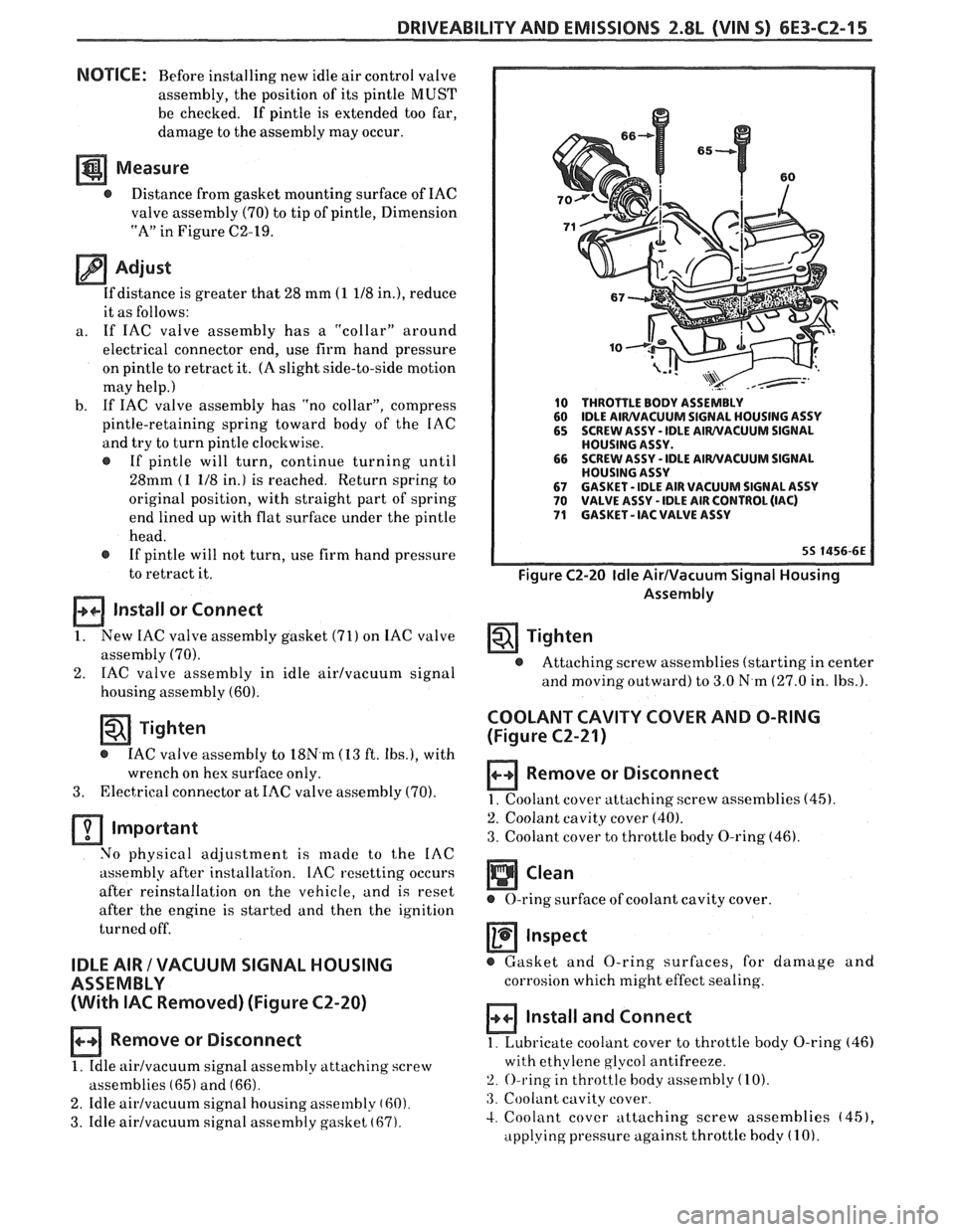
10 THROTTLE BODY ASSEMBLY
60 IDLE AIWVACUUM SIGNAL
HOUSING ASSY
65 SCREW ASSY - IDLE AIWVACUUM SIGNAL
HOUSING ASSY.
66 SCREW
ASSY
- IDLE AIWVACUUM SIGNAL
HOUSING ASSY
67 GASKET - IDLE AIR VACUUM SIGNAL ASSY 70 VALVE ASSY - IDLE AIR CONTROL (IAC) 71 GASKET - IAC VALVE ASSY
Figure C2-20 Idle AirIVacuum Signal Housing
Assembly
Tighten
@ Attaching screw assemblies (starting in center
and
moving outward) to 3.0 N.m (27.0 in. Ibs.).
COOLANT CAVITY COVER AND O-RING
(Figure
C2-21)
Remove or Disconnect
1. Coolant cover attaching. screw assemblies (45).
2. Coolant cavity cover (40).
3. Coolant cover to throttle body O-ring (46).
Inspect
@ Gasket and O-ring surfaces, for damage and
corrosion which might effect sealing.
Install and Connect
1. Lubricate coolant cover to throttle body O-ring (46)
with ethylene glycol antifreeze.
2. O-ring in throttle body assembly (10).
:3. Coolant cavity cover.
4. Coolant cover attaching screw assemblies (451,
applying pressure against throttle body (1 0).
Page 753 of 1825
6E3-C2-18 2.8L (VIN S) DRIVEABILITY AND EMISSIONS
CHART C-2A
INJECTOR BALANCE TEST
The injector balance tester is a tool used to turn the injector on for a precise
amount of time, thus spraying a measured amount of fuel into the manifold.
This causes a drop in fuel rail pressure that we can record and compare between
each injector. All injectors should have the same amount of pressure drop
( k 10
kpa). Any injector with a pressure drop that is 10 kpa (or more) greater or less
than the average drop of the other injectors should be considered faulty and
replaced.
Engine "cool down" period
(10 minutes) is necessary to avoid irregular
readings due to "Hot Soak" fuel boiling. With ignition
"OFF" connect fuel gauge
5347301 or equivalent to fuel pressure tap. Wrap a shop towel around fitting
while connecting gage to avoid fuel spillage.
Disconnect harness connectors at all injectors, and connect injector tester
J-
34730-3, or equivalent, to one injector. On Turbo equipped engines, use adaptor
harness furnished with injector tester to energize injectors that are not
accessible. Follow manufacturers instructions for use of adaptor harness.
Ignition must be
"OFF" at least 10 seconds to complete ECM shutdown cycle.
Fuel pump should run about
2 seconds after ignition is turned "ON". At this
point, insert clear tubing attached to vent valve into a suitable container and
bleed air from gauge and hose to insure accurate gauge operation. Repeat this
step until all air is bled from gauge.
STEP 2
Turn ignition "OFF" for 10 seconds and then "ON" again to get fuel pressure
to its maximum. Record this initial pressure reading. Energize tester one time
and note pressure drop at its lowest point (Disregard any slight pressure
increase after drop hits low point.). By subtracting this second pressure reading
from the initial pressure, we have the actual amount of injector pressure drop.
STEP 3
Repeat step 2 on each injector and compare the amount of drop. Usually, good
injectors will have virtually the same drop. Retest any injector that has
a
pressure difference of lOkPa, either more or less than the average of the other
injectors on the engine. Replace any injector that also fails the retest. If the
pressure drop of all injectors is within
lOkPa of this average, the injectors
appear to be flowing properly. Reconnect
them and review "Symptoms," Section
"B".
NOTE: The entire test should not be repeated more than once without
running the engine to prevent flooding. (This includes any retest on
fa ulty injectors).
Page 755 of 1825
6E3-C2-20 2.8L (VIN S) DRIVEABILITY AND EMISSIONS
AIR THROTTLE FLOW BODY
LD START VALVE
8-5 BLUNVHT
BLUIBLK
GRMNVHT
. GRNIBLK
ECM
.
IAC COIL
"A" HI
IAC COIL "A" LO
IAC COIL "B" HI
C3 IAC COIL "B" LO
7-1 6-87
55 1800-6E
CHART C-2C
IDLE AIR CONTROL
2.8L (VIN S) ""F-SERIES (PORT)
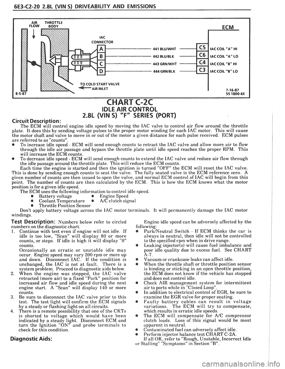
Circuit Description:
The ECM will control engine idle speed by moving the IAC valve to control air flow around the throttle
plate. It does this by sending voltage pulses to the proper motor winding for each IAC motor. This will cause
the motor shaft and valve to move in or out of the motor a given distance for each pulse received. ECM pulses
are referred to as "counts".
@ To increase idle speed - ECM will send enough counts to retract the IAC valve and allow more air to flow
through the idle air passage and bypass the throttle plate until idle speed reaches the proper RPM. This
will increase the ECM counts.
@ To decrease idle speed - ECM will send enough counts to extend the IAC valve and reduce air flow through
the idle passage around the throttle plate. This will reduce the ECM counts.
Each time the engine is started and then the ignition is turned "OFF" the ECM will reset the IAC valve.
This is done by sending enough counts to seat the valve. The fully seated valve is the ECM reference zero. A
given number of counts are then issued to open the valve, and normal ECM control of IAC will begin from this
point. The
number of counts are then calculated by the ECM. This is how the ECM knows what the motor
position is for
a given idle speed.
The ECM uses the following information to control idle speed.
@ Battery voltage @ Engine Speed
@ Coolant Temperature @ A/C clutch signal
@ Throttle Position Sensor
Don't apply battery voltage across the IAC motor terminals. It will permanently damage the IAC motor
windings.
Test Description: Numbers below refer to circled Engine
idle speed can be adversely affected by the
numbers on the diagnostic chart. following:
1. Continue
with test even if engine will not idle. If @ ParUNeutral Switch - If ECM thinks the car is
idle is too low, "Scan" will display
80 or more always
in neutral, then idle will not be controlled
counts, or steps. If idle is high it will display
"0" to the specified rpm when in drive range.
counts.
@ Leaking injector(s) will cause fuel imbalance and
Occasionally an erratic or unstable idle may poor
idle quality due to excess fuel. See CHART
occur. Engine speed may vary
200 rpm or more up A-7.
and down. Disconnect
EAC. If the condition is @ Vacuum or crankcase leaks can affect idle.
unchanged, the IAC is not at fault. There is
a @ When the throttle shaft or throttle position sensor
system problem. Proceed to diagnostic aids below. is
binding or sticking in an open throttle position,
2. When the engine was stopped, the IAC valve the
ECM does not know if the vehicle has stopped
retracted (more air) to a fixed "Park" position for and does not control idle.
increased air flow and idle speed during the next
@ Check AIR management system for intermittent
engine start. A "Scan" will display
140 or more air
to ports while in "Closed Loop".
counts. @ In addition to electrical control of EGR, be sure to
3. Be sure to disconnect the IAC valve prior to this examine the
EGR valve for proper seating.
test. The test light will confirm the ECM signals @ Faulty battery cables can result in voltage
by a steady or flashing light on all circuits. variations. The
ECM will try to compensate,
4. There is a remote possibility that one of the CKTs which results in erratic idle speeds.
is shorted to voltage which would have been @ The ECM will compensate for A/C compressor
indicated by a steady light. Disconnect ECM and clutch
loads. Loss of this signal would be most
turn the Ignition "ON" and probe terminals to apparent
in neutral.
check for this condition.
@ Contaminated fuel can adversely affect idle. @ Perform in
or Stalling" "Svmptoms" in Section "B".
Page 762 of 1825
DRIVEABILITY AND EMISSIONS f.8L (VIN 5) 6E3-C3-5
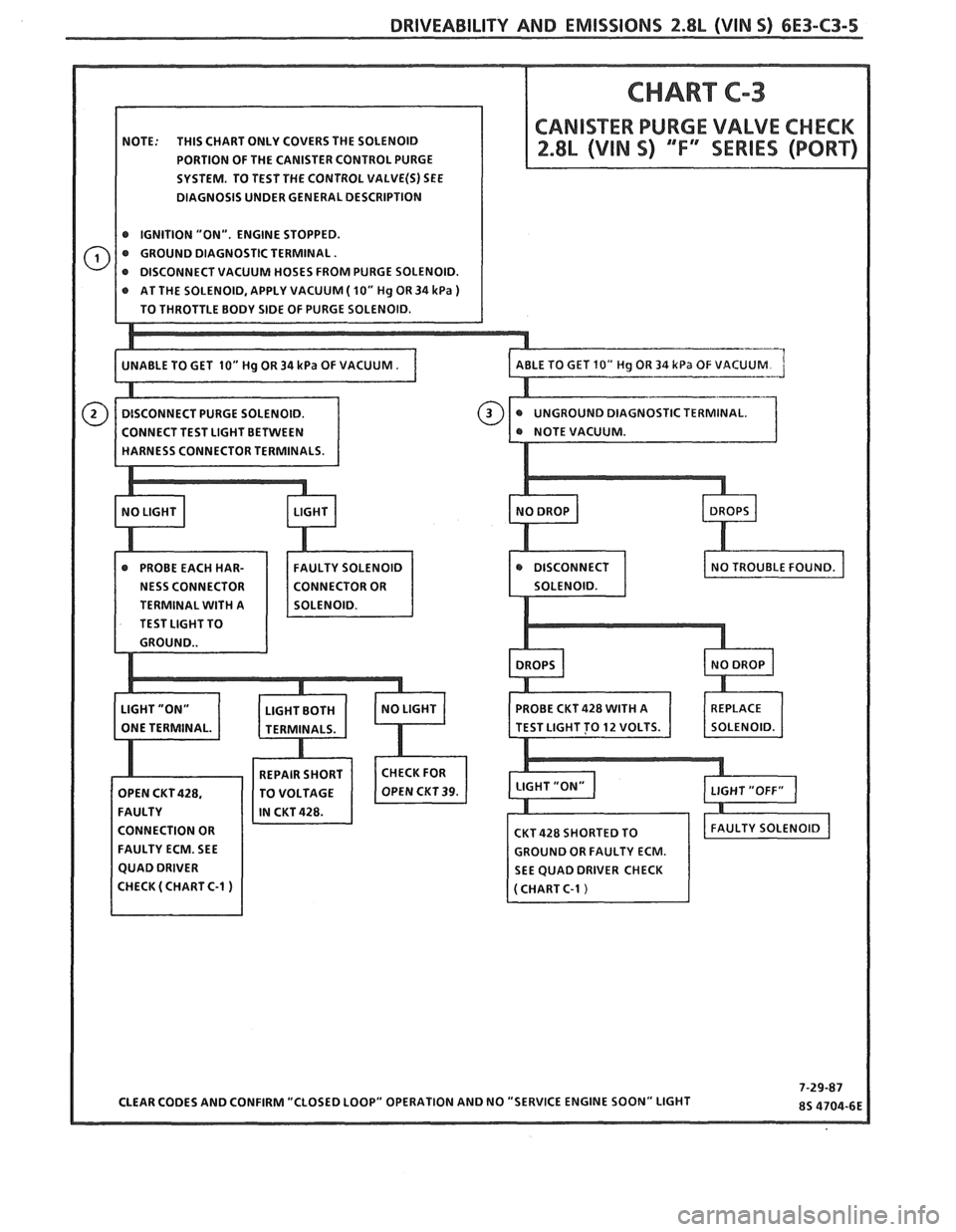
NOTE: THIS CHART ONLY COVERS THE SOLENOID
PORTION OF THE CANISTER CONTROL PURGE
SYSTEM. TO TEST THE CONTROL
VALVE(S) SEE
DIAGNOSIS UNDER GENERAL DESCRIPTION
@ IGNITION "ON". ENGINE STOPPED.
@ GROUND DIAGNOSTIC TERMINAL.
AT THE SOLENOID, APPLY VACUUM
( 10" Hg OR 34 kPa )
STIC TERMINAL.
TERMINAL
WITH A
TEST LIGHT TO
CONNECTION OR
FAULTY ECM. SEE
GROUND OR FAULTY ECM.
SEE QUAD DRIVER CHECK
Page 767 of 1825
6E3-C4-4 2.8L (VIN S) DRIVEABILITY AND EMISSIONS
430 PPLMlHT - 85 - REFERENCE
424
TANIBLK
453 BLWRED
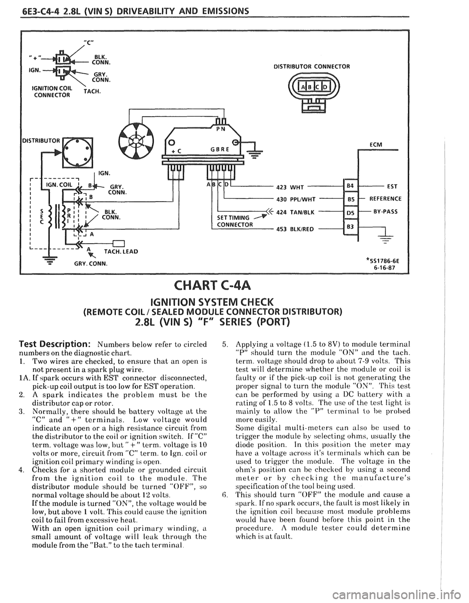
CHART C-4A
IGNITION SYSTEM CHECK
(REMOTE COIL / SEALED MODULE CONNECTOR DISTRIBUTOR)
2.8L (VIN 5) "F" SERIES (PORT)
Test Description: Numbers below refer to circled
numbers on the diagnostic chart.
1. Two wires are checked, to ensure that an open is
not present in
a spark plug wire.
1A. If spark occurs with EST connector disconnected,
pick-up coil output is too low for
EST operation.
2. A spark indicates the problem must be the
distributor cap or rotor.
3. Normally, there should he battery voltage at the
"C" and "+" terminals. Low voltage would
indicktte an open or a high resistance circuit from
the distributor to the coil or ignition switch. If
"C"
term. voltage was low, but " +" term. voltage is 10
volts or more, circuit from "C" term. to Ign. coil or
ignition coil primary winding is open.
4. Checks for a shorted module or grounded circuit
from the ignition coil to the module. The
distributor
nodule should be turned "OFF", so
normal voltage should be about
1% volts.
If the module is turned "ON", the voltage would be
low, but above
1 volt. 'I'his could cause the ig~lition
coil to fail from excessive heat.
With an open ignition coil primary
winding, i~
small amount of voltage will leak through the
module from the "Rat." to the tach terminal.
5. Applying a voltage (1.5 to 8V) to module terminal
"P" should turn the nlodule "ON" and the tach.
term. voltage should drop to about
7-9 volts. This
test will determine whether the module or coil is
faulty or if the pick-up coil is not generating the
proper signal to turn the
rnodule "ON". 'Phis test
can be performed by using a I)C battery with a
rating of
1.5 to 8 volts. The i~sc of the test light is
mainly to allow the
"P" terminal to be probed
more easily.
Some digital multi-meters can also be used t,o
trigger the module by selecting ohms, i~sually the
diode position. In this position the meter
may
have a voltage across it's terminals which can be
used to trigger the module.
'I'he voltage in the
ohm's position can be checked by
using a second
meter or by checking the manufacture's
specification of the tool being used.
6. This should turn "OFF" the nlodule and cause a
spark. If no
spark occurs, the fault is most likely in
the ignition coil because most module problems
would have been found before this point in the
procedure.
A moclule tester could determine
which is at fault.
Page 772 of 1825
DRIVEABILITY AND EMISSIONS 2.8L (WIN 5) 6E3-C6-3
4. If a leak is suspected on the pressure side of the
system or if
a hose or pipe has been disconnected
on the pressure side, the connections should be
checked for leaks with a soapy water solution.
With the pump running, bubbles will form if
a
leak exists.
Deceleration Valve
1. Connect tachometer, start engine and allow idle to
stabilize.
2. With the engine running at specified idle speed,
remove the small deceleration valve signal hose
from the manifold vacuum source.
3. Reconnect the signal hose and listen for air flow
through the ventilation pipe and into the
deceleration valve. There should also be a
noticeable speed drop when the signal hose is
reconnected.
4. If the air flow does not continue for at least one
second or the engine speed does not drop
noticeably, check the deceleration valve hoses for
restrictions or leaks.
5. If no restrictions or leaks are found, replace the
deceleration valve.
Check Valve
Inspect
1. A check valve should be inspected whenever the
hose is disconnected form
a check valve or
whenever check valve failure is suspected.
(A
pump that had become inoperative and had shown
indications of having exhaust gases in the pump
would indicate check valve failure).
2. Blow through the check valve (toward the exhaust
manifold) then attempt to suck back through the
check valve. Flow should only be in one
direction(towax-d the exhaust manifold). Replace
valve which does not operate properly.
ON-CAR SERVICE
DRIVE BELT
Remove or Disconnect
1. Inspect drive belt for ware, cracks or deterioration
and replace if required. When installing new belt,
it must be seated and fully secured in grooves of
A/C compressor, AIR pump, generator, and
crankshaft pulleys.
A.I.R. PUMP
Remove or Disconnect
1. Hold pump pulley from turning by compressing
drive belt, then loosen pump pulley bolts.
2. Loosen bolt, holding pump to mounting brackets,
release tension on drive belts.
3. Move belts out of the way, then remove pump
hoses, vacuum and electrical connections, and
control valve.
4. Pulley, then pump.
5. If required, insert needle nose pliers and pull filter
fan from hub.
Install or Connect
1. Air pump assembly, and tighten mounting bolts.
2. I-loses, vacuum and electrical connections, and
control valve
3. New
filter
fan on pump hub.
4. Spacer and pump pulley against centrifugal filter
fan.
5. Pump pulley bolts and tighten equally to 13 N m
(10 lb.
ft.). This will compress the centrifugal
filter fan onto the pump hole. Do not drive filter
fan on with a hammer. A slight amount of
interference with the housing bore is normal.
After a new filter fan has been installed, it
ma?;
squeal upon initial operation or until 0.11, sealing
lip has worn in. This
may require a short period of
purnp operation at various engine speeds.
6. Pump drive belt and adjust.
a Lon 7. Check air injection system for proper oper t'
(see CHART C-6)
AIR CONTROL VALVE
Remove or Disconnect
1. Battery ground cable.
2. Adapter bolts (See Figure C6-3).
3. Air outlet hoses from valve.
4. Adapter.
5. Electrical connectors and vacuum hoses from
valve. ve.
6. Control
va 1
Install or Connect
1. Control valve.
2. Electrical connectors and vacuum hoses.
3. Adapter.
4. Air hoses to valve.
5. Adapter bolts to pump.
6 Batterv ground crtble.
7. Check system operation (see CHART C-6)
Page 775 of 1825
6E3-C6-6 2.8L (VIN S) DRlVEABlLlTY AND EMISSIONS
AIR SOLENOID
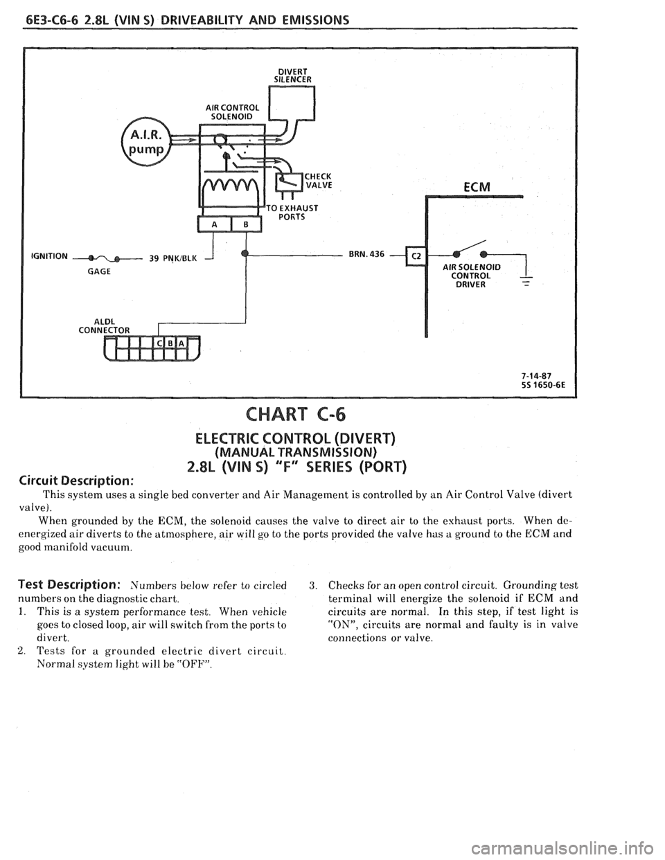
CHART C-6
ELECTRIC CONTROL (DIVERT)
(MANUAL TRANSMISSION)
2.8L (VIN S) "'F" SERIES (PORT)
Circuit Description:
This system uses a single bed converter and Air Management is controlled by an Air Control Valve (divert
valve).
When grounded by the ECM, the solenoid causes the valve to direct air to the exhaust ports. When
dc-
energized air diverts to the atmosphere, air will go to the ports provided the valve has a ground to the ECM and
good manifold vacuum.
Test Description: Numbers below refer to circled 3. Checks for an open control circuit. Grounding test
numbers on the diagnostic chart. terminal will energize the solenoid if ECM and
1. This is a system performance test. When vehicle circuits are normal. In this step, if test light is
goes to closed loop, air will switch from the ports to "ON", circuits are normal and faulty is in valve
divert. connections or valve.
2. 'rests for a grounded electric divert circuit.
Normal system light will be
"OFF".
Page 778 of 1825
DRIVEABILITY AND EMISSIONS 2.8L (VIN 5) 6E3-C7-1
SECTION C7
EXHAUST GAS RECIRCULATION (EGR) SYSTEM
CONTENTS
GENERAL DESCRIPTION ................ C7-1
PURPOSE
......................... C7-1
OPERATION
....................... C7-1
ELECTRONIC VACUUM REGULATOR
VALVE
........................... C7-1
PORT EGR VALVE
................... C7-2
EGR VALVE IDENTIFICATION..
......... C7-2
RESULTS OF INCORRECT OPERATION
... C7-2
DIAGNOSIS
......................... C7-3
GENERAL DESCRIPTION
PURPOSE
The EGR system is used to lower NO, (oxides of
nitrogen) emission levels caused by high combustion
temperature. It does this
by decreasing combustion
temperature.
The main element of the system is the
EGR valve
operated by vacuum and mounted
"ON" the intake
manifold.
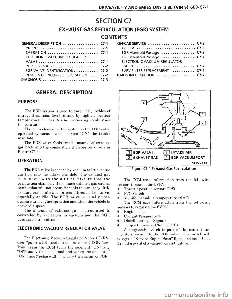
The EGR valve feeds small
amounts of exhaust
gas back into the combustion chamber as shown in
Figure C7-1.
OPERATION
..................... ON-CAR SERVICE C7-3
EGR VALVE
........................ C7-3
EGR Manifold Passage
............... C7-3
EGR Manifold Passage
............... C7-4
ELECTRONIC VACUUM REGULATOR
VALVE
.......................... C7-4
EVRV FILTER REPLACEMENT
.......... C7-4
................. PARTS INFORMATION C7-4
EGR VALVE INTAKE AIR
1 EXHAUST GAS EGR VACUUM PORT I
The EGR valve is opened by vacuum to let exhaust
gas flow into the intake manifold.
l'he exhaust gas
then moves
witb the airlfuel mixture into the
combustion chamber. If too much exhaust gas enters,
combustion will not occur. For this reason, very little
exhaust gas is allowed to pass through the valve,
especially at idle. The
EGR valve is usually open
during warm engine operation and when the vehicle is
above idle speed.
The amount of exhaust gas recirculated is
controlled by variations in vacuum and the EGR
vacuum control solenoid.
ELECTRONIC VACUUM REGULATOR VALVE
The Electronic Vacuum Regulator Valve (EVRV)
uses "pulse width modulation" to control EGK flow.
This
means the ECM turns the solenoid "ON" and
"OFF many times a second and varies the amount of
"ON" time ("pulse width") to vary the amount ot'HGK.
Figure C7-1 Exhaust Gas Recirculation
The i1:CM uses information from the following
sensors to enable the EVRV:
@ Throttle position sensor ('I'PS)
@ Plh' Switch
Manifold
ahsolute temperature (MArI')
The ECM uses information from the following
sensors to regulate the EVRV:
@ Engine 1,oad
Coolant Temperature
@ 1)istributor (rpm Signal)
@ Torque Converter Clutch (TCC)
A diagnostic switch is part of the control and
monitors vacuum to the
EGK. valve. 'I'his switch will
trigger a "Service Engine Soon" light, and set a Code
ai ure. 32 in the event of a vacuum circuit f 'I