Page 767 of 1825
6E3-C4-4 2.8L (VIN S) DRIVEABILITY AND EMISSIONS
430 PPLMlHT - 85 - REFERENCE
424
TANIBLK
453 BLWRED
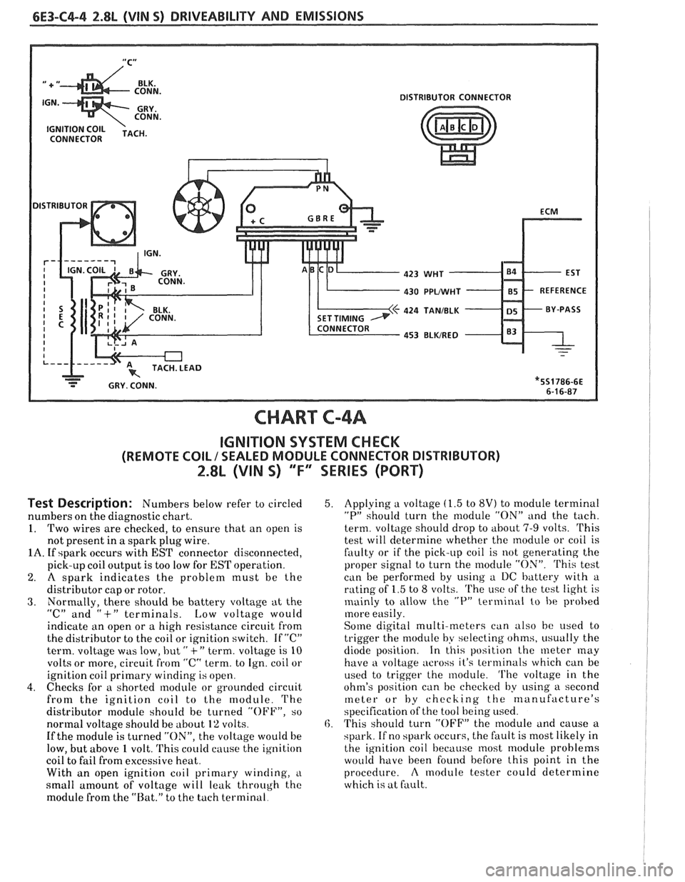
CHART C-4A
IGNITION SYSTEM CHECK
(REMOTE COIL / SEALED MODULE CONNECTOR DISTRIBUTOR)
2.8L (VIN 5) "F" SERIES (PORT)
Test Description: Numbers below refer to circled
numbers on the diagnostic chart.
1. Two wires are checked, to ensure that an open is
not present in
a spark plug wire.
1A. If spark occurs with EST connector disconnected,
pick-up coil output is too low for
EST operation.
2. A spark indicates the problem must be the
distributor cap or rotor.
3. Normally, there should he battery voltage at the
"C" and "+" terminals. Low voltage would
indicktte an open or a high resistance circuit from
the distributor to the coil or ignition switch. If
"C"
term. voltage was low, but " +" term. voltage is 10
volts or more, circuit from "C" term. to Ign. coil or
ignition coil primary winding is open.
4. Checks for a shorted module or grounded circuit
from the ignition coil to the module. The
distributor
nodule should be turned "OFF", so
normal voltage should be about
1% volts.
If the module is turned "ON", the voltage would be
low, but above
1 volt. 'I'his could cause the ig~lition
coil to fail from excessive heat.
With an open ignition coil primary
winding, i~
small amount of voltage will leak through the
module from the "Rat." to the tach terminal.
5. Applying a voltage (1.5 to 8V) to module terminal
"P" should turn the nlodule "ON" and the tach.
term. voltage should drop to about
7-9 volts. This
test will determine whether the module or coil is
faulty or if the pick-up coil is not generating the
proper signal to turn the
rnodule "ON". 'Phis test
can be performed by using a I)C battery with a
rating of
1.5 to 8 volts. The i~sc of the test light is
mainly to allow the
"P" terminal to be probed
more easily.
Some digital multi-meters can also be used t,o
trigger the module by selecting ohms, i~sually the
diode position. In this position the meter
may
have a voltage across it's terminals which can be
used to trigger the module.
'I'he voltage in the
ohm's position can be checked by
using a second
meter or by checking the manufacture's
specification of the tool being used.
6. This should turn "OFF" the nlodule and cause a
spark. If no
spark occurs, the fault is most likely in
the ignition coil because most module problems
would have been found before this point in the
procedure.
A moclule tester could determine
which is at fault.
Page 783 of 1825
6E3-C7-6 2.8L (VIN S) DRIWEABIILBTY AND EMISSIONS
I.P. CONN. "G'
450 BLWWHT
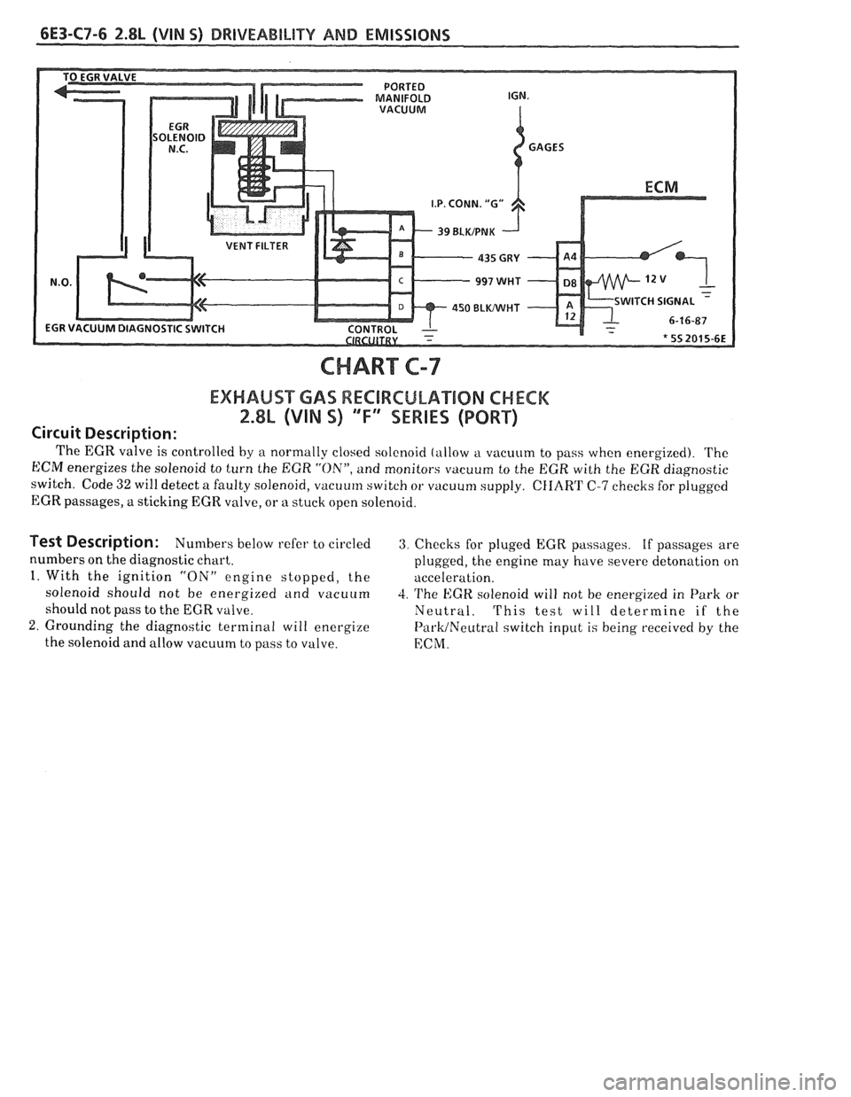
CHART C-7
EXHAUST GAS RECIRCULATION CHECK
2.$h (VIN %) ""F-SERIES (PORT)
Circuit Description:
The EGR valve is controlled by a normally closed solenoid (allow a vacuum to pass when energized). 'I'he
ECM energizes the solenoid to turn the EGR "ON", and monitors vacuum to the EGR with the EGR diagnostic
switch. Code
32 will detect a faulty solenoid, vacuum switch or vacuum supply. CIIART C-7 checks for plugged
EGR passages, a sticking EGR valve, or
n stuck open solenoid.
Test Description: Numbers below refer to circled 3. Checks for pluged EGR passLlges. If passages are
numbers on the diagnostic chart.
plugged, the engine may have severe deton
a t' lon on
1. With the ignition "ON" engine stopped, the
acceleration.
solenoid should not be energized and vacuum
4. The EGR solenoid will not be energized in Park or
should not pass to the EGR valve. Neutral. This test will determine if the
2. Grounding the diagnostic terminal will energize Pal.k/Neutral switch input is being received by the
the solenoid and allow vacuum to pass to valve.
ECM.
Page 784 of 1825
DRIVEABILITY AND EMISSIONS 2.8L (WIN S) 6E3-C7-7
CHART &-7
ASSUMES NO CODE 32 IS STORED
@ DISCONNECT EGR SOLENOID VACUUM HARNESS.
ROTATE HARNESS AND REINSTALL ONLY THE EGR VALVE SIDE.
@ CHECK PORTED VACUUM SOURCE TO SOLENOID ( IF NOT OK, REPAlR ). @ INSTALL A HAND HELD VACUUM PUMP WITH GAGE ON MANIFOLD SIDE
OF EGR SOLENOID.
@a IGNITION "ON", ENGINE STOPPED. @ DIAGNOSTIC TERMINAL NOT GROUNDED. @ APPLY VACUUM. @a OSBSERVE EGR VALVE.
REPLACE EGR
CHECK
CKT435 FOR SHORT TO GROUND. IF MOT SHORTED, IT IS FAULTY ECM. SEE ECM QUAD
@ CHECK PASSAGES FOR BEING PLUGGED.
IF NOT PLUGGED REPLACE EGR VALVE.
REPLACE EGR
VACUUM LINES, PERFORM
PIN SWITCH CHECK. CHART C-1A A,'T
Page 793 of 1825
6E3-C10-2 2.8L (VIN S) DRIVEABILITY AND EMISSIONS
A/C CONTROL
DK GRNNVHT 59
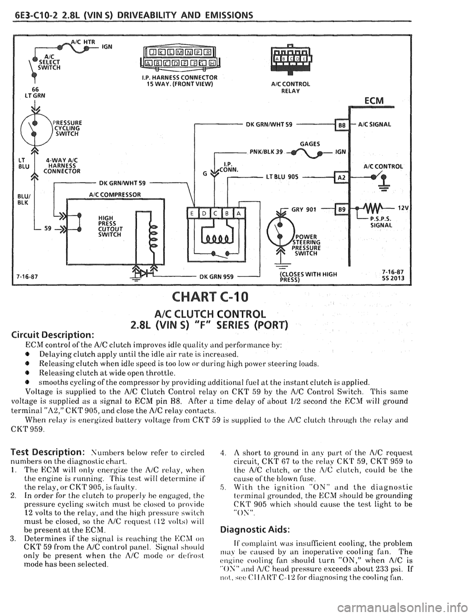
CHART C-10
AIC CLUTCH CONTROL
2.8L (VIN S) "F" WRIES (PORT)
Circuit Description:
ECM control of the A/C clutch improves idle quality and performance by:
Delaying clutch apply
until the idle air rate is increased.
e Releasing clutch when idle speed is too low or during high power steering loilds.
e Releasing clutch a1 wide open throttle.
smooths cyclingof the compressor by providing additional fuel at the instant clutch
is applied.
Voltage is supplied to the
NC Clutch Control relay on CKT 59 by the NC Control Switch. This saine
voltage is supplied as a signal to ECM pit1 88. After a time delay of about 112 second the ECM twill ground
terminal
"A2," CKT 905, and close the A/C relay contacts.
When
relay is energi~etf battery vollage from CKT 59 is supplied to the IVC clulch lhroug11 Ihe txlay arid
CKT 959.
Test Description: Numbers below refer to circled
numbers on the diagnostic chart.
1. The ECM will only energize the A/C relay, when
the engine is running.
'I'his lest will determine if
the relay, or CK'F 905, is Sauity.
2. In order for the clutch to proper1.y be engaged, the
pressure cycling switch must bc closc!cl to provide
12 volts to the relay,
ilnd the high pressure switch
must be closed, so the
AlC rtquest (12 volts) wlll
be present at the ECNI.
3. Determines if the signal is ~.eachitlg the I4:CAI on
CKT 59 from the A/C control panel. Signal hhoitld
only be present when the AlC mode or tlcl'rost
mode has been selected.
4. A short to ground in any part ot' the A/C request
circuit, CKT
67 to the relay CKrI' 59, CKT 959 to
the NC clutch, or the
:2/C clutch, coulcl be the
cause
ofthe blown fiise.
5. With the ignition "ON" and the diagnostic
tcrminal grounded, the ECM should be grounding
CKT 905 which should cause the test light to be
"ON".
Diagnostic Aids:
If complaint was insufficient cooling, the problem
111~1,~ be ciiuscd by an inoperalive cooling fan. 'I'he
t!11gine cooling fan should turn "ON," when AlC is
"ON" ,tntl cZ/C head pressure exceeds about 233 psi. If
not. qctt: ("I Iclli'I' C-12 for diagnosing the cooling fan.
Page 799 of 1825
6E3-C12-4 2.8L (VIN S) DRIVEABILITY AND EMISSIONS
I.P. HARNESS CONNECTOR
(FRONT VIEW)
TO ALTERNATOR
DK GRNNVHT 335
FAN CONTROL SWITCH
CHART C-12
(Page 2 of 2)
COOLING FAN CONTROL CIRCUIT
2.8L (VIN S) "F" SERIES (PORT)
Test Description: Numbers below refer to circled
The SES light should also be flashing, at this
numbers on the diagnostic chart.
point. If it isn't flashing, see
CHART A-2.
1. 12 volts should be available to both terminal "E" 3. If the fan docs not turn "ON", at this point, CKT
& "C", when the ignition is "ON". 936 or CKT 150 is open, or the cooling fan motor is
2. This test checks the ability of the ECM to ground
faulty.
CK'I' 335.
Page 813 of 1825
TO MAF SENSOR
POWER & BURN-OFF
RELAY, OIL PRESS. SW.
.....-
439 PNKIBLK
419 BRNNVHT
SERIAL DATA
451 WHTIBLK
450
BLWHT
ALDL CONNECTOR
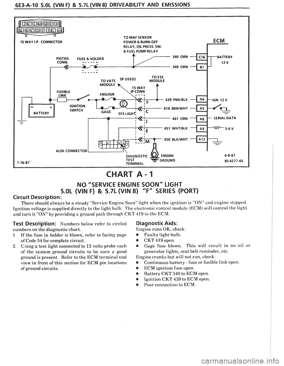
CHART A - 1
NO "'SERVICE ENGINE SOON" LIGHT
5.OL (VIN F) & 5.7L (VIN 8) "F'XSEBIE'S (PORT)
Circuit Description:
There should always be a steady "Service Engine Soon" light when the ignition is "ON" and engine stoppccl.
Ignition voltage is supplied directly to the light bulb. The electronic control module (ECM) will control the light
and turn it
"ON" by providing a ground path through CKT 419 to the ECM.
Test Description: Numbers below refer to circled
numbers on the diagnostic chart.
1. If the fuse in holder is blown, refer to facing page
of Code
54 for complete circuit.
2. Using a test light connected to 12 volts probe each
of the system ground circuits to be sure a good
ground is present. Refer to the ECM terminal end
view in front of this section for ECM pin locations
of ground circuits.
Diagnostic Aids:
Engine runs OK, check:
r Faulty light bulb.
@ CKrI' 419 open.
@ Gage fuse blown. This
will result in no oil or
generator lights, seat belt reminder, etc.
Engine cranks but will not run, check:
r Continuous battery - fuse or fusible link open.
@ ECM ignition fuse open.
r Battery CKT 340 to ECM open.
@ Ignition CKT 439 to ECM open.
@ Poor connection to ECM.
Page 814 of 1825
DRIVEABILITY AND EMISSIONS 5.0L (VIN F) & 5.7L (WIN 8) 6E3-A-11
@ DISCONNECT ECM CONNECTORS.
e IGNITION "ON"
PROBE
CKT419, WITH TEST LIGHT
TO GROUND.
- GAGE FUSE
- FAULTY BULB PROBE
CKT 340 & 439 CKT
THAT HAD A
- OPEN CKT 419 WITH TEST LIGHT TO
- CKT 419 SHORTED TO
IS THE LIGHT "ON" ON
- OPEN IGN. FEED TO
HAT DID NOT LIGHT
Page 815 of 1825
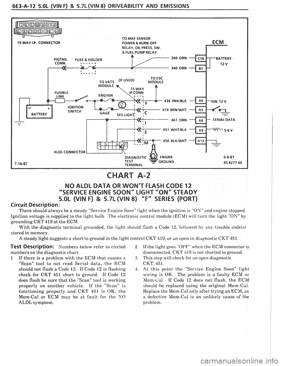
6E3-A-12 5.OL (VIN F) & 5.7L (VIN 8) DRIVEABILITY AND EMISSIONS
TO MAF SENSOR
POWER & BURN-OFF
, . . . . .
439 PNWBLK
419 BRNNVHT
SERIAL DATA
451
WHTIBLK
450 BLKIWHT
ALDL CONNECTOR
CHART A-2
NO ALDL DATA OR WON'T FLASH CODE 12
""SERVICE ENGINE SOON" LIGHT '"ON" STEADY
5.OL (VIN F) & 5.7L (VIN 8) ""FYEERIES (PORT)
Circuit Description:
'I'here should always be a steady "Service Engine Soon" light when the ignition is "ON" and engine stopped.
Ignition voltage is supplied to the light bulb.
'I'he electronic control module (ECM) will turn the light "ON" by
grounding CKT 419 at the ECM.
With the diagnostic terminal grounded, the light should flash
a Code 12, followed by any trouble code(s)
stored in memory.
A steady light suggests a short to ground in the light control CKT 419, or tin open in cliagnostic CKT 451.
Test Description: Numbers below refer to circled
numbers on the diagnostic chart.
1. If there is a problem with the ECM that causes
a
"Scan" tool to not read Serial data, the ECM
should not flash a Code 12. If Code 12 is flashing
check for CKT 451 short to ground. If Code 12
does flash be sure that the "Scan" tool is working
properly on another vehicle. If the "Scan" is
functioning properly and CKT 461 is OK, the
Mem-Cal or ECM may be at fault for the NO
ALDL symptom. 2.
If
the light goes
"OFF" when the ECM connector is
disconnected,
CK'r 419 is not shorted to ground.
3. This step will check for an open diagnostic
CKT 451.
-2. At this point the "Service Engine Soon" light
wiring is OK. The problem is a faulty ECM or
Mem-Cal. If Code 12 does not flash, the ECM
should be replaced using the original Mem-Cal.
Replace the Mem-Cal only after trying an ECM, as
a defective Mem-Cal is an unlikely cause of the
problem.