1988 PONTIAC FIERO ignition
[x] Cancel search: ignitionPage 843 of 1825
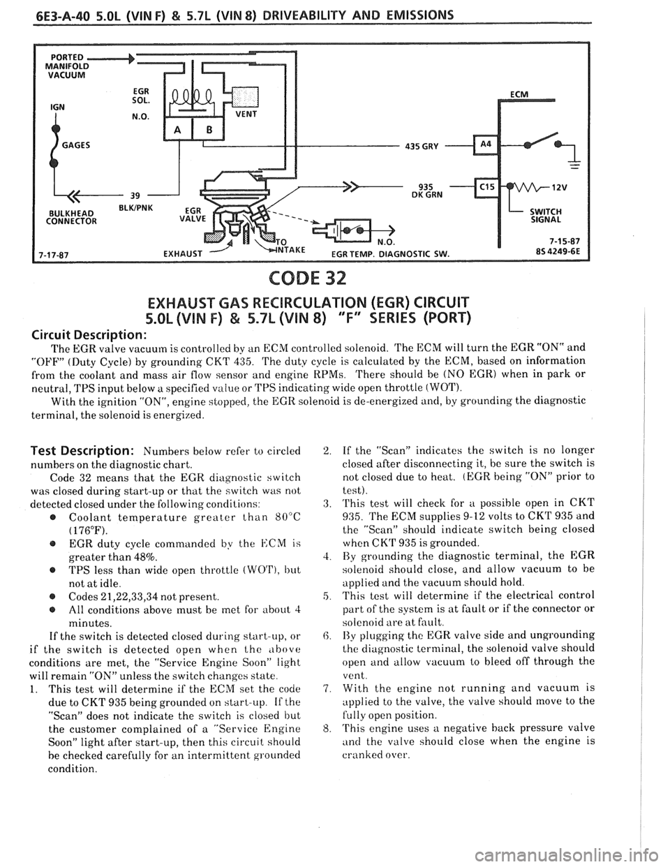
CODE 32
EXHAUST GAS RECBRCULATION (EGR) CIRCUIT
%.OL (VIN F) & 5.7L (VIN 8) "F" SERIES (PORT)
Circuit Description:
The EGR valve vacuum is controlled by an ECM controlled solenoid. 'I'he ECM will turn the EGR "ON" and
"OFF" (Duty Cycle) by grounding CKT 435. 'I'he duty cycle is calculated by the ECM, based on information
from the coolant and mass air flow sensor and engine
RPMs. 'I'here should be (NO EGR) when in park or
neutral,
TPS input below a specified value or TPS indicating wide open throttle (WOT).
With the ignition "ON", engine stopped, the EGR solenoid is de-energized and, by grounding the diagnostic
terminal, the solenoid is energized.
Test Description: Numbers below refer to circled
numbers on the diagnostic chart.
Code 32 means that the
EGR diagnostic switch
was closed during start-up or that the switch was not
detected closed under the following conclilions:
@ Coolant temperature greater than 80°C
( 176°F).
@ EGR duty cycle commanded by the ISCM is
greater than
48%.
@ TPS less than wide open throttle (WO'I'), but
not at idle.
@ Codes 21,22,33,34 not present.
@ All conditions above must be met for about 4
minutes.
If the switch is detected closed during start-up, or
if the switch is detected open when the
,lbove
conditions are met, the "Service Engine Soon" light
will remain
"ON" unless the switch changes state.
1. This test will determine if the ECM set the code
due to CKT 935 being grounded on start-up.
If the
"Scan" does not indicate the switch is closed but
the customer complained of a "Service Engine
Soon" light after start-up, then this circuit should
be checked carefully for an intermittent grounded
condition.
2. If the "Scan" indicates the switch is no longer
closed after disconnecting it, be sure the switch is
not closed due to heat.
(EGR being "ON" prior to
test).
3. 'I'his test will check for
u possible open in CKT
935. 'I'he EXM supplies 9-12 volts to CKrl' 935 and
the "Scan" should indicate switch being closed
when CK'P 935 is grounded.
4. By grounding the diagnostic terminal, the EGR
solenoid should close, and allow vacuum to be
applied and the vacuum should hold.
5. This test will determine if the electrical control
part of the system is at fault or if the connector or
solenoid are at fault.
6. I3y plugging the EGR valve side and ungrounding
the diagnostic terminal, the solenoid valve should
open and allow vacuum to bleed off through the
vent.
7. With the engine not running and vacuum is
applied to the valve, the valve should
move to the
fully open position.
8. 'I'his engine uses a negative back pressure valve
and the valve should close when the engine is
cranked over.
Page 845 of 1825
6E3-A-42 S.OL (VIN F) & 5.7L (VIN 8) DRIVEABILITY AND EMISSIONS
SYSTEM GND
SYSTEM GND
SYSTEM GND
ANALOG GND
BURN-OFF CONTROL CKT
-
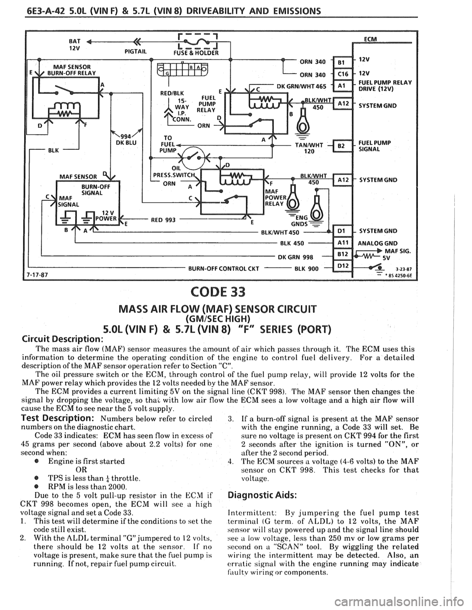
CODE 33
MASS AIR FLOW (MAF) SENSOR CIRCUIT
(GMISEC HIGH)
5.OL (VIN F) & 5.7L (VIN 8) ""FY"IES (PORT)
Circuit Description:
The mass air flow (MAF) sensor measures the amount of air which passes through it. The ECM uses this
information to determine the operating condition of the engine to control fuel delivery.
For
a detailed
description of the MAF sensor operation refer to Section
"C".
The oil pressure switch or the ECM, through control of the fuel pump relay, will provide 12 volts for the
MAF power relay which provides the
12 volts needed by the MAF sensor.
The ECM provides
a current limiting 5V on the signal line (CKT 998). The MAF sensor then changes the
signal by dropping the voltage, so thai with low air flow the ECM sees
a low voltage and a high air flow will
cause the ECM to see near the
5 volt supply.
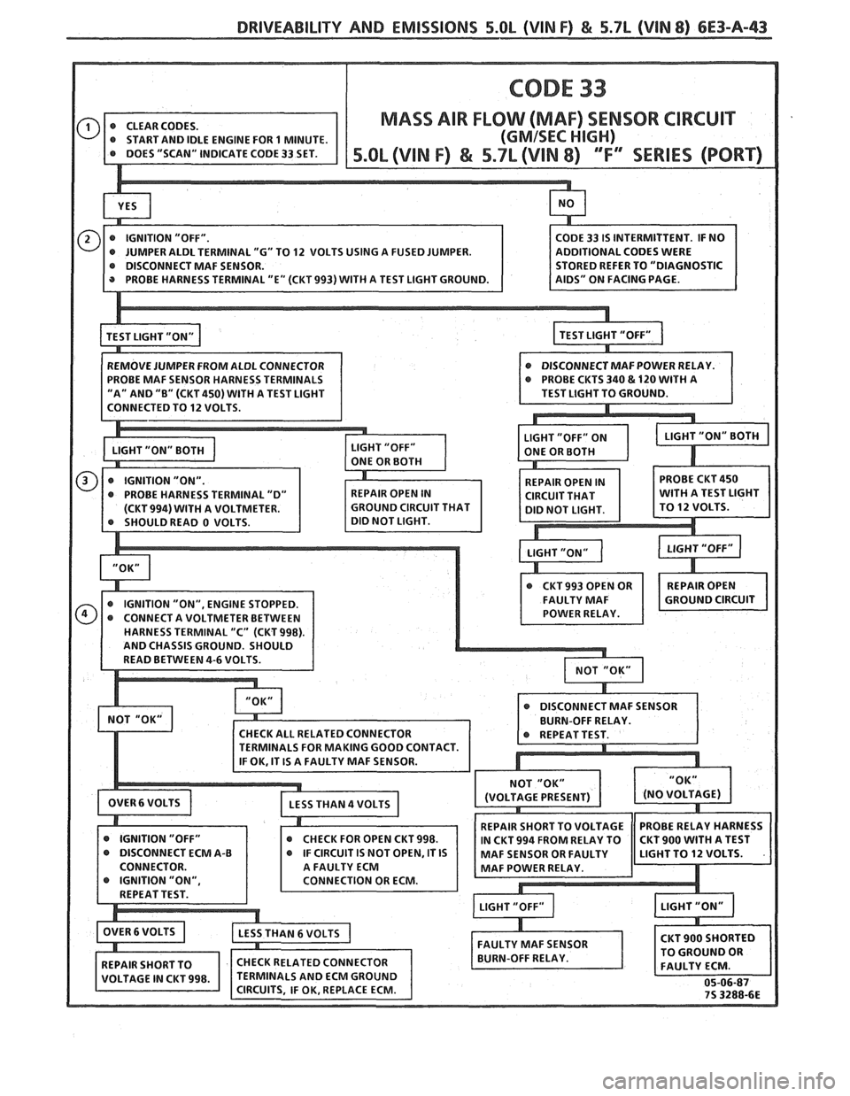
Test Description: Numbers below refer to circled 3. If a burn-off signal is present at the MAF sensor
numbers on the diagnostic chart.
with the engine running, a Code
33 will set. Be
Code
33 indicates: ECM has seen flow in excess of
sure no voltage is present on CKT 994 for the first
45 grams per second (above about 2.2 volts) for one 2 seconds after the ignition is turned "ON", or
second when: after the
2 second period.
@ Engine is first started 4. The ECM sources a voltage (4-6 volts) to the MAF
OR sensor on CKT 998. This test checks for that
@ TPS is less than 4 throttle. voltage. @ RPM is less than 2000.
Due to the 5 volt pull-up resistor in the ECM if Diagnostic Aids:
CKT 998 becomes open, the ECM will see a high
voltage signal and set
a Code 33. Intermittent:
By jumpering the fuel pump test
1. This test will determine if the conditions to set the terminal (G term, of ALDL) to 12 volts, the MAF
code still exist. sensor will stay powered up and the signal line should
2. With the ALDL terminal "G" jumpered to 12 volts,
see a low voltage, less than 250 mv or low grams per
there should be
12 volts at the sensor. If no second on a "SCAN" tool. By wiggling the related
voltage is present, make sure that the fuel pump
is wiring the intermittent may be detected. Also, an
running.
If not, repair fuel pump circuit. erratic signal with the engine running may indicate
fili~ltv wirinq or components.
Page 846 of 1825
DRIVEABILITY AND EMISSIONS 5.OL (VIN F) & 5.7L (VIM 8) 6E3-A-43
ADDITIONAL CODES WERE
@ IGNITION "OFF" @ CHECK FOR OPEN CKT 998.
Page 849 of 1825
6E3-A-46 5.Ob (VIN F) & 5.7b (VIN 8) DRIVEABILITY AND EMISSIONS
SYSTEM GND
SYSTEM GND
SYSTEM GND
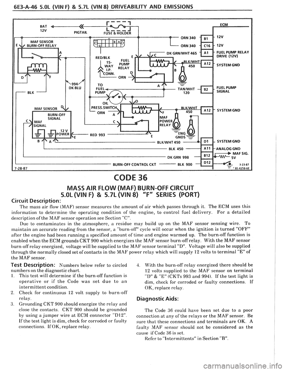
CODE 36
MASS AIR FLOW (MAF) BURN-OFF CIRCUIT
5.Qh (VlN F) & 5.7L (VIN 8) ""F9SERlES (PORT)
Circuit Description:
The mass air flow (MAF) sensor measures the amount of air which passes through it. The ECM uses this
information to determine the operating condition of the engine, to control fuel delivery. For
a detailed
description of the MAF sensor operation see Section
"C".
Due to contaminates in the atmosphere, a residue may build up on the MAF sensor sensing wire. To
maintain an accurate reading from the sensor, a "burn-off' cycle will occur when the ignition is turned "OFF"
after the engine had been running a specified amount of time and engine warmed up. The burn-off function is
enabled when the ECM grounds
CKT 900 which energizes the MAF sensor burn-off relay. With the MAF sensor
burn-off relay energized, voltage will be supplied to the MAF sensor terminal
"D". Voltage will also be supplied
through the normally closed set of contacts in the MAF power relay which will supply 12 volts to terminal
"E" of
the MAF sensor.
Test Description: Numbers below refer to circled
numbers on the diagnostic chart.
1. This test will determine if the burn-off function is
operative or if the Code was set due to an
intermittent condition.
2. Check for continuous 12 volt supply to burn-off
relay.
3. Grounding CKT 900 should energize the relay and
close the contacts. CKT 900 should be grounded
by using a jumper wire at ECM connector
"D12".
If the test light is dim, check for corroded or faulty
connections. If OK, replace relay.
3. With the burn-off relay energized there should be
12 volts supplied to the MAF sensor on terminal
"1)" & "E:" (CK'I's 993 and 994). If the test light is
dim, check for corroded or faulty connections. If
OK, replace relay.
Diagnostic Aids:
The Code 36 could have been set due to a poor
connection at
any of the relays or the MAF sensor. Be
sure that these connections and terminals are OK.
A
faulty MAF sensor should not be considered as the
cause
if Code 36 is set.
Refer
to "intermittents" in Section "R".
Page 853 of 1825
6E3-A-50 5.OL (VIN F) & 5.7L (VIN 8) DRI\/EABILITY AND EMISSIONS
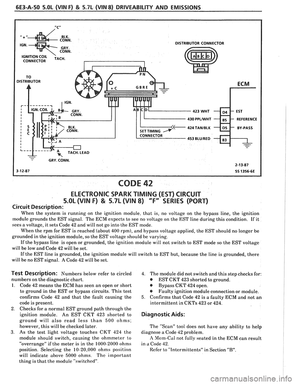
430 PPUWHT
424 TANIBLK
CODE 42
ELECTRONIC SPARK "TIMING (EST) CIRCUIT
5.011, (VIN F) & 5.7L (VIN 8) ""FYESERIES (PORT)
Circuit Description:
When the system is running on the ignition module, that is, no voltage on the bypass line, the ignition
[nodule grounds the EST signal. The ECM expects to see no voltage on the EST line during this condition. If it
sees a voltage, it sets Code
42 and will not go into the EST mode.
When the rpm for EST is reached (about
400 rpm), and bypass voltage applied, the EST should no longer be
grounded in the ignition module, so the EST voltage should be varying.
If the bypass line is open or grounded, the ignition module will not switch to EST mode so the EST voltage
will be low and Code
42 will be set.
If the EST line is grounded, the ignition module will switch to EST but, because the line is grounded, there
will be no EST signal.
A Code 42 will be set.
Test Description: Numbers below refer to circled
numbers on the diagnostic chart.
1. Code 42 means the ECM has seen an open or short
to ground in the EST or bypass circuits. This test
confirms Code
42 and that the fault causing the
code is present.
2. Checks for a normal EST ground path through the
ignition module. An EST CKT
423 shorted to
ground will also read less than
500 ohms;
however, this will be checked later.
3. As the test light voltage touches CKT 324 the
module should switch, causing the ohmmeter
to
"overrange" if the meter is in the 1000-2000 ohms
position. Selecting the
10-20,000 ohms position
will indicate above
5000 ohms. The important
thing is that the module "switched"
4. The module did not switch and this step checks for:
@ EST CKT 423 shorted to ground.
@ Bypass CKT 424 open.
@ Faulty ignition module connection or module.
5. Confirms that Code 42 is a faulty ECM and not an
intermittent in
CKTs 423 or 424.
Diagnostic Aids:
The "Scan" tool does not have any ability to help
diagnose a Code
42 problem.
A Mem-Cal not fully seated in the ECM can result
in
a Code 42.
Kefer to "Intermittents" in Section "R".
Page 855 of 1825
6E3-A-52 5.OL (VIN F) & 5.7L (VIN 8) DRIVEABILITY AND EMISSIONS
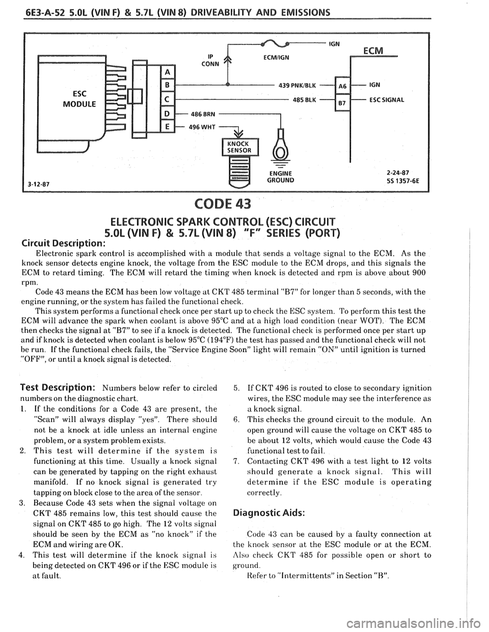
CODE 43
ELECTRONIC SPARK CONTROL (ESC) ClRCUlT
5.OL (VIN F) & 5.7L (VIN 8) 'TF" SERIES (PORT)
Circuit Description:
Electronic spark control is accomplished with a module that sends a voltage signal to the ECM. As the
knock sensor detects engine knock, the voltage from the ESC module to the ECM drops, and this signals the
ECM to retard timing. The ECM will retard the timing when knock is detected and rpm is above about 900
rpm.
Code 43 means the ECM has been low voltage at CKT 485 terminal
"R7" for longer than 5 seconds, with the
engine running, or the system has failed the functional check.
This system performs a functional check once per start up to check the
ESC system. To perform this test the
ECM will advance the spark when coolant is above 95°C and at a high load condition (near
WOT). The ECM
then checks the signal at
"B7" to see if a knock is detected. The functional check is performed once per start up
and if knock is detected when coolant is below 95°C
(194°F') the test has passed and the functional check will not
be run. If the functional check fails, the "Service Engine Soon" light will remain
"ON" until ignition is turned
"OFF", or until a knock signal is detected.
Test Description: Numbers below refer to circled
numbers on the diagnostic chart.
1. If the conditions for a Code 43 are present, the
"Scan" will always display "yes". There should
not be a knock at idle unless an internal engine
problem, or
a system problem exists.
2. This test will determine if the system is
functioning at this time. Usually
a knock signal
can be generated by tapping on the right exhaust
manifold. If no knock signal is generated try
tapping on block close to the area of the sensor.
3. Because Code 43 sets when the signal voltage on
CKT 485 remains low, this test should cause the
signal on CKT 485 to go high. The
12 volts signal
should be seen by the ECM as "no knock" if the
ECM and wiring are OK.
4. This test will determine if the knock signal
is
being detected on CKT 496 or if the ESC module is
at fault. 5.
If CKT
496 is routed to close to secondary ignition
wires, the ESC module may see the interference as
a knock signal.
6. This checks the ground circuit to the module. An
open ground will cause the voltage on CKT 485 to
be about
12 volts, which would cause the Code 43
functional test to fail.
7. Contacting CKT 496 with a test light to 12 volts
should generate a knock signal. This will
determine if the ESC module is operating
correctly.
Diagnostic Aids:
Code 33 can be caused by a faulty connection at
the knock sensor at the ESC module or at the ECM.
Also check CKT 485 for possible open or short to
ground.
Refer to "Intermittents" in Section "R".
Page 859 of 1825
6E3-A-56 5.OL (VIN F) & 5.7L (VIN 8) DRIVEABILITY AND EMISSIONS
OXYGEN ( O2 )SENSOR
-
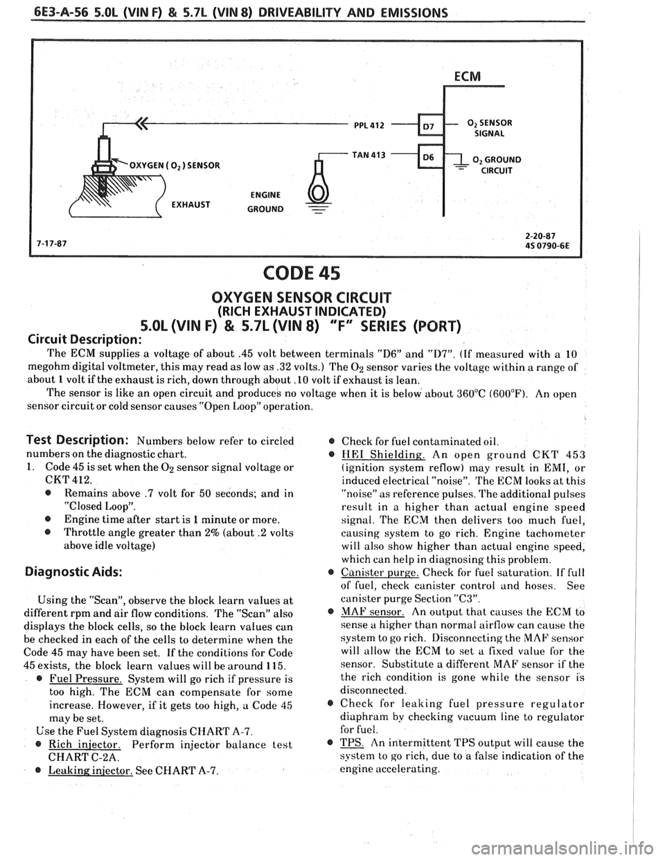
CODE 45
OXYGEN SENSOR CIRCUIT
(RICH EXHAUST INDICATED)
S.OL (VIN F) & 5.7L (VIN 8) ""F-ERIES (PORT)
Circuit Description:
The ECM supplies a voltage of about .45 volt between terminals "D6" and "D7". (If measured with a 10
megohm digital voltmeter, this may read as low as .32 volts.) The
02 sensor varies the voltage within a range of
about 1 volt if the exhaust is rich, down through about .10 volt if exhaust is lean.
The sensor is like an open circuit and produces no voltage when it is below about 360°C (600°F). An open
sensor circuit or cold sensor causes "Open Loop" operation.
Test Description: Numbers below refer to circled @ Check for fuel contaminated oil.
numbers on the diagnostic chart.
@ HE1 Shielding. An open ground CKT 453
1. Code 45 is set when the
02 sensor signal voltage or
(ignition system reflow) may result in EMI, or
CKT 412.
induced electrical "noise". The ECM looks at this
@ Remains above .7 volt for 50 seconds; and in
"noise" as reference pulses. The additional pulses
"Closed Loop".
result in a higher than actual engine speed
@ Engine time after start is 1 minute or more.
signal. The ECM then delivers too much fuel,
@ Throttle angle greater than 2% (about .2 volts
causing system to go rich. Engine tachometer
above idle voltage) will also show higher than actual engine speed,
which can help in diagnosing this problem.
Diagnostic Aids: @ Canister purge. Check for fuel saturation. If full
of fuel, check canister control and hoses. See
Using the "Scan", observe the block learn values at canister
purge Section
"C3".
different rpm and air flow conditions. The "Scan" also @ MAF sensor. An output that causes the ECM to
displays the block cells, so the block learn values can sense
a higher than normal airflow can cause the
be checked in each of the cells to determine when the system
to go rich. Disconnecting the MAF sensor
Code 45 may have been set. If the conditions for Code will
allow the ECM to set a fixed value for the
45 exists, the block learn values will be around 115. sensor.
Substitute a different MAF sensor if the
@ Fuel Pressure. System will go rich if pressure is the
rich condition is gone while the sensor is
too high. The ECM can compensate for some disconnected.
increase. However, if it gets too high, a Code 45
@ Check for leaking fuel pressure regulator
may be set. diaphram
by checking vacuum line to regulator
Use the Fuel System diagnosis CHART A-7. for
fuel.
@ Rich
iniector. Perform injector balance test @ TPS. An intermittent TPS output will cause the
CHART C-2A.
system to go rich, due to a false indication of the
@ Leaking injector. See CHART A-7. engine
accelerating.
Page 861 of 1825
6E3-A-58 5.OL (VIN F) & 5.7L (VIN 8) DRIVEABILITY AND EMISSIONS
PNKIBLK 439
PPL 963
5V
IP CONN.
DECODER
MODULE
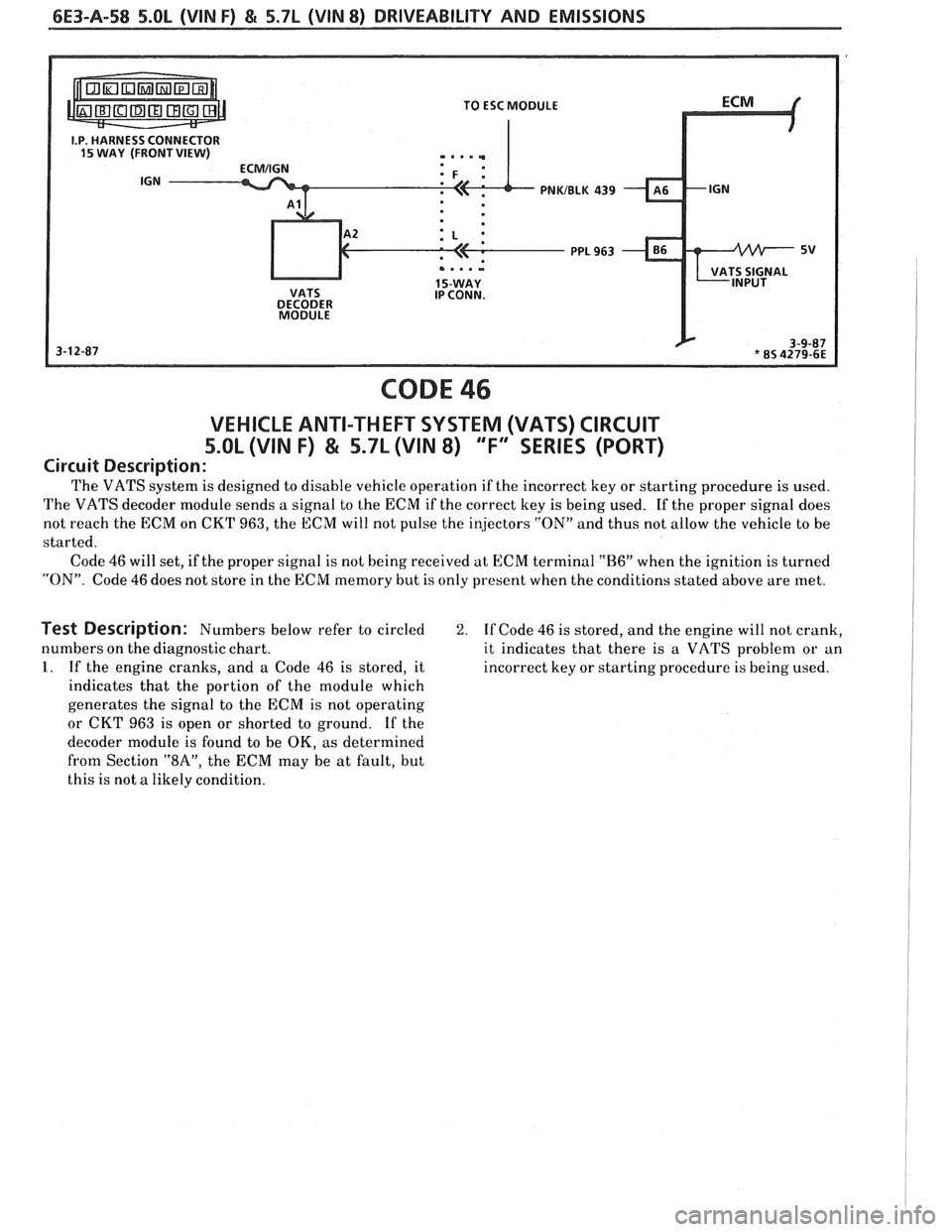
CODE 46
VEHICLE ANTI-THEFT SYSTEM (VATS) CIRCUIT
5.OL (VIN F) & 5.7L (VIN 8) 'TF'3SERlES (PORT)
Circuit Description:
The VATS system is designed to disable vehicle operation if the incorrect key or starting procedure is used.
The VATS decoder module sends a signal to the ECM if the correct key is being used. If the proper signal does
not reach the ECM on CKT 963, the ECM will not pulse the injectors
"ON" and thus not allow the vehicle to be
started.
Code
46 will set, if the proper signal is not being received at ECM terminal "B6" when the ignition is turned
"ON". Code 46 does not store in the ECM memory but is only present when the conditions stated above are met.
Test Description: Numbers below refer to circled 2. If Code 46 is stored, and the engine will not crank,
numbers on the diagnostic chart. it indicates that there is a VATS problem or an
1. If the engine cranks, and a Code 46 is stored, it incorrect key or starting procedure is being used.
indicates that the portion of the module which
generates the signal to the ECM is not operating
or CKT 963 is open or shorted to ground. If the
decoder module is found to be
OK, as determined
from Section
"8AV, the ECM may be at fault, but
this is not a likely condition.