1988 PONTIAC FIERO center console
[x] Cancel search: center consolePage 1499 of 1825
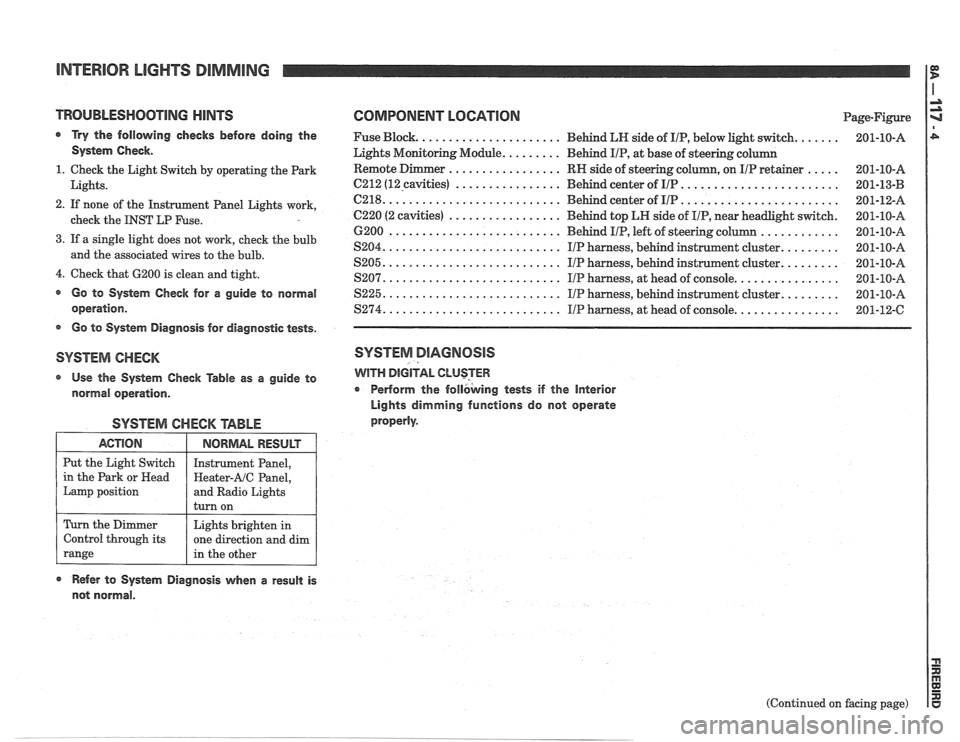
INTERIOR LIGHTS DIMMING
TROUBLESHOOTlNG HINTS COMPONENT LOGATlON Page-Figure
a Try the following checks before doing the Fuse Block. ..................... Behind LN side of IIP, below light switch. ...... 201-10-A
System Check. Lights Monitoring Module. ........ Behind IIP, at base of steering column
................. ..... 1. Check the Light Switch by operating the Park RN
side of steering column, on IIP retainer 201-10-A
................ ........................ Lights. 6212 (12-cavities) Behind center of IIP 201-13-B -
.......................... ........................ 2. If none of the Instrument Panel Lights work, C218. Behind center of IIP 201-12-A
................. check the INST LP Fuse. C220 (2 cavities) Behind top LH side of IIP, near headlight switch. 201-10-A
............ 6200 .......................... Behind IIP, left of steering column 201-10-A
3. If a single light does not work, cheek the bulb ........ S204. .......................... IIP harness, behind instrument cluster. 201-10-A and the associated wires to the bulb. ........ S205. .......................... IIP harness, behind instrument cluster. 201-10-A
4. Check that 6200 is clean and tight. ............... S207. .......................... IIP harness, at head of console. 201-10-A
@ Go to System Check for a guide to normal S225. .......................... IIP harness, behind instrument cluster. ........ 201-10-A
operation. $274. .......................... IIP harness, at head of console. ............... 201-12-C
s Go to System Diagnosis for diagnostic tests.
SYSTEM CHECK SYSTEM DIAGNOSIS
Use the System Check Table as a guide to WITH DIGITAL CLUSTER
normal operation. r Perform
the follbking tests if the Interior
Lights dimming functions do not operate
properly.
SYSTEM CHECK TABLE
ACTION
Put the Light Switch
in the Park or
Head
Lamp position
Refer to System Diagnosis when a result is
not normal.
NORMAL RESULT
Instrument Panel,
Heater-AIC Panel,
and Radio Lights
turn on
Turn the Dimmer
Control through its
range
(Continued on facing page)
Lights brighten
in
one direction and dim
in the other
Page 1504 of 1825
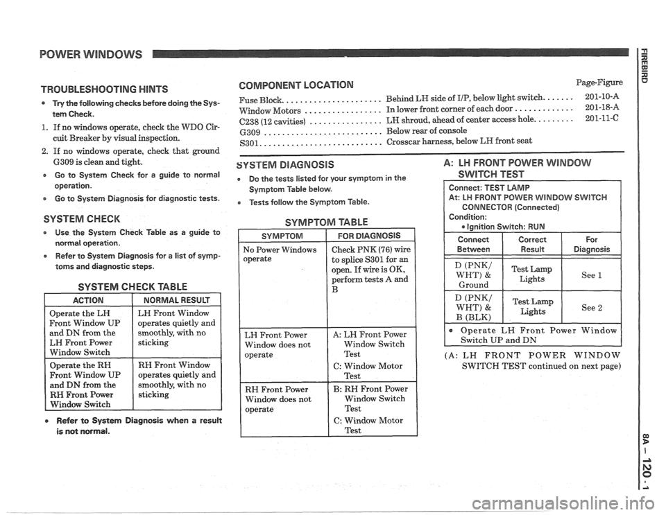
POWER WINDOWS
TROUBLESHOOTING HINTS
s Try the following checks before doing the Sys-
tem Check.
1. If no windows operate, check the WDO Cir-
cuit Breaker by visual inspection.
2. If no windows operate, check that ground
6309 is clean and tight.
e Go to System Check for a guide to normal
operation.
e Go to System Diagnosis for diagnostic tests.
COMPONENT LOCNIOM Page-Figure
..................... ...... Fuse Block. Behind LH side
of IIP, below light switch. 201-10-A
................. ............. VVindow Motors In lower front corner of each door 201-18-A
................ ........ C238 (12 cavities) LH shroud, ahead of center access hole. 201-11-C
.......................... 6309 Below rear of console
.......................... S301. Crosscar harness, below LR front seat
SYSTEM DIAGNOSIS A: LH FRONT POWER WINDOW
e Do the tests listed for your symptom in the SWITCH TEST
Symptom Table below.
e Tests follow the Symptom Table.
SYSTEM CHECK SYMPTOM TABLE
* Use the System Check Table as a guide to
normal operation.
Refer to System Diagnosis for a list of symp-
toms and diagnostic steps.
SYSTEM CHECK TABLE
and DN from the
moothly, with no
EH Front Power
Window Switch
RH Front Window
RH Front Power
r Refer to System Diagnosis when a result
is not normal.
to splice S301 for an
open. If wire is OK,
perform tests A and
RH Front Power
Window does not Window Switch
CONNECTOR (Connected)
(A: LN FRONT POWER WINDOW
SWITCH TEST continued on next page)
Page 1512 of 1825
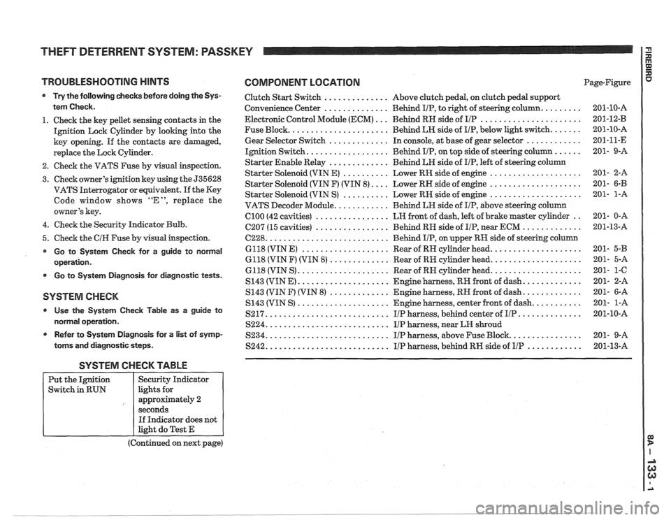
THEFT DETERRENT SYSTEM: PASSKEY I a
TROUBLESHOOTING HINTS COMPONENT LOCATION
Try the following checks before doing the Sys-
tem Check.
1. Check the key pellet sensing contacts in the
Ignition Lock Cylinder by looking into the
key opening. If the contacts are damaged,
replace the Lock Cylinder.
2. Check the VATS Fuse by visual inspection.
3. Check owner's ignition key using the 535628
VATS Interrogator or equivalent.
If the Key
Code window shows "E", replace the
owner's key.
4. Check the Security Indicator Bulb.
5. Check the
CIH Fuse by visual inspection.
Go to System Check for a guide to normal
operation.
Go to System Diagnosis for diagnostic tests.
SYSTEM CHECK
Use the System Check Table as a guide to
normal operation.
r Refer to System Diagnosis for a list of symp-
toms and diagnostic steps.
Clutch Start Switch .............. Above clutch pedal, on clutch pedal support
Convenience Center
.............. Behind IIP, to right of steering column. ........
Electronic Control Module (ECM) ... Behind RN side of IIP ......................
Fuse Block. ..................... Behind LH side of IIP, below light switch. ......
Gear Selector Switch ............. In console, at base of gear selector ............
Ignition Switch. ................. Behind IIP, on top side of steering column ......
Starter Enable Relay ............. Behind LH side of IIP, left of steering column
Starter Solenoid (VIN E)
.......... Lower RH side of engine ....................
Starter Solenoid (VIN F) (VIN 8). ... Lower RH side of engine ....................
Starter Solenoid (VIN S) .......... Lower RN side of engine ....................
VATS Decoder Module. ........... Behind LH side of IIP, above steering column
Cl00 (42 cavities) ................ LH front of dash, left of brake master cylinder ..
C207 (15 cavities) ................ Behind RN side of IIP, near ECM .............
6228. .......................... Behind IIP, on upper RH side of steering column
6118 (VIN
E) ................... Rear of RN cylinder head. ...................
6118 (VIN F) (VIN 8) ............. Rear of RH cylinder head. ...................
6118 (VIN S) .................... Rear of RN cylinder head. ...................
S143 (VIN E) .................... Engine harness, RR front of dash. ............
S143 (VIN F) (VIN 8) ............. Engine harness, RN front of dash. ............
S143 (VIN S) .................... Engine harness, center front of dash. ..........
S217. .......................... IIP harness, behind center of IIP. .............
S224. .......................... IIP harness, near LH shroud
S234. .......................... I/P harness, above Fuse Block. ...............
S242. .......................... IIP harness, behind RH side of IIP ............
SYSTEM CHECK TABLE
(Continued on next page)
Put
the Ignition
Switch in RUN
R aJ XI
Page-Figure u
Security Indicator
lights for
approximately 2
seconds If Indicator does not
light do Test E
Page 1520 of 1825
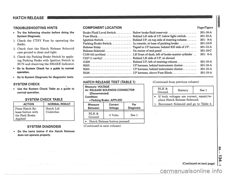
HATCH RELEASE P
E
TROUBLESHOOTING H lNTS
0 Try the following checks before doing the
System Diagnosis.
1. Check the CTSY Fuse by operating the
Radio.
2. Check that the Hatch Release Solenoid
case ground is clean and tight.
3. Check the Parking Brake Switch by apply-
ing Parking Brake with Ignition Switch in
RUN and observing the BRAKE Indicator.
@ Go to System Check for a guide to normal
operation.
Go to System Diagnosis for diagnostic tests.
SYSTEM CHECK -
o Use the System Check fable as a guide to
normal operation.
SYSTEM CHECK TABLE
lease button with
SYSTEM DIAGNOSIS
e Do the tests below if the Hatch Release
does not operate properly.
COMPONENT LOCATION Page-Figure
Brake Fluid Level Switch. ......... Below brake fluid reservoir ..................
Fuse Block. ..................... Behind LN side of IIP, below light switch. ......
Ignition Switch. ................. Behind IIP, on top side of steering column ......
Parking Brake Switch. ............ In console, at base of parking brake ...........
Release Relay ................... Taped to IIP harness, behind RN side of IIP. ....
Release Solenoid ................. On center of end panel ......................
el00 (42 cavities) ................ LN front of dash, left of brake master cylinder ..
C227 (1 cavity) .................. Behind LN side of IIP, at shroud
6200
.......................... Behind IIP, left of steering c
S203. .......................... IIP harness, behind instrunnent cluster. ........
.......................... ........ S205. IIP harness, behind instrument cluster.
S228. .......................... IIP harness, above Fuse Block. ...............
WATGH RELEASE TEST (TABLE 1)
At: RELEASE SOLENOID CONNECTOR
(Disconnected)
I 0 Parkina Brake: APPLIED I
I Measure I Correct I For
(Continued from previous column)
BLK & 1 o volts I See I 1 Ground
I r Hatch Release button pressed I --
(Continued in next column)
(Continued on next page)
Page 1526 of 1825
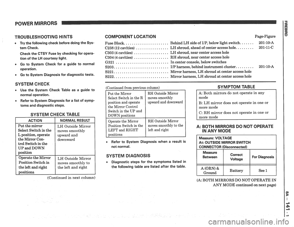
POWER MIRRORS
TROUBLESHOOTING HINTS
e Try the following check before doing the Sys-
tem Check.
Check the CTSY Fuse by checking for opera-
tion of the
LH courtesy light.
a Go to System Check for a guide to normal
operation.
e Go to System Diagnosis for diagnostic tests.
SYSTEM CHECK
0 Use the System Check Table as a guide to
normal operation.
e Refer to System Diagnosis for a list of symp-
toms and diagnostic steps.
SYSTEM CHECK TABLE
the left and right
(Continued in next column)
COMPONENT LOCATION Page-Figure
..................... Fuse Block. Behind
LN side of IIP, below light switch. ...... 201-10-A
C238 (12
cavities) ................ LH shroud, ahead of center access hole. ........ 201-11-C
................. C303 (4 cavities) LN
shroud, near center access hole
C304 (4 cavities) ................. RH shroud, near center access hole
.......................... 6321 In center console, below switches
.......................... S203. I/P harness, behind instrument cluster. ........ 201-10-A
S221. .......................... Mirror harness, LN shroud at center access hole
S222. .......................... Mirror harness, LN shroud at center access hole
(Continued from
~revious column)
Put the Mirror
Select Switch in the R
position and operate the Mirror Control
Switch in the UP and
DOWN
Dositions
RN Outside Mirror
moves smoothly
upward and downward
perate the Mirror RH Outside Mirror
osition Switch in the moves
smoothly to the
LEFT and RIGHT
e Refer to System Diagnosis when a result is
not normal.
SYSTEM DIAGNOSIS
a Diagnostic steps for the symptoms listed in
the following table are listed after the table.
SYMPTOM TABLE
B: LW mirror does not operate in one or
C:
RH mirror does not operate in one or
A: BOTH MIRRORS DO NOT OPERATE
IN
ANY MODE
(A: BOTH MIRRORS DO NOT OPERATE IN
ANY MODE continued on next page)
Page 1530 of 1825
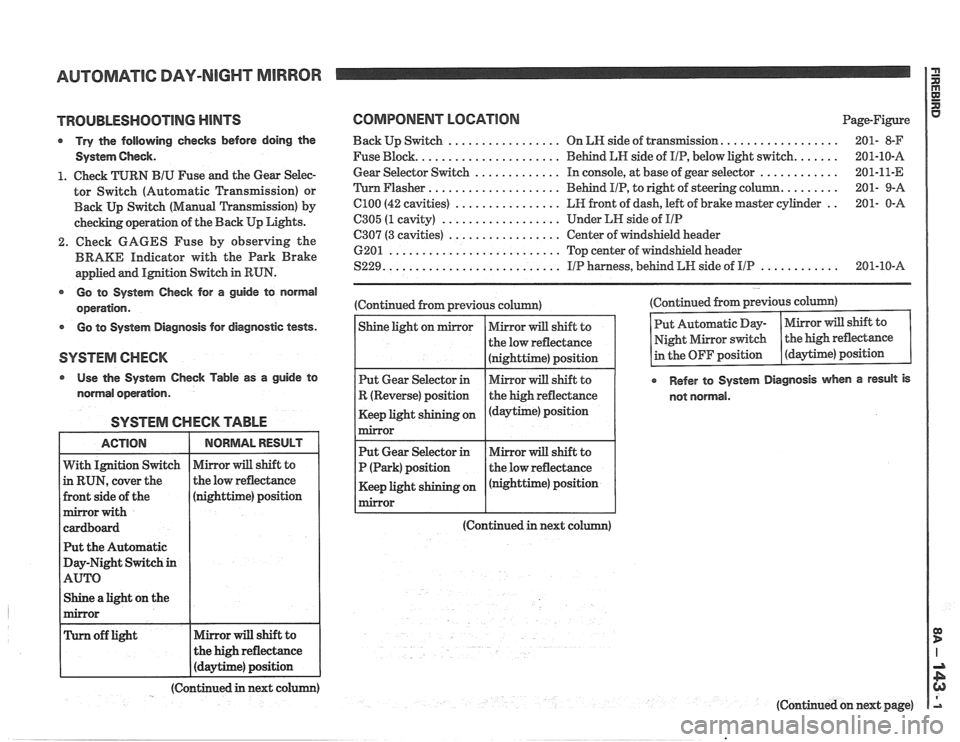
AUTOMATIC DAY-NIGHT MIRROR
TROUBLESHOOTING MINTS
Try the following checks before doing the
System
Gheck.
1. Check TURN BIU Fuse and the Gear Selec-
tor Switch (Automatic Transmission) or
Back
Up Switch (Manual 'L'ransfission) by
checking operation of the Back Up Lights.
2. Check GAGES Fuse by observing the
BRAKE Indicator with the Park Brake
applied and
IMtion Switch in RUN.
@ Go to System Gheck for a guide to normal
operation.
Go to System Diagnosis for diagnostic tests.
Use the System Check Table as a guide to
normal operation.
SYSTEM CHECK TABLE
nighttime) position
t the Automatic
ay-Night Switch
in
Shine a light on the
COMPONENT LOCATION Page-Figure
.................. Back Up Switch ................. On LN side of transIlnission 201- 8-F
...... Fuse Block. ..................... Behind LN side of IIP, below light switch. 201-10-A
............ Gear
Selector Switch ............. In console, at base of gear selector 201-11-E
........ 'Turn Flasher .................... Behind
PIP, to right of steering column. 201-
9-A
.. C100 (42 cavities) ................ LR front of dash, left of brake master cylinder 201-
0-A
6305 (1 cavity) .................. Under LH side of IIP
C307 (3 cavities) ................. Center of windshield header
6201
.......................... Top center of windshield header
............ S229. .......................... IIP harness, behind LW side of IIP 201-10-A
(Continued from previous column)
(Continued in next co (Continued
from previous column)
Refer to System Diagnosis when a result is
not normal.
(Continued in next colum)
(Continued on next page)
Page 1547 of 1825
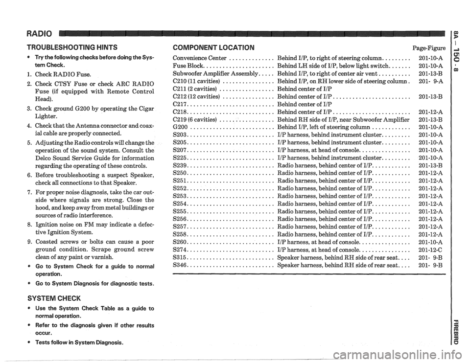
TROUBLESHOOTING HINTS
Try the following checks before doing the Sys-
tem Check
.
1 . Check RADIO Fuse .
2 . Check CTSU Fuse or check ARC RADIO
Fuse (if equipped with Remote Control
Head)
.
3 . Check ground 6200 by operating the Cigar
Lighter
.
4 . Check that the Antenna connector and coax-
ial cable are properly connected
.
5 . Adjusting the Radio controls will change the
operation of the sound system
. Consult the
Delco Sound Service Guide for information
regarding the operating of these controls
.
6 . Before troubleshooting a suspect Speaker,
cheek
all connections to that Speaker .
7 . For proper noise diagnosis. take the car out-
side where
signals are strong . Close the
hood. and keep away from metal buildings or
sources of radio interference
.
8 . Ignition noise on FM may indicate a defec-
tive Ignition System
.
9 . Coasted screws or bolts can cause a poor
ground condition
. Scrape ground screw
clean of any paint or varnish
.
Go to System Check for a guide to normal
operation
.
r Go to System Diagnosis for diagnostic tests .
SYSTEM CHECK
* Use the System Check Table as a guide to
normal operation
.
Refer to the diagnosis given if other results
occur
.
COMPONENT LOCATION Page-Figure
......... .............. Convenience Center Behind IIP. to right of steering column 201-10-A
....... Fuse Block ...................... Behind LH side of IIP. below light switch 201-10-A
.......... Subwoofer Amplifier Assembly ..... Behind IIP. to right of center air vent
201-13-B
. C210 (11 cavities) ................ Behind IIP. on RH lower side of steering column 201- 9-A
C211(2 cavities) ................. Behind center of IIP
........................ C212 (12 cavities) ................ Behind center of IIP 201-13-B
C217 ........................... Behind center of IIP
........................ C218 ........................... Behind center of IIP 201-12-A
C219 (6 cavities)
................. Behind RH side of IIP. near Subwoofer Amplifier 201-13-B
............ 6200 .......................... Behind IIP. left of steering column 201-10-A
......... $203 ........................... IIP harness. behind instrument cluster 201-10-A
......... $205 ........................... IIP harness. behind instrument cluster 201-10-A
................ $207 ........................... I/P harness. at head of console 201-10-A
......... S225 ........................... IIP harness. behind instrument cluster 201-10-A
............ $239 ........................... Radio harness. behind center of IIP 201-13-B
............ S250 ........................... Radio harness. behind center of I/P 201-12-A
............ $251 ........................... Radio harness. behind center of IIP 201-12-A
............ S252 ........................... Radio harness. behind center of IIP 201-12-A
............ S253 ........................... Radio harness. behind center of l[/P 201-12-8
............ $254 ........................... Radio harness. behind center of IIP 201-12-A
............ S255 ........................... Radio harness. behind center of I/P 201-12-A
............ ,9256 ........................... Radio harness. behind center of IIP 201-12-A
............ S257 ........................... Radio harness. behind center of IIP 201-12-A
............ S258 ........................... Radio harness. behind center of IIP 201-12-A
$260 ........................... IIP harness. at head of console ................ 201-10-A
................ S274 ........................... IIP harness. at head of console 201-12-C
$315 ........................... Speaker harness. behind RH side of rear seat .... 201- 9-B
.... $346 ........................... Speaker harness. behind RH side of rear seat 201- 9-B
Tests follow in System Diagnosis .
Page 1573 of 1825
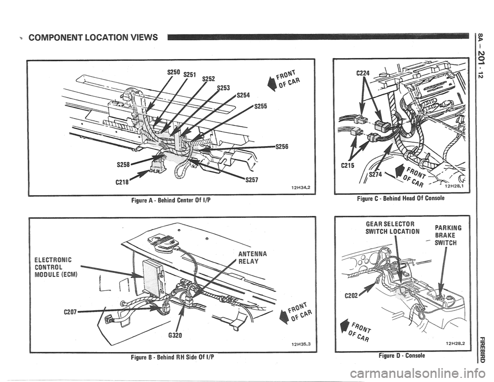
COMPONENT LOCATION VIEWS 1
Figure A - Behind Center Of IIP
EkEGTRONlC
CONTRhl h
MODULE (ECWIS)
Figure B - Behind RN Side Of IIP
SWITCH LBGATION BRAKE
Figure D - Console