1988 PONTIAC FIERO center console
[x] Cancel search: center consolePage 1609 of 1825
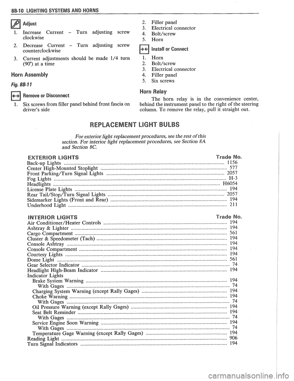
Adjust 2 . Filler panel 3 . Electrical connector
1 . Increase Current - Turn adjusting screw 4 . ~~l~/~~~~~
clockwise 5 . Horn
2 . Decrease Current . Turn adjusting screw
counterclockwise
Install or Connect
3 . Current adjustments should be made 1/4 turn
(90") at a time
Horn Assembly
Remove or Disconnect
1 . Six screws from filler panel behind front fascia on
driver's side 1
. Horn
2 . Bolt/screw
3 . Electrical connector
4
. Filler panel
5 . Six screws
Horn Relay
The horn relay is in the convenience center.
behind the instrument panel to the right of the steering
column
. To remove the relay. pull it straight out .
REPLACEMENT LIGHT BULBS
For exterior light replacement procedures. see the rest of this
section
. For interior light replacement procedures. see Section $A
and Section 8C .
EXTERIOR LIGHTS Trade No . ...................................................................................................................... Back-up Lights 1 156
Center
High-Mounted Stoplight ............................................................................................. 577
Front Barking/Turn Signal Eights ..................................................................................... 2057
Fog Lights
............................................................................................................................... H-3
Headlights ....................................................................................................................... H6054 ................................................................................................................ License Plate Lights 194
.................................................................................... Rear Tail/Stop/Turn Signal Lights 2057
Sidemarker Lights (Front and Rear) ...................................................................................... 194 ..................................................................................................................... Underhood Light 211
BNTERBOR LIGHTS Trade No .
......................................................................................... Air Conditioner/Heater Controls 194 .................................................................................................................. Ashtray & Lighter 194 .............................................................................................................. Cargo Compartment 561
................................................................................................ Cluster & Speedometer (Tach) 194 ..................................................................................................................... Console Ashtray 194 ............................................................................................................. Console Compartment 194
Courtesy Lights
..................................................................................................................... 194 ......................................................................................................................... Dome Light 561
Gear Selector Indicator
............................................................................................................ 74 .......................................................................................... Headlight High-Beam Indicator 194
Indicator Lights
..................................................................................................... Brake System Warning 194
With Gages
........................................................................................................................ 74
............................................................... Charging System Warning (except Rally Gages) 194 .................................................................................................................... Choke Warning
194
With Gages
........................................................................................................................ 74
...................................................................... Oil Pressure Warning (except Rally Gages) 194 ............................................................................................................ Seat Belt
Reminder 194
With Gages
.................................... ... ................................................................................. 74 ............................................................................................. Service Engine Soon Warning 194
With Gages
..................................................................................................................... 74 ............................................................ Temperature Gage Warning (except Rally Gages) 194
........................................................................................................................ Reading
Light 906 ............................................................................................................ Turn Signal Indicators 194
Page 1618 of 1825
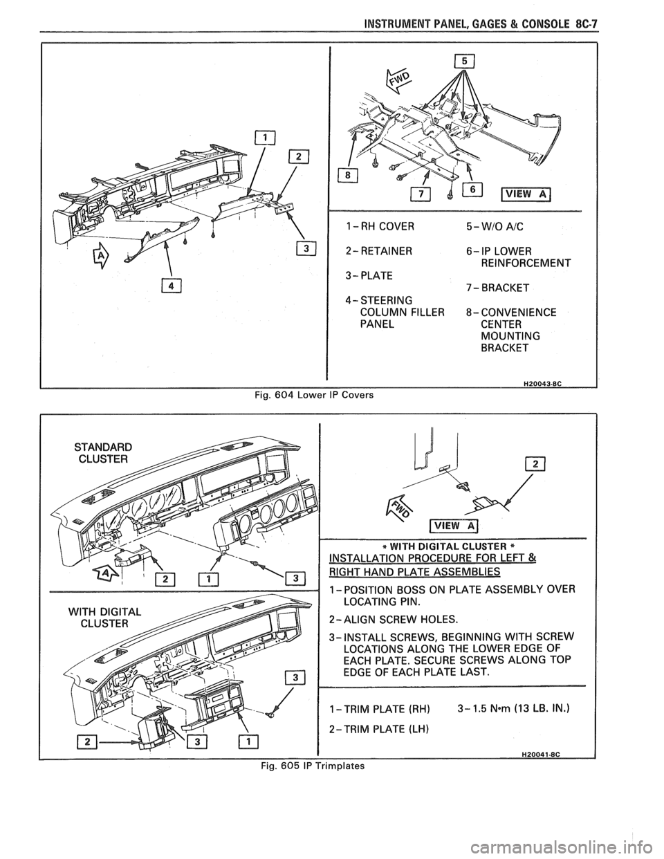
INSTRUMENT PANEL, GAGES & CONSOLE 86-7
1 - RH COVER 5 - WIO A/C
2- RETAINER 6- IP LOWER
REINFORCEMENT
3 - PLATE
7 - BRACKET
4- STEERING
COLUMN FILLER
8- CONVENIENCE
PANEL CENTER
MOUNTING
BRACKET
H20043-8C
Fig. 604 Lower IP Covers
Page 1624 of 1825
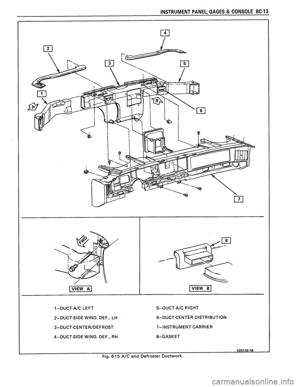
INSTRUMENT PANEL, GAGES & CONSOLE 8C-13
1 -DUCT-A/C LEFT
2-DUCT-SIDE WIND. DEF., LH
3-DUCT-CENTERIDEF ROST
4-DUCT-SIDE WIND. DEF., RH
5-DUCT-A/C RIGHT
6-DUCT-CENTER DISTRIBUTION
7-INSTRUMENT CARRIER
8-GASKET
Page 1707 of 1825
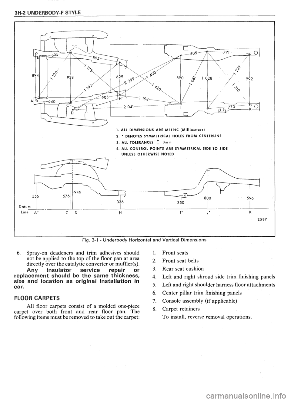
3H-2 UNDERBODY-F STYLE
Fig. 3-1 - Underbody Horizontal and Vertical Dimensions
6. Spray-on deadeners and trim adhesives should 1. Front seats
not be applied to the top of the floor pan at area
2, Front seat belts directly over the catalytic converter or muffler(s).
Any insulator service repair or 3. seat cushion
re~laeement should be the same thickness, 4. Left and right shroud side trim finishing panels size and location as original installation in
Car. 5. Left and right shoulder harness floor attachments
6. Center pillar trim finishing panels
FLOOR CARPETS 7. Console assembly (if applicable)
All floor carpets consist of a molded one-piece
*, Carpet retainers carpet over both front and rear floor pan. The
following items must be removed to take out the carpet: To
install, reverse removal operations.
Page 1760 of 1825
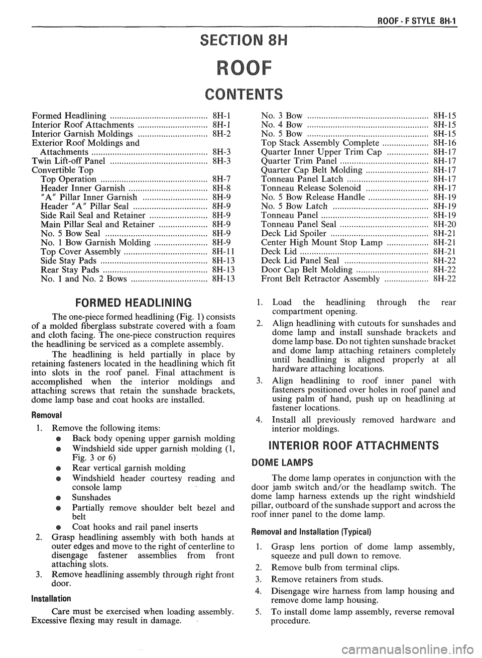
ROOF - F STYLE 8H-1
SECTION 8H
ROOF
CONTENTS
Formed Headlining .......................................... 8H- 1
Interior Roof Attachments
.............................. 8H- 1
Interior Garnish Moldings .............................. 8H-2
Exterior Roof Moldings and
Attachments
.................................... .... ... 8H-3
Twin Lift-off Panel
......................................... 8H-3
Convertible Top
Top Operation
............................................ 8H-7
Header Inner Garnish
................................. 8H-8
"A" Pillar Inner Garnish
........... .;. .............. 8H-9
Header
"A" Pillar Seal ................................ 8H-9
Side Rail Seal and Retainer
......................... 8H-9
Main Pillar Seal and Retainer
..................... 8H-9
No.
5 Bow Seal .......................................... 8H-9
No. 1 Bow Garnish Molding
....................... 8H-9
Top Cover Assembly
.................................... 8H- 1 1
Side Stay Pads ............................................. 8H-13
Rear Stay Pads ............................................ 8H- 13
No.
1 and No. 2 Bows ................................. 8H- 13 NO. 3
BOW
.................................................... 8H-15
NO. 4 BOW ................................................ 8H-15
NO. 5 BOW ................................................. 8H-15
Top Stack Assembly Complete .................... 8H- 16
Quarter Inner Upper Trim Cap
.................. 8H- 17
Quarter Trim Panel
.................................... 8H- 17
Quarter Cap Belt Molding
........................... 8H- 17
Tonneau Panel Latch
................................. 8H- 17
Tonneau Release Solenoid
........................... 8H- 17
No. 5 Bow Release Handle
.......................... 8H- 19
No.
5 Bow Latch ....................................... 8H-19
Tonneau Panel
.......................................... 8H- 19
Tonneau Panel Seal
............................. ......... 8H-20
Deck Lid Spoiler ........................................ 8H-2 1
Center High Mount Stop Lamp .................. 8H-21
Deck Lid .................................................... 8H-21
Deck Lid Panel Seal
................................. 8H-22
Door Cap Belt Molding ............................... 8H-22
Front Belt Retractor Assembly ................... 8H-22
FORMED HEADLINING 1. Load the headlining through the rear
The one-piece formed headlining (Fig. 1) consists
of a molded fiberglass substrate covered with a foam
and cloth facing. The one-piece construction requires
the headlining be serviced as a complete assembly.
The headlining is held partially in place by
retaining fasteners located in the headlining which fit
into slots in the roof panel. Final attachment is
accomplished when the interior moldings and
attaching screws that retain the sunshade brackets,
dome lamp base and coat hooks are installed.
Removal
1. Remove the following items:
e Back body opening upper garnish molding
r Windshield side upper garnish molding (1,
Fig. 3 or
6)
e Rear vertical garnish molding
a Windshield header courtesy reading and
console lamp
e Sunshades
e Partially remove shoulder belt bezel and
belt
a Coat hooks and rail panel inserts
2. Grasp headlining assembly with both hands at
outer edges and move to the right of centerline to
disengage fastener assemblies from front
attaching slots.
3. Remove headlining assembly through right front
door.
lnstallation
Care must be exercised when loading assembly.
Excessive flexing may result in damage. compartment
opening.
2. Align headlining with cutouts for sunshades and
dome lamp and install sunshade brackets and
dome lamp base. Do not tighten sunshade bracket
and dome lamp attaching retainers completely
until headlining is aligned properly at all
hardware attaching locations.
3. Align headlining to roof inner panel with
fasteners positioned over holes in roof panel and
using palm of hand, push up on headlining at
fastener locations.
4. Install all previously removed hardware and
interior moldings.
INTERIOR ROOF ATTACHMENTS
DOME LAMPS
The dome lamp operates in conjunction with the
door jamb switch and/or the
headlamp switch. The
dome lamp harness extends up the right windshield
pillar, outboard of the sunshade support and across the
roof inner panel to the dome lamp.
Removal and Installation (Typical)
1. Grasp lens portion of dome lamp assembly,
squeeze and pull down to remove.
2. Remove bulb from terminal clips.
3. Remove retainers from studs.
4. Disengage wire harness from lamp housing and
remove dome lamp housing.
5. To install dome lamp assembly, reverse removal
procedure.