1988 PONTIAC FIERO brake
[x] Cancel search: brakePage 126 of 1825
STEERING, SUSPENSION, f IRES AND WHEELS DIAGNOSIS 3.1
SECVION 3
STEER NG, SUSPENS
WHEELS
AGNOS
CONTENTS
........................................... General Information 3- 1 ............................................ General Diagnosis 3- 1
Power Recirculating Ball .................................. 3-3
................. Steering Linkage ........................ .. 3-3
Power Steering Pump ................... ... ............ 3-4
Steering Column
Lock System
........................... ... ................ 3-4
Column ............................................................ 3-5
........................................ Turn Signal Switch 3-6
Ignition Switch .............................................. 3-7
Key Reminder .............................................. 3-7
Dimmer Switch .................... ... ................ 3-10
Pivot and Switch Assembly ............................ 3-10
Steering Gear and Pump Leaks .......................... 3- 10
Seal Replacement Recommendations ................. 3- 10
Power Steering System Test Procedure .............. 3-12
................ Strut Dampener and Shock Absorber 3- 12
Tires ........................ .. ..................................... 3- 13
Vibrations .......................... .............. .................... 3- 14
.......................... Tapered Roller Bearings .. .... 3- 14
Trim Height .............................................. 3-14
GENERAL INFORMATION Abnormal or Excessive Tire Wear
Since the problems in steering, suspension, tires
and wheels involve several systems, they must all be
considered when diagnosing a complaint. To avoid
e Front-wheel or rear-wheel alignment
using the wrong symptom, always road test the car
o Sagging or broken springs
first. Proceed with the following preliminary checks
Tire out of balance and correct any substandard conditions which are worn strut dampener or shock absorber found. o Hard driving
--
e Tires for wrong pressure and uneven wear
o Joints from the column to the steering gear for
loose connectors or wear
o Front and rear suspension, and the steering gear
or linkage for loose or damaged parts
Out-of-round or out-of-balance tires, bent wheels,
and loose and/or rough wheel bearings
@ Power steering system for leaks. Also check the
power steering fluid level and the pump drive belt
tension
GENERAL DIAGNOSIS
Car Pulls (Leads)
Inspect
Mismatched or uneven tires
Broken or sagging springs
Radial tire lateral force
Front-wheel or rear-wheel alignment
o Steering gear valve off center (unbalanced)
e Front brakes dragging
a Overloaded car
e Not rotating tires
Scuffed Tires
o Toe incorrect
e Excessive speed on turns
o Suspension arm bent or twisted
Wheel Tramp
Inspect
o Blister or bump on tire
o Improper strut dampener or shock absorber
action
Shimmy, Shake or Vibration
inspect
e Tire or wheel out of balance
e Worn wheel bearings
a Worn tie rod ends
o Worn lower ball joints
Page 128 of 1825
STEERING, SUSPENSION, VIBES AND WHEELS DIAGNOSIS 3-3
Steering Wheel Kick-Back (Power)
Inspect
e Air in system
e Loose steering gear mounting
e Joints from column to steering gear loose or worn
e Tie rod ends loose
Worn or missing check valve
(800 series)
e Wheel bearings worn
e See "Too Much Play In Steering" for other
possible causes.
Steering Wheel Surges Or Jerks (Power)
Inspect
Hydraulic system - Make pressure test with gage
J 5176-D or
J 25323
e Sluggish steering gear valve
Loose pump drive belt
Cupped Tires
Inspect
Front-wheel or rear-wheel alignment
e Strut dampeners or shock absorbers weak
e Wheel bearing worn
e Excessive tire or wheel runout
e Worn ball joint
a Loose steering gear adjustment
POWER RECIRCULATING BALL
SEERING GEAR DIAGNOSIS
Hissing Noise
There is some noise in all power steering systems.
One of the most common is a hissing sound when the
steering wheel is turned and the car is not moving. This
noise will be most evident when turning the wheel
while the brakes are applied. There is no relationship
between this noise and steering performance. Do not
replace the valve unless the "hissing" noise is extremely
objectionable. A replacement valve will also have a
slight noise, and is not always a cure for the condition.
Check that the intermediate shaft joints are not loose.
Rattle or Chucking Noise
Inspect -
Pressure hose grounding out
e Tie rod ends loose
e Steering gear attachment loose
a Loose pitman shaft "over-center" adjustment.
A slight rattle may occur on turns because of
increased clearance off the "high point". This is
normal and clearance must not be reduced below
specified limits to eliminate this slight rattle.
Poor Return of Steering Wheel to Center
Front-wheel alignment
Wheel bearing worn
Tie rod end binding
Ball joint binding
Steering wheel rubbing against turn signal
housing
Steering gear adjustments
Tight or frozen intermediate steering shaft
Sticky or plugged spool valve
Momentary Increase in Effort Whsn Turning
Wheel Fast to Right or Left
Inspect
High internal leakage
Steering Wheel Surges or Jerks When Turning
With
Engine Running Especially During Parking
ln8pe~t
e Insufficient pump pressure
Sticky flow control valve
Excessive Wheel Kickback or Loose Steering
Air in system
Steering gear attachment loose
Tie rod ends loose
Wheel bearings worn
Steering gear flexible coupling loose on shaft or
rubber disc mounting nuts loose
Loose thrust bearing preload adjustment
Excessive "over-center" lash
Worn pressure port check valve
Hard Steering or Lack of Assist
(Especially During Parking)
-
Brakes applied while turning steering wheel
Intermediate shaft damaged or worn
e Sticky flow control valve
Insufficient pump pressure
Excessive internal pump leakage
Excessive internal steering gear leakage
STEERING LINKAGE DIAGNOSIS
Excessive Play or Looseness in Steering Systern
inspect
r, Worn upper ball joints
e Steering gear worm bearings loosely adjusted
Page 132 of 1825
STEERING, SUSPENSION, TIRES AND WHEELS DIAGNOSIS 3-7
e To determine if turn signal switch is inoperative,
substitute new turn signal switch into circuit and
operate switch by hand.
If the car's lights operate
normally, turn signal switch is inoperative.
Front Or Rear Turn Signal Lights Not Flashing
Inspect
s Burned-out or damaged turn signal bulb
e High resistance conection to ground at bulb
socket
s Loose chassis-to-column connector. Disconnect
column-to-chassis connector and connect new
turn signal switch into system and operate switch
by hand.
A. If turn signal lights are now on and flashing,
turn signal switch is inoperative.
B. If car lights do not operate, refer to Section
8A
for electrical diagnosis.
Turn Indicator Panel Lights
Inspect
Burned out bulbs or opens, grounds in the wiring
harness from the front turn signal bulb socket to the
indicator lights. Refer to Section
8A for electrical
diagnosis.
Stop Light Mot On When Turn Indicated
Inspect
s Loose column-to-chassis connection
e Disconnect the column-to-chassis connector and
connect the new turn signal switch into the
system and operate the switch by hand.
A. If the brake lights work when the switch is
in the turn position, the turn signal switch
is inoperative.
B. If the brake lights do not work, refer to Section
8A for electrical diagnosis.
Turn Signal Lights Flash Very Slowly
e Loose chassis-to-column connection
a Disconnect the column-to-chassis connector and
connect a new turn signal switch into the system
and operate the switch by hand.
A. If the lights flash at a normal rate, the turn
signal switch is inoperative.
B. If the Lights still flash very slowly, refer to
Section
8A for electrical diagnosis.
Hazard Signal Lights Will Not Flash - Turn
Signal Functions Normally
~"SPBC~
a Blown fuse
Inoperative hazard warning flasher
e Loose chassis-to-column connection
s Disconnect the column-to-chassis connector and
connect a new turn signal switch into the system,
then press in the hazard warning button and
watch the hazard warning lights.
A. If the lights now work normally, the turn
signal switch is inoperative.
B. If the lights do not flash, check the wiring
harness. Refer to Section
8A for electrical
diagnosis.
IGNITION SWITCH
Electrical System Will Not Function
Damaged ign~rion switch
e Ignition switch not adjusted properly
e Loose connector at the ignition switch
Switch Will Not Turn
Inspect
Damaged ignition switch
Switch Cannot Be Set Correctly
Inspect
Switch actuator rod deformed
e Sector to rack engaged in wrong tooth
KEY REMINDER
Figs. 1 through 11 ,
Weminder Continues To Operate With Key Out,
But Stops When Driver's Door Is Closed
e Chips, foreign material in lock cylinder bore
Sticky lock cylinder actuator tip
Damaged or broken reminder switch
Reminder Does Not Sound With Key Fully
Inserted In Lock Cylinder And The Driver's Door
Open
Inspect
1. Power not available to reminder. Refer to Sec-
tion
8A for electrical diagnosis.
2. Open in chassis wiring. Check by separating
chassis-to-column connector. Connect terminals
"E" and "F" female contacts on the chassis
connector (a bent paper clip will work). If the
reminder sounds, repair chassis wiring. If the
reminder does not sound, go to Step
A.
A. Connect a continuity meter (light) to the
male
"E" and "F" column connector
contacts. Push the key all the way into the
lock cylinder. If the light is on when the key
Page 139 of 1825
3-14 STEERING, SUSPENSION, TIRES AND WHEELS DIAGNOSIS
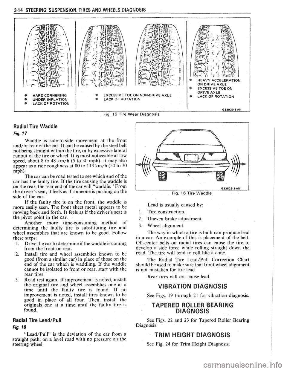
@ HARD CORNERING O UNDER INFLATION LACK OF ROTATION
@ HEAVY ACCELERATION ON DRIVE AXLE EXCESSIVE TOE ON DRIVE AXLE EXCESSIVE TOE ON NON-DRIVE AXLE @ LACK OF ROTATION O LACK. OF ROTAT ION
Fig. 15 Tire Wear Diagnosis
Radial Tire Waddle
Fig. 17
Waddle is side-to-side movement at the front
and/or rear of the car. It can be caused by the steel belt
not being straight within the tire, or by excessive lateral
runout of the tire or wheel. It ig most noticeable at low
speed, about 8 to 48
km/h (5 to 30 mph). It may also
appear as a ride roughness at 80 to 113
km/h (50 to 70
mph). The car can be road tested to see which end of the
car has the faulty tire. If the tire causing the waddle is
on the rear, the rear end of the car will "waddle." From
the driver's seat, it feels as if someone is pushing on the
side of the car.
If the faulty tire is on the front, the waddle is
more easily seen. The front sheet metal appears to be
moving back and forth. It feels as if the driver's seat is
the pivot point in the car.
Another more time-consuming method of
determining the faulty tire is substituting tire and
wheel assemblies that are known to be good. Follow
these steps:
1. Drive the car to determine if the waddle is coming
from the front or rear.
2. Install tire and wheel assemblies known to be
good (from a similar car) in place of those on the
end of the car which is waddling. If the waddle
cannot be isolated to front or rear, start with the
rear tires.
3. Road test again. If improvement is noted, install
the original tire and wheel assemblies one at a
time until the faulty tire is found. If no
improvement is noted, install tires known to be
good in place of all four. Then, install the
originals one at a time until the faulty tire is
found.
Radial Tire Lead/Pull
Fig. 18
"Lead/Pull" is the deviation of the car from a
straight path, on a level road with no pressure
on the
steering wheel.
L Fig. 16 Tire Waddle
Lead is usually caused by:
1. Tire construction.
2. Uneven brake adjustment.
3. Wheel alignment.
The way in which a tire is built can produce lead
in a car. An example of this is placement of the belt.
Off-center belts on radial tires can cause the tire to
develop a side force while rolling straight down the
road. The tire will tend to roll like a cone.
The Radial Tire
Lead/Pull Correction Chart
should be used to make sure that front wheel alignment
is not mistaken for tire lead.
Rear tires will not cause lead.
VIBRATION DIAGNOSIS
See Figs. 19 through 21 for vibration diagnosis.
TAPERED ROLLER BEARING
DlAGNOSlS
See Figs. 22 and 23 for Tapered Roller Bearing
Diagnosis.
See Fig. 24 for Trim Height Diagnosis.
Page 143 of 1825
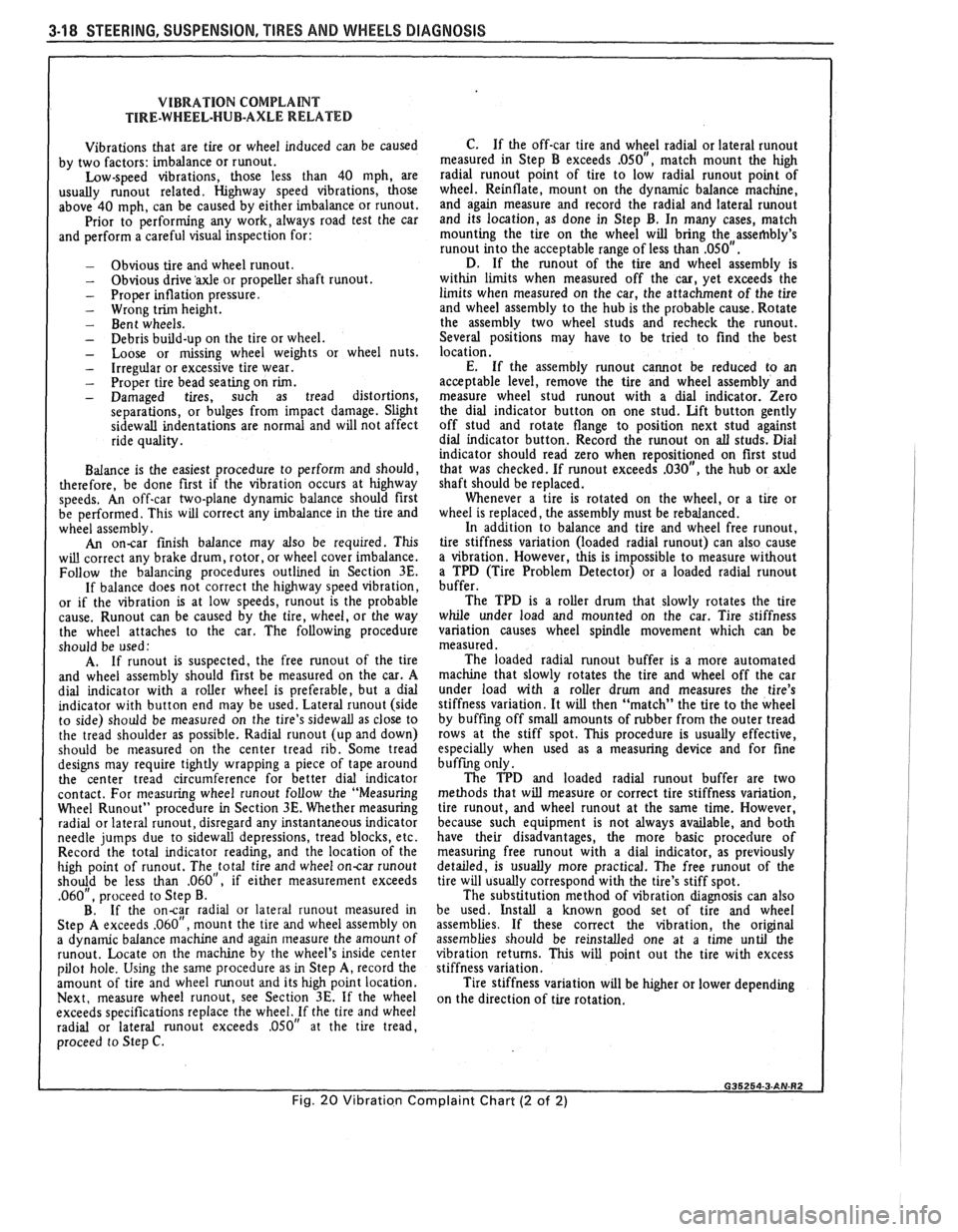
3-18 STEERING, SUSPENSION, TIRES AND WHEELS DIAGNOSIS
VIBRATION COMPLANT TIRE-WHEEL-HUB-AXLE RELATED
Vibrations that are tire or wheel induced can be caused
by two factors: imbalance or
runout. Low-speed vibrations, those less than 40 mph, are
usually runout related. Highway speed vibrations, those
above 40 mph, can be caused by either imbalance or runout. Prior to performing any work, always road test the car
and perform a careful visual inspection for:
- Obvious tire and wheel runout. - Obvious drive 'axle or propeller shaft runout. - Proper inflation pressure. - Wrong trim height. - Bent wheels. - Debris build-up on the tire or wheel. - Loose or missing wheel weights or wheel nuts. - Irregular or excessive tire wear. - Proper tire bead seating on rim. - Damaged tires, such as tread distortions,
separations, or bulges from impact damage. Slight sidewall indentations are normal and will not affect
ride quality.
Balance is the easiest procedure to perform and should,
therefore, be done fist if the vibration occurs at highway
speeds.
An off-car two-plane dynamic balance should first
be performed. This will correct any imbalance in the tire and
wheel assembly.
An oncar fiish balance may also be required. This will correct any brake drum, rotor, or wheel cover imbalance.
Follow the balancing procedures outlined in Section 3E. If balance does not correct the highway speed vibration,
or if the vibration is at low speeds, runout is the probable
cause. Runout can be caused by the tire, wheel, or the way
the wheel attaches to the car. The following procedure
should be used
: A. If runout is suspected, the free runout of the tire
and wheel assembly should first be measured on the car. A
dial indicator with a roller wheel is preferable, but a dial
indicator with button end may be used. Lateral
runout (side
to side) should be measured on the tire's sidewall as close to
the tread shoulder as possible. Radial
runout (up and down)
should be measured on the center tread rib. Some tread
designs may require tightly wrapping a piece of tape around
the center tread circumference for better dial indicator
contact. For measuring wheel
runout follow the "Measuring
Wheel Runout" procedure in Section 3E. Whether measuring
radial or lateral runout, disregard any instantaneous indicator
needle jumps due to sidewall depressions, tread blocks, etc.
Record the total indicator reading, and the location of the
high point of
runout. The,,total tire and wheel oncar runout should be less than ,060 , if either measurement exceeds ,060"~ proceed to Step B.
B. If
the oncy radial or lateral runout measured in
Step A exceeds .060 , mount the tire and wheel assembly on
a dynamic balance machine and again measure the amount of runout. Locate on the machine by the wheel's inside center
pilot hole. Using the same procedure as in Step A, record the
amount of tire and wheel
runout and its high point Location.
Next, measure wheel runout, see Section 3E. If the wheel
exceeds specifications replace the ~heel.,~If the tire and wheel
radial or lateral runout exceeds .050 at the tire tread,
proceed to Step C.
C. If the off-car tire and wheel radial or lateral runout measured in Step 18 exceeds .050", match mount the high radial runout point of tire to low radial runout point of
wheel. Weinflate, mount on the dynamic balance machine,
and again measure and record the radial and lateral runout and its location, as done in Step B. In many cases, match
mounting the tire on the wheel will bring the assembly's
runout into the acceptable range of less than .050". D. If the runout of the tire and wheel assembly is
within limits when measured off the car, yet exceeds the
limits when measured on the car, the attachment of the tire
and wheel assembly to the hub is the probable cause. Rotate
the assembly two wheel studs and recheck the
runout. Several positions may have to be tried to find the best
location.
E. If the assembly runout cannot be reduced to an
acceptable level, remove the tire and wheel assembly and
measure wheel stud
runout with a dial indicator. Zero
the dial indicator button on one stud. Lift button gently
off stud and rotate flange to position next stud against
dial indicator button. Record the
runout on all studs. Dial indicator should read zero when repositioned on first stud
that was checked. If runout exceeds .030", the hub or axle
shaft should be replaced.
Whenever a tire is rotated on the wheel, or a tire or
wheel is replaced, the assembly must be rebalanced.
In addition to balance and tire and wheel free
runout, tire stiffness variation (loaded radial runout) can also cause
a vibration. However, this is impossible to measure without
a TPD (Tire Problem Detector) or a loaded radial
runout buffer.
The TPD is a roller drum that slowly rotates the tire
while under load and mounted on the car. Tire stiffness
variation causes wheel spindle movement which can be
measured.
The loaded radial
runout buffer is a more automated
machine that slowly rotates the tire and wheel off the car
under load with a roller drum and measures the tire's
stiffness variation. It will then "match" the tire to the wheel
by buffing off small amounts of rubber from the outer tread
rows at the stiff spot. This procedure is usually effective,
especially when used
as a measuring device and for fine
buffing only.
The
TPD and loaded radial runout buffer are two
methods that will measure or correct tire stiffness variation,
tire
runout, and wheel runout at the same time. However,
because such equipment is not always available, and both
have their disadvantages, the more basic procedure of
measuring free
runout with a dial indicator, as previously
detailed, is usually more practical. The free runout of the
tire will usually correspond with the tire's stiff spot.
The substitution method of vibration diagnosis can also
be used. Install
a known good set of tire and wheel
assemblies. If these correct the vibration, the original
assemblies should be reinstalled one at
a time until the
vibration returns. This will point out the tire with excess
stiffness variation.
Tire stiffness variation will be higher or lower depending
on the direction of tire rotation.
Fig. 20 Vibration Complaint Chart (2 of 2)
Page 215 of 1825
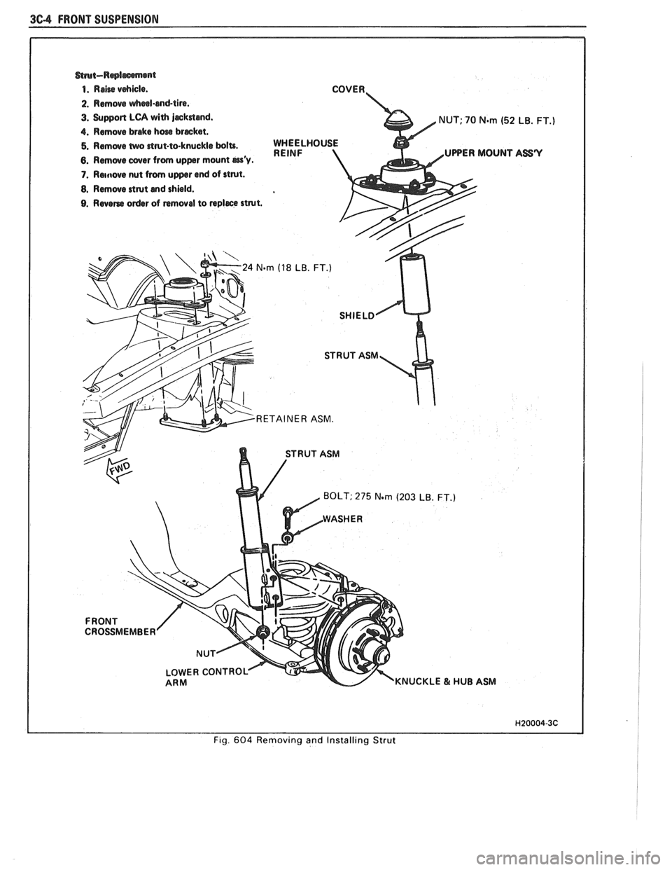
3C-4 FRONT SUSPENSION
3. Support LCA with j~kdmd. NUT; 70 Nern (52 LB. FT.)
4.
Remove brake hw brscket.
5. Remove tnro drut-to-knuckle bolts.
6. Remove cover from upper mount w'y. UPPER MOUNT ASS'V
7. Rmnove nut from upper end of strut.
8. Remove strut snd shield.
9. Revem order of removal to replece strut.
RETAINER ASM.
BOLT; 275 N.rn (203 LB. FT.)
CROSSMEMBER
LOWER CONTROL
KNUCKLE & HUB ASM
Fig. 604 Removing and Installing Strut I
Page 216 of 1825
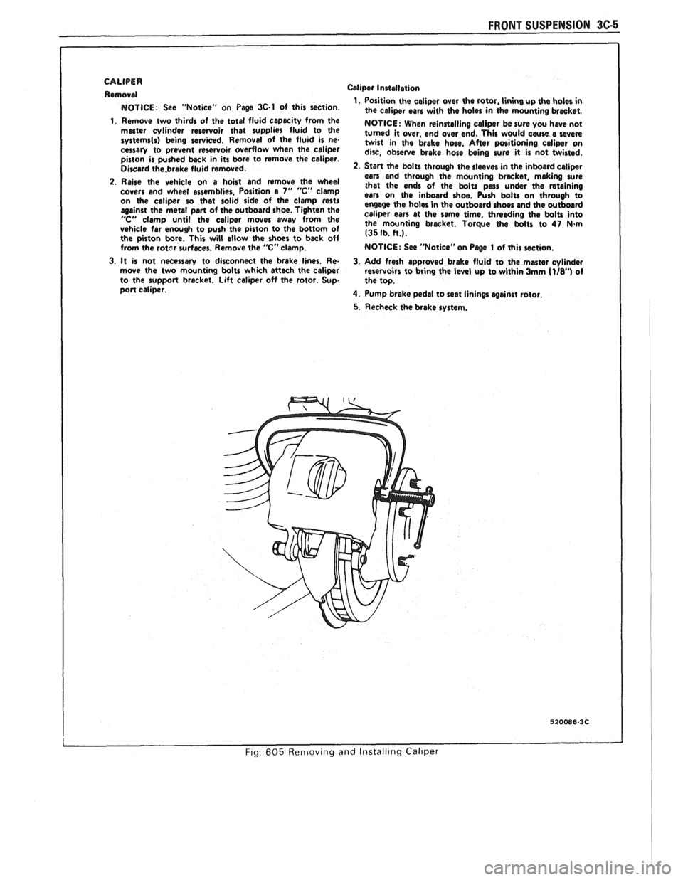
FRONT SUSPENSION 3C-5
CALIPER
Remowd
NOTICE: See "Notice" on Page 3C-1 of this section.
1. Remove two thirds of the total fluid capecity from the meter cylinder reservoir that supplies fluid to the rystemrls) baing ~~iCed. Removal of the fluid is ne-
cessary to prevent nservoir overflow when the caliper
piston is pushed back in its bore to remove the caliper. Dircard the.brake fluid removed.
2. Raise the vehicle on a hoist and rumove (he wheel
covers and wheel assemblies, Position a 7" "C" clamp
on the caliper ro that solid side of the clamp resu against the metal part of the outboard shoe. Tighten the "C" clamp until the caliper mwes away from the vehicle far enough to push the piston to the bottom of
the piston bore. This will allow the shoes to back off
from the
rotcr surfaces. Remove the "C" clamp.
Mipr Installation
1. Position the caliper over the rotor, lining up the holes in
the caliper can with the holes in (he mounting brmket.
NOTICE: When rsinrtalling calipsr bc sure you hwe not
turned it over, end over end. This would cause s even twist in the brake hose. After poritioning caliper on dirc, observe brake hose being sun it is not twisted.
2. Start (he bolts through the rlmves in the inboard caliper ears and through the mounting brmket, making sure
that the ends of the bolts pars under (he rstaining esn on the inboard ohm. Push bolts on through to
engage the holes in the outboard rhm and the outboard
caliper ears at the same time, thmrding the bolts into
the mounting brwket. Torque the bolts to 47 N-m (35 Ib. tt.).
NOTICE: See "Notice" on Psge 1 of this section.
3. It
is not necessary to disconnect the brake lines. Re-
3. Add fresh approved brake fluid to the master cylinder
rnwe the two mounting bolts which attach the caliper
reservoirs to bring the level up to within 3mm [I/&') ot
to the support bracket. Lift caliper off the rotor. Sup.
the top.
port caliper.
4. Pump brake pedal to seat linings
wainst rotor.
5. Recheck the brake system.
I I
FI~ 605 Ren~ov~ng and Iristalltrig Callper
Page 220 of 1825
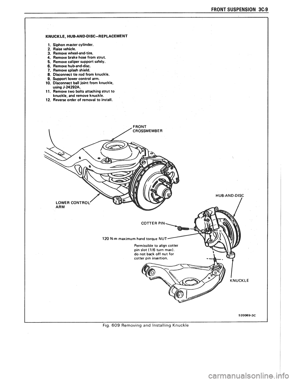
FRONT SUSPENSION 3C
KNUCKLE, HUBAND-DISC-REPLACEMENT
1. Siphon master cylinder.
2. Raise vehicle. 3. Remove wheel-and-tire. 4. Remove brake hose from strut. 5. Remove caliper support safely. 6. Remove huband-disc. 7. Remove splash shield. 8. Disconnect tie rod from knuckle. 9. Support lower control arm. 10. Disconnect ball joint from knuckle,
using J-24292A. 11. Remove two bolts attaching strut to
knuckle, and remove knuckle.
12. Reverse order of removal to install.
CROSSMEMBE R
LOWER CONTROL
ARM
COTTER PIN
120 N.m maximum hand torque NUT
Permissible to align cotter
pin slot
(1/6 turn max). do not back off nut for
cotter pln insert~on.
520089-3C
Fig. 609 Removing and Installing Knuckle