1988 PONTIAC FIERO brake
[x] Cancel search: brakePage 222 of 1825
REAR SUSPENSION 30.1
SECTION 3D
REAR SUSPENS
NOTICE: All rear suspension fasteners are important attaching parts in that they could affect the
performance of vital parts and systems, and/or could result in major repair expense. They must be replaced with
one of the same part number or with an equivalent part if replacement becomes necessary. Do not use
a
replacement part of lesser quality or substitute design. Torque values must be used as specified during reassembly
to assure proper retention of all parts. There is to be no welding as it may result in extensive damage and weakening
of the metal.
CONTENTS
General Information ................................ 3D- 1 Rear Lower Control Arm ............................ 3D-4
Qn-Car Service ............................ .. .......... 3D- 1 Bushing (Rear Lower Control Arm) ........... 3D-4
Shock Absorbers ........................................ 3D- 1 Torque Arm .............................................. 3D-5
Coil Springs and Insulators ......................... 3D- 1 Rear Stabilizer Shaft .................................. 3D-6
Track Bar ................................................... 3D-3 Bumper (Rubber) ....................................... 3D-6
Track Bar Brace ................... .. ................. 3D-3 Torque Specifications .................................. 3D-9
GENERAL INFORMATION
The rear axle assembly is attached to the vehicle
through a link type suspension system. The axle
housing is connected to the body by two lower control
arms and a track bar. A single torque arm is used in
place of upper control arms. It is rigidly mounted to the
rear axle housing at the rear and through a rubber
bushing to the transmission at the front. Coil springs
are used to support the weight of the car, and ride
control is provided by shock absorbers mounted to the
rear of the axle housing. A stabilizer shaft is optional.
The shock absorbers are mounted at the bottom
with a bolt and nut to brackets welded to the axle
housing, and at the top to the reinforced body area with
a nut. The only service the shock absorbers require is
replacement if they
have lost tllcir resistance, are
danaged, or are leaking flldd.
ON-CAR SERVICE
SI-IOCK ABSORBERS
Fig. 602
Remove or Disconnect
1. Hoist car and support rear axle.
2. From above, pull back carpeting and remove
shock absorber upper mounting nut.
NOTICE: Axle assembly must be supported
before removing upper shock absorber nut to avoid
possible damage to brake lines, track bar and prop
shaft.
3. Loosen and remove shock absorber lower
mounting nut from shock absorber. Remove
shock.
Install or Connect
NOTICE: See NOTICE on Page 3D-1 of this
section.
1. Position shock absorber through body mounting
hole and loosely install the lower shock absorber
mounting nut.
2. From above, install the upper shock absorber
retainer and nut. Torque nut.
3. Torque lower shock absorber nut.
4. Remove rear axle support and lower car.
COIL SPRINGS AND INSULATORS
Fig. 603
Remove or Disconnect
1. Hoist car on non twin post-type hoist and support
rear axle assembly with an adjustable lifting
device.
2. Track bar mounting bolt at axle assembly.
Loosen track bar bolt at body brace.
3. Rear brake hose clip at underbody to allow
additional axle drop.
4. Right and left shock absorber lower attaching
nuts.
5. Carefully lower rear axle and remove spring(s)
and or insulator(s).
NOTICE: DO NOT suspend rear axle by brake
hose. Damage to hose could result.
Install or Connect
NOTICE: See NOTICE on Page 3D-1 of this
section.
Page 224 of 1825
REAR SUSPENSION 30-3
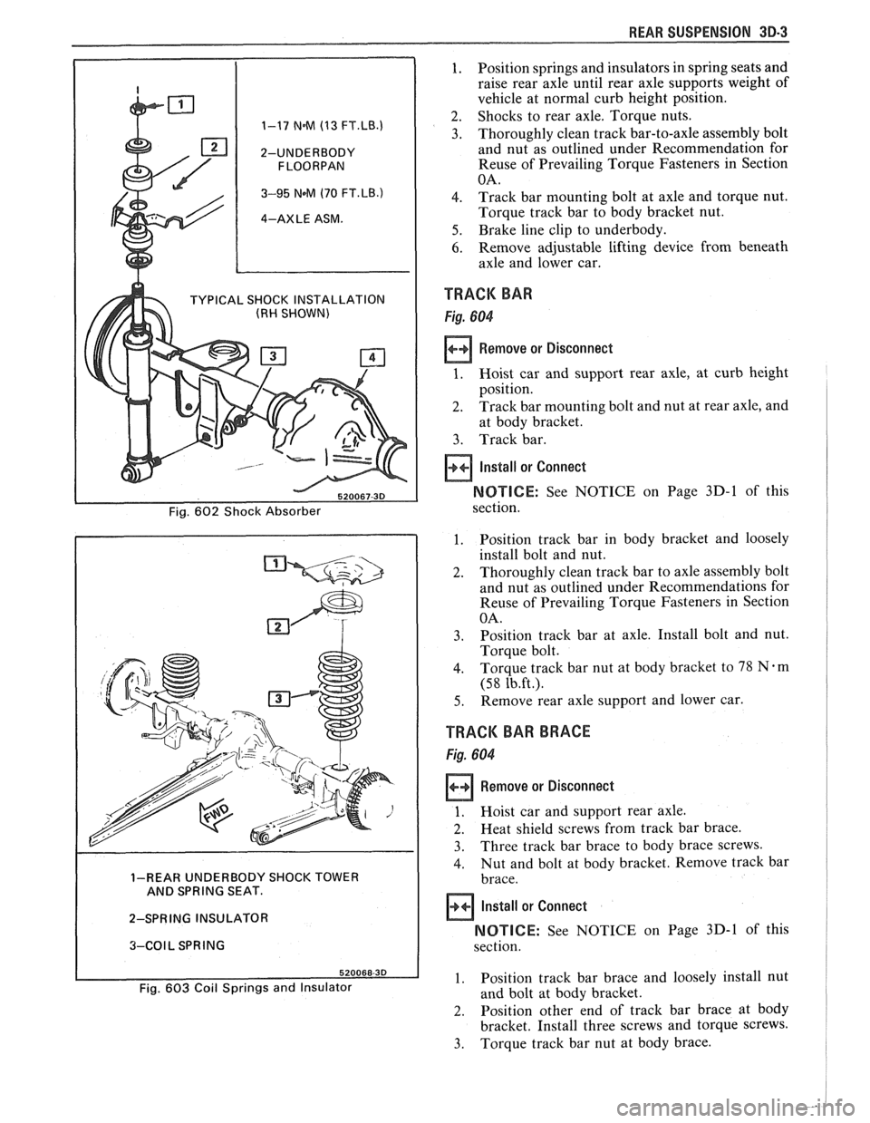
1. Position springs and insulators in spring seats and
raise rear axle until rear axle supports weight of
vehicle at normal curb height position.
2. Shocks to rear axle. Torque nuts. 1-17 N.M (13 FT.LB.1 3. Thoroughly clean track bar-to-axle assembly bolt
2-UNDERBODY and nut as outlined under Recommendation for
Reuse of Prevailing Torque Fasteners in Section
3-95 NeM (70 FT.LB.) 4. Track bar mounting bolt at axle and torque nut.
4-AXLE ASM. Torque track bar to body bracket nut.
5. Brake line clip to underbody.
6. Remove adjustable lifting device from beneath
axle and lower car.
TYPICAL SHOCK INSTALLATION TRACK BAR (RH SHOWN)
Remove or Disconnect
at body bracket.
3. Track bar.
Install or Connect
NOTICE: See NOTICE on Page 3D-1 of this
1. Position track bar in body bracket and loosely
install bolt and nut.
2. Thoroughly clean track bar to axle assembly bolt
and nut as outlined under Recommendations for
Reuse of Prevailing Torque Fasteners in Section
3. Position track bar at axle. Install bolt and nut.
4. Torque track bar nut at body bracket to 78 Nem
5. Remove rear axle support and lower car.
TRACK BAR BRACE
1. Hoist car and support rear axle.
2. Heat shield screws from track bar brace.
3. Three track bar brace to body brace screws.
4. Nut and bolt at body bracket. Remove track bar 1-REAR UNDERBODY SHOCK TOWER
AND SPRING SEAT.
2-SPRING INSULATOR
NOTICE: See NOTICE on Page 3D-1 of this 3-COIL SPRING
1. Position track bar brace and loosely install nut Fig. 603 Coil Springs and Insulator and bolt at body bracket.
2. Position other end of track bar brace at body
bracket. Install three screws and torque screws.
3. Torque track bar nut at body brace.
Page 226 of 1825
REAR SUSPENSION 3D-5
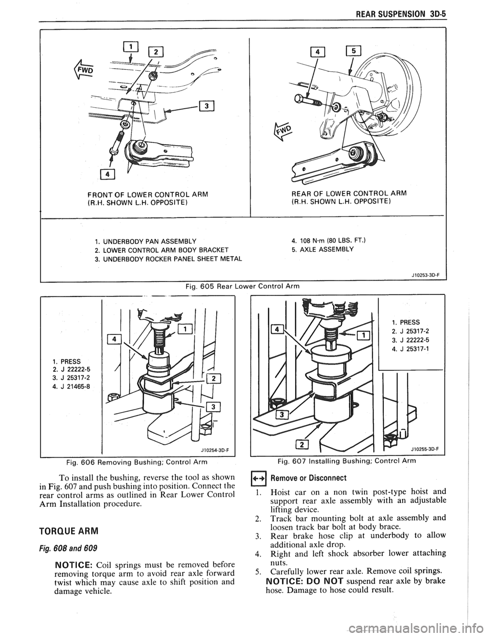
FRONT OF LOWER CONTROL ARM REAR OF
LOWER CONTROL ARM (R.W. SHOWN L.H. OPPOSITE) (R.H. SHOWN L.H. OPPOSITE)
1. UNDERBODY PAN ASSEMBLY 4. 108 N.rn (80 LBS. FT.)
2. LOWER CONTROL ARM BODY BRACKET 5. AXLE ASSEMBLY
3. UNDERBODY ROCKER PANEL SHEET METAL
Fig.
605 Rear Lower Control Arm
1. PRESS 2. J 22222-5
3.
J 25317-2
4.
J 21465-8
Fig. 606 Removing Bushing; Control Arm
To install the bushing, reverse the tool as shown
in Fig.
607 and push bushing into position. Connect the
rear control arms as outlined in Rear Lower Control
Arm Installation procedure.
TORQUE ARM
Fig. 608 and 609
NOTICE: Coil springs must be removed before
removing torque arm to avoid rear axle forward
twist which may cause axle to shift position and
damage vehicle.
1. PRESS
2. J 25317-2
3.
J 22222-5
4.
J 25317-1
I I Fig. 607 Installing Bushing; Contrcl Arm
Remove or Disconnect
1. Hoist car on a non twin post-type hoist and
support rear axle assembly with an adjustable
lifting device.
2. Track bar mounting bolt at axle assembly and
loosen track bar bolt at body brace.
3. Rear brake hose clip at underbody to allow
additional axle drop.
4. Right and left shock absorber lower attaching
nuts.
5. Carefully lower rear axle. Remove coil springs.
NOTICE: DO NOT suspend rear axle by brake
hose. Damage to hose could result.
Page 227 of 1825
30-8 WEAR SUSPENSION
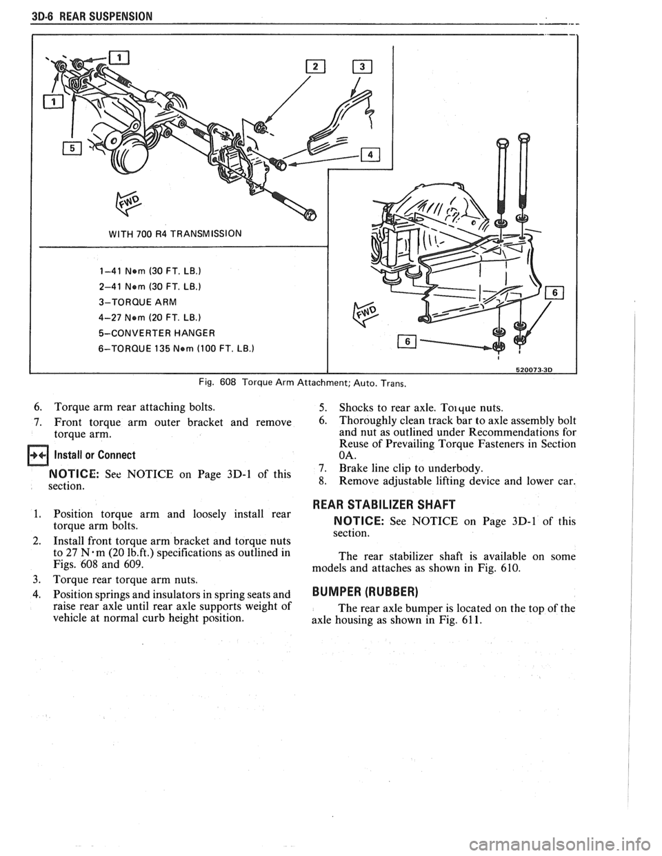
WITH 700 R4 TRANSMISSION
1-41 Nern (30 FT.
LB.)
2-41 Nern (30 FT. LB.)
3-TORQUE ARM
4-27 Nern
(20 FT. LB.)
5-CONVERTER HANGER
6-TORQUE 135
Nern (100 FT. LB.)
Fig. 608 Torque Arm Attachment; Auto. Trans.
6. Torque arm rear attaching bolts. 5. Shocks to rear axle. Toique nuts.
7. Front torque arm outer bracket and remove
6. Thoroughly clean track bar to axle assembly bolt
torque arm. and nut
as outlined under Recommendations for
Reuse of Prevailing Torque Fasteners in Section
Install or Connect OA.
7. Brake line clip to underbody. On Page 3D-1 of this 8. Remove adjustable lifting device and lower car.
section.
1. Position torque arm and loosely install rear
torque arm bolts.
2. Install front torque arm bracket and torque nuts
to 27
N.m (20 1b.ft.) specifications as outlined in
Figs.
608 and 609.
3.
Torque rear torque arm nuts.
4. Position springs and insulators in spring seats and
raise rear axle until rear axle supports weight of
vehicle at normal curb height position.
REAR STABILIZER SHAFT
NOTICE: See NOTICE on Page 3D-1 of this
section.
The rear stabilizer shaft is available on some
models and attaches as shown in Fig.
610.
BUMPER (RUBBER)
The rear axle bumper is located on the top of the
axle housing as shown in Fig.
61 1.
Page 233 of 1825
3E.2 TIRES AND WHEELS
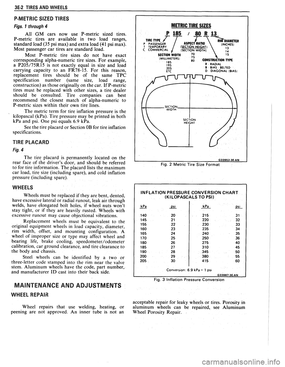
P-METRIC SIZED TIRES
Figs. 1 through 4
All GM cars now use P-metric sized tires.
P-metric tires are available in two load ranges,
standard load
(35 psi max) and extra load (41 psi max).
Most passenger car tires are standard load.
Most P-metric tire sizes do not have exact
corresponding alpha-numeric tire sizes. For example,
a
P205/75R15 is not exactly equal in size and load
carrying capacity to an
FR78-15. For this reason,
replacement tires should be of the same TPC
specification number (same size, load range,
construction) as those originally on the car. If P-metric
tires must be replaced with other sizes, a tire dealer
should be consulted. Tire companies can best
recommend the closest match of alpha-numeric to
P-metric sizes within their own tire lines.
The metric term for tire inflation pressure is the
kilopascal
(kPa). Tire pressure may be printed in both
kPa and psi. One psi equals 6.9 kPa.
See the tire placard or Section OB for tire inflation
specifications.
TlRE PLACARD
Fig. 4
The tire placard is permanently located on the
rear
face of the driver's door, and should be referred
to for tire information. The placard lists the maximum
car load, tire size (including spare), and cold inflation
pressure (including spare).
WHEELS
Wheels must be replaced if they are bent, dented,
have excessive lateral or radial
runout, leak air through
welds, have elongated bolt holes, if wheel nuts won't
stay tight, or if they are heavily rusted. Wheels with
excessive
runout may cause objectional vibrations.
Replacement wheels must be equivalent to the
original equipment wheels in load capacity, diameter,
rim width, offset, and mounting configuration.
A
wheel of improper size or type may affect wheel and
bearing life, brake cooling,
speedometer/odometer
calibration, car ground clearance, and tire clearance to
the body and chassis.
Steel wheels can be identified by a two or
three-letter code stamped into the rim near the valve
stem. Aluminum wheels have the code, part number,
and manufacturer
ID cast into their back side.
MAINTENANCE AND ADJUSTMENTS
WHEEL REPAIR
Wheel repairs that use welding, heating, or
peening are not approved. An inner tube is not an
Fig. 2 Metric Tire Size Format
INFLATION PRESSURE CONVERSION CHART (KI LOPASCALS TO PSI)
Fig. 3 Inflation Pressure Conversion
acceptable repair for leaky wheels or tires. Porosity in
aluminum wheels can be repaired, see Aluminum
Wheel Porosity Repair.
Page 235 of 1825
3E.4 TIRES AND WHEELS
TIRE CHAIN USAGE
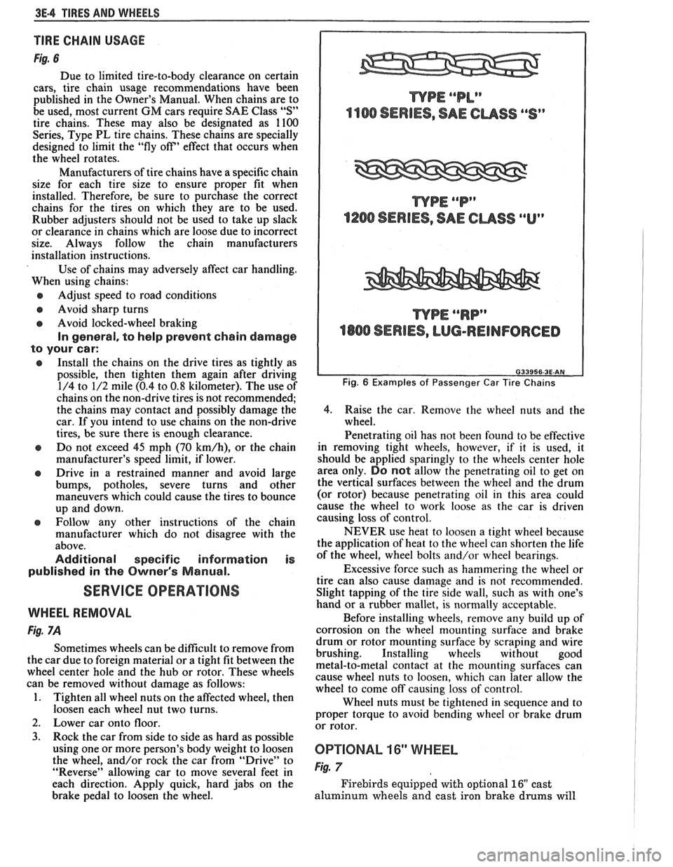
Fig. 6
Due to limited tire-to-body clearance on certain
cars, tire chain usage recommendations have been
published in the Owner's Manual. When chains are to
be used, most current
GM cars require SAE Class "S"
tire chains. These may also be designated as 1100
Series, Type PL tire chains. These chains are specially
designed to limit the "fly off' effect that occurs when
the wheel rotates.
Manufacturers of tire chains have a specific chain
size for each tire size to ensure proper fit when
installed. Therefore, be sure to purchase the correct
chains for the tires on which they are to be used.
Rubber adjusters should not be used to take up slack
or clearance in chains which are loose due to incorrect
size. Always follow the chain manufacturers
installation instructions.
Use of chains may adversely affect car handling.
When using chains:
@ Adjust speed to road conditions
@ Avoid sharp turns
@ Avoid locked-wheel braking
In general, to help prevent chain damage
to your car:
@ Install the chains on the drive tires as tightly as
possible, then tighten them again after driving
1/4 to 1/2 mile (0.4 to
0.8 kilometer). The use of
chains on the non-drive tires is not recommended;
the chains may contact and possibly damage the
car. If you intend to use chains on the non-drive
tires, be sure there is enough clearance.
e Do not exceed 45 mph (70 km/h), or the chain
manufacturer's speed limit, if lower.
@ Drive in a restrained manner and avoid large
bumps, potholes, severe turns and other
maneuvers which could cause the tires to bounce
up and down.
e Follow any other instructions of the chain
manufacturer which do not disagree with the
above.
Additional specific information is
published in the Owner's Manual.
SERVICE OPERATIONS
WHEEL REMOVAL
Fig. 7A
Sometimes wheels can be difficult to remove from
the car due to foreign material or a tight fit between the
wheel center hole and the hub or rotor. These wheels
can be removed without damage as follows:
1. Tighten all wheel nuts on the affected wheel, then
loosen each wheel nut two turns.
2. Lower car onto floor.
3. Rock the car from side to side as hard as possible
using one or more person's body weight to loosen
the wheel, and/or rock the car from
"Drive" to
"Reverse" allowing car to move several feet in
each direction. Apply quick, hard jabs on the
brake pedal to loosen the wheel.
WPE ""P"
1200 SERIES, SAE CUSS ""Up
WPE ""RP"
4800 SERIES, LUG-REINFORCED
Fig. 6 Examples of Passenger Car Tire Chains
4.
Raise the car. Remove the wheel nuts and the
wheel.
Penetrating oil has not been found to be effective
in removing tight wheels, however,
if it is used, it
should be applied sparingly to the wheels center hole
area only.
DO not allow the penetrating oil to get on
the vertical surfaces between the wheel and the drum
(or rotor) because penetrating oil in this area could
cause the wheel to work loose as the car is driven
causing loss of control.
NEVER use heat to loosen a tight wheel because
the application of heat to the wheel can shorten the life
of the wheel, wheel bolts and/or wheel bearings.
Excessive force such as hammering the wheel or
tire can also cause damage and is not recommended.
Slight tapping of the tire side wall, such as with one's
hand or a rubber mallet, is normally acceptable.
Before installing wheels, remove any build up of
corrosion on the wheel mounting surface and brake
drum or rotor mounting surface by scraping and wire
brushing. Installing wheels without good
metal-to-metal contact at the mounting surfaces can
cause wheel nuts to loosen, which can later allow the
wheel to come off causing loss of control.
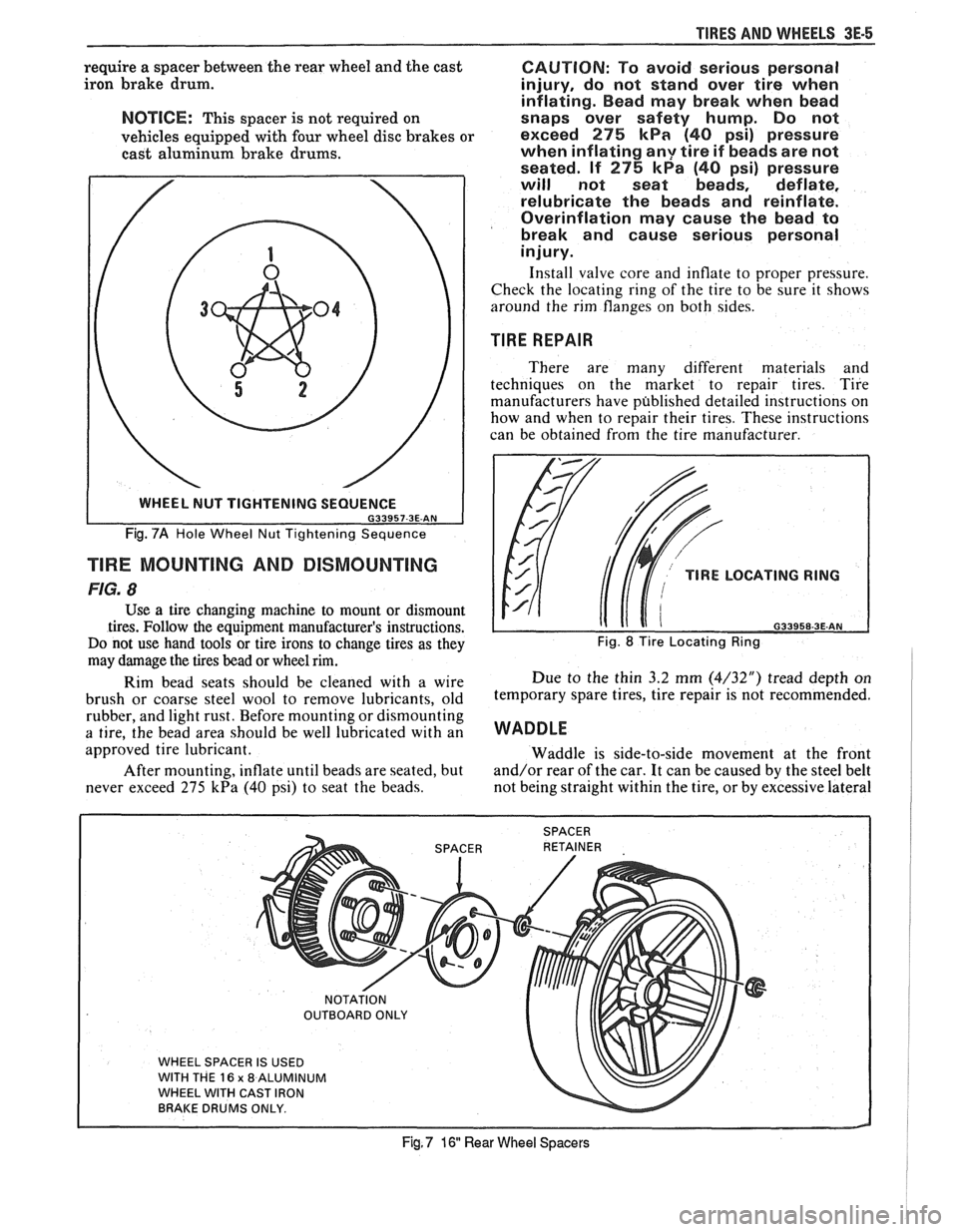
Wheel nuts must be tightened in sequence and to
proper torque to avoid bending wheel or brake drum
or rotor.
0P"FIONAL 16" WHEEL
Fig. 7
Firebirds equipped with optional 16" cast
aluminum wheels and cast iron brake
drums will
Page 236 of 1825
TIRES AND WI4EELS 3E-5
require a spacer between the rear wheel and the cast
iron brake drum.
NOTICE: This spacer is not required on
vehicles equipped with four wheel disc brakes or
cast aluminum brake drums.
Fig. 7A Hole Wheel Nut Tightening Sequence
TlRE MOUNTING AND DISMOUNTING
FIG. 8
Use a tire changing machine to mount or dismount
tires. Follow the equipment manufacturer's instructions.
Do not use hand tools or tire irons to change tires as they
may damage the tires bead or wheel rim.
Rim bead seats should be cleaned with a wire
brush or coarse steel wool to remove lubricants, old
rubber, and light rust. Before mounting or dismounting
a tire, the bead area should be well lubricated with an
approved tire lubricant.
After mounting, inflate until beads are seated, but
never exceed 275
kPa (40 psi) to seat the beads.
CAUTION: To avoid serious personal
injury, do not stand over tire when
inflating. Bead may break when bead
snaps over safety hump. Do not
exceed
275 kPa (40 psi) pressure
when inflating
any tire if beads are not
seated. If
275 kPa (40 psi) pressure
will not seat beads, deflate,
relubricate the beads and reinflate.
Overinflation may cause the bead to
break and cause serious personal
injury.
Install valve core and inflate to proper pressure.
Check the locating ring of the tire to be sure it shows
around the rim flanges on both sides.
TIRE REPAIR
There are many different materials and
techniques on the market to repair tires. Tire
manufacturers have published detailed instructions on
how and when to repair their tires. These instructions
can be obtained from the tire manufacturer.
TlRE LOCATING RING
naaaca a= AM
Fig. 8 Tire Locating Ring
Due to the thin 3.2 mm (4/32") tread depth on
temporary spare tires, tire repair is not recommended.
WADDLE
Waddle is side-to-side movement at the front
and/or rear of the car. It can be caused by the steel belt
not being straight within the tire, or by excessive lateral
WHEEL SPACER IS USED
WITH THE
16 x 8 ALUMINUM
WHEEL WITH CAST IRON
BRAKE DRUMS ONLY.
Fig, 7 16 Rear Wheel Spacers
Page 239 of 1825
3E-8 TIRES AND WHEELS
nearest the valve stem, and a 1/2 ounce balance weight
should be added 180" opposite the locking nut on the
wheel's inboard side.
When rotating tires, always re-install the locking
nut nearest the tire valve stem so that it remains
opposite the 1/2 ounce balance weight. This procedure
will improve the on-car wheel balance by compensating
for the heavy locking wheel nut.
Off-Car Balancing
Most electronic off-car balancers are more
accurate than the on-car spin balancers. They are easy
to use and give a dynamic (two plane) balance.
Although they do not correct for drum or rotor
unbalance as does on-car spin balancing, this is
overcome by their accuracy (usually to within 1/8
ounce). When balancing off-car, the wheel should
locate on the balancer with a cone through the back
side of the center pilot hole (not by the wheel stud
holes).
On-Car Balancing
When needed, on-car balancing will help correct
vibrations due to brake drum, rotor, and wheel cover
imbalance.
When balancing on car, do not remove the
balance weights from the off-car dynamic balance. If
more than one ounce of additional weight is required,
it should be split between the inner and outer rim
flange.
NOTICE: The driven tire and wheel assemblies
should be spun using the engine. Limit speed as
stated in the following Caution.
CAUTION: Do not spin the drive
wheels faster than
35 mph (55 km/h)
as indicated by the speedometer. This
limit is necessary because the
speedometer indicates only one-half
of the actual wheel speed when one
drive wheel is spinning and the other
drive wheel is stopped. Personal injury
and damage may result from high
speed spinning.
CAUTION: On cars equipped with
limited slip rear axles, do not attempt
to balance a tire on a
drive wheel with
the other drive wheel on the ground.
The car may drive through this wheel
and cause the car to move
unexpectedly, resulting in personal
injury and property damage.
To distinguish between standard rear axle and
limited slip, raise rear of car so both tires are clear of
ground. With the transmission in park (in gear with
manual transmission), attempt to turn one wheel by
hand. If the wheel can be turned, it is a standard rear
axle; if the wheel cannot be turned, it is a limited slip
rear axle. Also, check for Limited Slip
(G80) on Service
Parts Identification label.
Wheel Weights
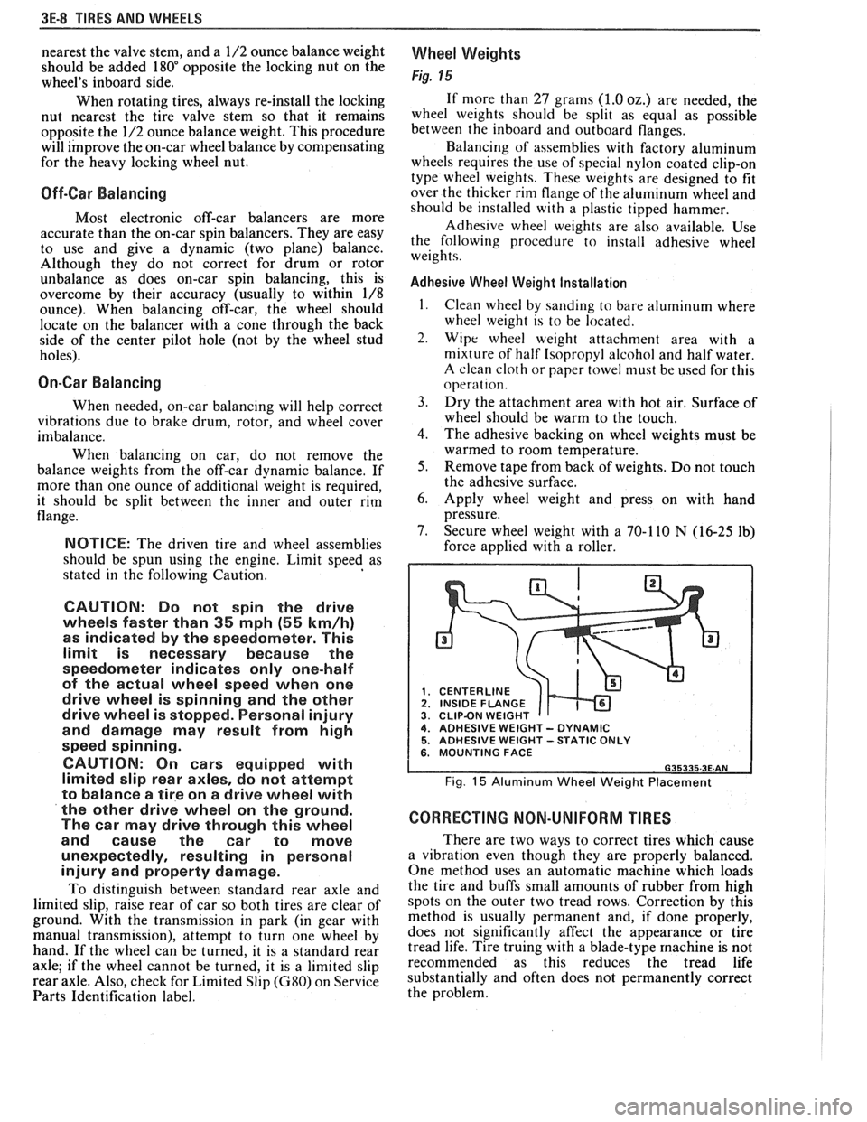
Fig. 15
If more than 27 grams (1.0 oz.) are needed, the
wheel weights should be split as equal as possible
between the inboard and outboard flanges.
Balancing of' assemblies with factory aluminum
wheels requires the use of special nylon coated clip-on
type wheel weights. These weights are designed to fit
over the thicker rim flange of the aluminum wheel and
should be installed with a plastic tipped hammer.
Adhesive wheel weights are also available. Use
the following procedure to install adhesive wheel
weights.
Adhesive Wheel Weight Installation
1. Clean wheel by sanding to bare aluminum where
wheel weight is to be located.
2. Wipe wheel weight attachment area with a
mixture of half Isopropyl alcohol and half water.
A clean cloth or paper towel niust be used for this
operat ion.
3. Dry the attachment area with hot air. Surface of
wheel should be warm to the touch.
4. The adhesive backing on wheel weights must be
warmed to room temperature.
5. Remove tape from back of weights. Do not touch
the adhesive surface.
6. Apply wheel weight and press on with hand
pressure.
7. Secure wheel weight with a 70-1 10
N (16-25 lb)
force applied with a roller.
CENTERLINE
1 INSIDE FLANGE CLIPBN WEIGHT 4. ADHESIVE WEIGHT - DYNAMIC 5. ADHESIVE WEIGHT -STATIC ONLY 6. MOUNTING FACE
Fig. 15 Aluminum Wheel Weight Placement
CORRECTING NON-UNIFORM TIRES
There are two ways to correct tires which cause
a vibration even though they are properly balanced.
One method uses an automatic machine which loads
the tire and buffs small amounts of rubber from high
spots on the outer two tread rows. Correction by this
method is usually permanent and, if done properly,
does not significantly affect the appearance or tire
tread life. Tire truing with a blade-type
machine is not
recommended as this reduces the tread life
substantially and often does not permanently correct
the problem.