1988 PONTIAC FIERO brake
[x] Cancel search: brakePage 285 of 1825
48-1 2 REAR AXLE
models it may be necessary to disconnect shock
absorbers to obtain additional clearance. When doing
this, do not allow the rear brake hose to become kinked
or stretched.
Lubricant may be drained by backing out all
cover bolts and breaking cover loose at the bottom.
If the rear axle housing is removed for any reason,
rear axle service can be performed on the bench.
When a new ring gear and pinion is installed, the
owner should be advised not to accelerate rapidly or
exceed
50 mph for the first 50 miles of driving.
Case Assembly
Remove or Disconnect
1. Before removing the rear axle case from the
housing, ring gear to drive pinion backlash
should be checked. This will indicate gear or
bearing wear or an error in backlash or preload
setting which will help in determining the cause
of axle noise.
2. Remove rear axle bearing cap bolts. Bearing caps
should be marked
"It" and "L" to make sure they
will be reassembled in their original location.
3. Remove rear axle case. Exercise caution in prying
on carrier so that gasket sealing surface is not
damaged. Place right and left bearing outer races
and shims in sets with marked bearing caps so
that they can be reinstalled in their original
positions.
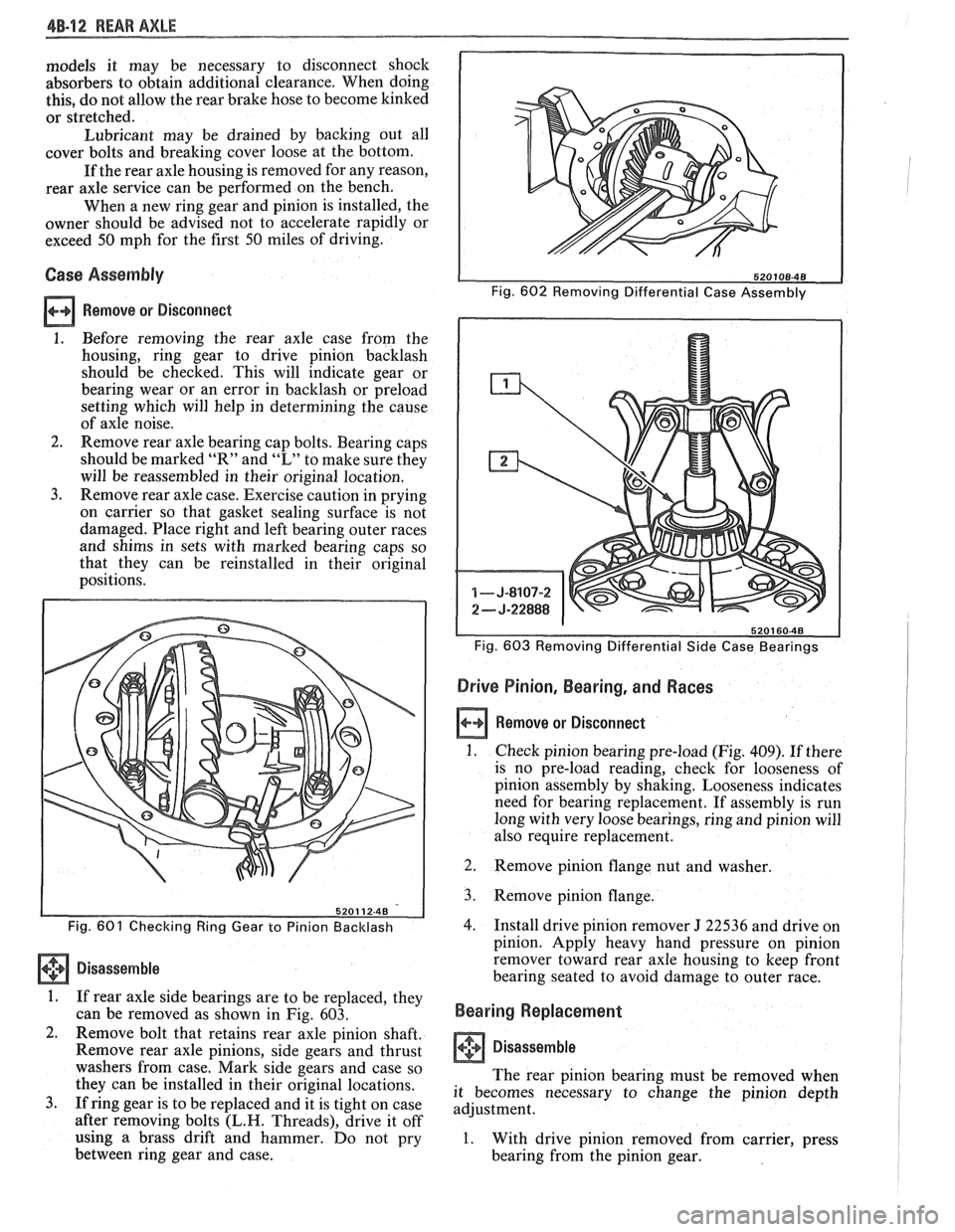
Fig. 603 Removing Differential Side Case Bearings
Drive Pinion, Bearing, and Races
a Remove or Disconnect
1. Check pinion bearing pre-load (Fig. 409). If there
is no pre-load reading, check for looseness of
pinion assembly by shaking. Looseness indicates
need for bearing replacement. If assembly is run
long with very loose bearings, ring and pinion will
also require replacement.
Fig. 601 Checking Ring Gear to Pinion Backlash
Disassemble
1. If rear axle side bearings are to be replaced, they
can be removed as shown in Fig. 603.
2. Remove bolt that retains rear axle pinion shaft.
Remove rear axle pinions, side gears and thrust
washers from case. Mark side gears and case so
they can be installed in their original locations.
3. If ring gear is to be replaced and it is tight on case
after removing bolts
(L.H. Threads), drive it off
using a brass drift and hammer. Do not pry
between ring gear and case. 2.
Remove pinion flange
nut and washer.
3. Remove pinion flange.
4. Install drive pinion remover J 22536 and drive on
pinion. Apply heavy hand pressure on pinion
remover toward rear axle housing to keep front
bearing seated to avoid damage to outer race.
Bearing Replacement
I Disassemble
The rear pinion bearing must be removed when
it becomes necessary to change the pinion depth
adjustment.
1. With drive pinion removed from carrier, press
bearing from the pinion gear.
Page 290 of 1825
REAR AXLE 48-1 7
approached. No further tightening should be
attempted until the pre-load has been checked.
7. Check pre-load by using an inch pound torque
wrench.
NOTICE: After pre-load has been checked, final
tightening should be done very carefully. For
example, if when checking, pre-load was found to
be 0.6
N-m (5 lbs. in.), any additional tightening
of the pinion nut can add many additional pound
inch of torque. Therefore, the pinion nut should be
further tightened only a little at a time and the
pre-load should be checked after each slight
amount of tightening. Exceeding pre-load
specifications will compress the collapsible spacer
too far and require the installation of a new
collapsible spacer.
While observing the preceeding note, carefully set
pre-load at 2.7 to 3.6
N-m (24 to 32 1b.in.) on new
bearings or 1.0 to 1.4
N m (8 to 12 1b.in.) on used
bearings.
8. Rotate pinion several times to assure that
bearings have been seated. Check pre-load again.
If pre-load has been reduced by rotating pinion,
reset pre-load to specifications.
Rear Axle Backlash Adjustment
1. Install rear axle case into carrier, using shims as
determined by the side bearing pre-load
adjustment.
2. Rotate rear axle case several times to seat
bearings, then mount dial indicator. Use a small
button on the indicator stem so that contact can
be made near heel end of tooth. Set dial indicator
so that stem is in line as nearly as possible with
gear rotation perpendicular to tooth angle for
accurate backlash reading.
3. Check backlash at three or four points around
ring gear. Lash must not vary over
.05mm (.002")
around ring gear. Pinion must be held stationary
when checking backlash. If variation is over
.05mm (.002") check for burrs, uneven bolting
conditions or distorted case flange and make
corrections as necessary.
4. Backlash at the point of minimum lash should be
between .13 and
.23mm (.005" and ,009") for all
new gears.
5. If backlash is not within specifications, correct by
increasing thickness of one shim and decreasing
thickness of other shim the same amount. This
will maintain correct rear axle side bearing
pre-load.
For each
.03mm (.001") change in backlash
desired, transfer
.05mm (.002") in shim
thickness. To decrease backlash
.03mm (.00lU),
decrease thickness of right shim .05mm (.002")
and increase thickness of left shim .05mm (.
002 "). To increase backlash .05mm (.002 ")
increase thickness of right shim .10mm (.004")
and decrease thickness of left shim .10mm (.
004"). 6.
When backlash is correctly adjusted, remove both
bearing caps and both shim packs.
Keep packs in their respective position, right or
left side.
Select a shim
.10mm (.004") thicker than the one
removed from the left side, then insert left side
shim pack between the spacer and the left bearing
race. Loosely install bearing cap.
7. Select a shim
.10mm (.004") thicker than the one
removed from right side and insert between the
spacer and the right bearing race. It will be
necessary to drive the right shim into position
(Fig. 614).
8. Torque to 75 Nem (55 1b.ft.).
9. Recheck backlash
and correct if necessary.
10. Install axles (See Rear Axle Installation).
11.
Use sealant 1052366 or cover gasket
only.
Install cover and torque cover bolts to 27
N-m (20 1b.ft.).
12. Fill rear axle to proper level with the specified
lubricant. Refer to specifications.
LIMITED SLIP REAR AXLE (GONE TYPE)
The cone-type limited-slip differential has several
definite operating characteristics. An understanding of
these characteristics is necessary as an aid to diagnosis.
The clutch energizing force comes from the
thrust side of the gears. Consequently, a free spinning
wheel may not have enough resistance to drive torque
to apply the clutch cones. If this occurs, apply the
parking brake a few notches which will provide enough
resistance to energize the clutch cones.
Energizing the clutch cones is independent of
acceleration; therefore, a very slow application of the
throttle on starting is recommended to provide
maximum traction by preventing "break away" of
either rear wheel.
Improper operation is generally indicated by cone
slippage or grabbing. Sometimes this produces a
chatter or whirring sound. However, these sounds do
not always indicate failure as they could be produced
from a lack of proper lubrication. For example, under
certain conditions where one wheel is on
a very slippery
surface and the other on dry pavement, wheel spin can
occur if over acceleration is attempted. Continued
spinning may cause audible noise, such as a whirring
sound, due to the cones lacking sufficient lubricant.
This does not necessarily indicate failure of the unit.
During regular operation (straight ahead driving)
when both wheels rotate at equal speeds, there is an
approximately equal driving force delivered to each
wheel. When cornering, the inside wheel delivers extra
driving force causing slippage in both clutch cones.
Consequently, the operational life of the limited slip
unit is dependent upon equal rotation of both wheels
during straight ahead operation. If wheel rotation for
both rear wheels is not equal during straight ahead
operation, the limited-slip unit will constantly be
functioning as if the vehicle were cornering. This will
impose constant slippage on the clutch cones and will
eventually lead to abnormal wear on the clutch cones.
Therefore, it is important that there be no excessive
differences in the rear wheel tire sizes, air pressures, or
Page 292 of 1825
REAR AXLE 48-19
RING NON US US GEAR WPQ RATIO BRAKES AXLE AXLE SIZE CODE CODE
GU2 2.73 ALUMINUM DRUM
6HE
GU2 2.73 CAST IRON DRUM 6HP
GU2 2.73 CAST IRON DRUM
6HT
7.625 G U4 3.08 CAST IRON DRUM 6HF
GU4 3.08 CAST IRON DRUM 6HK
G U4 3.08 ALUMINUM DRUM 6HB
GU6 3.42 CAST IRON DRUM 6HL
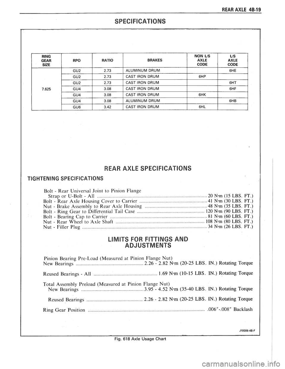
REAR AXLE SPEClFICAnONS
TIGHTENING SPECIFICATIONS
Bolt - Rear
Universal Joint to Pinion Flange
Strap or U-Bolt
- All ................................................................................ 20 Nem (15 LBS. FT.)
Bolt
- Rear Axle Housing Cover to Carrier ........................................... 41 N.m (30 LBS. FT.)
Nut
- Brake Assembly to Rear Axle Housing .......................................... 48 N-m (35 LBS. FT.)
Bolt
- Ring Gear to Differential Tail Case ............................................. 120 N.m (90 LBS. FT.)
Bolt
- Bearing Cap to Carrier ....................................................................... 81 N-m (60 LBS. FT.)
Nut
- Rear Wheel to Axle Shaft .................................................................. 108 N-m (80 LBS. FT.)
Nut
- Filler Plug ............................................................................................. 34 N-m (26 LBS. FT.)
LlMlTS FOR FI"TTINGS AND
ADJUSTMENTS
Pinion Bearing Pre-Load (Measured at Pinion Flange Nut)
New Bearings
................................................... 2.26 - 2.82 N-m (20-25 LBS. IN.) Rotating Torque
............................................. Reused Bearings - All 1.69 N-m (10-
15 LBS. IN.) Rotating Torque
Total Assembly Preload (Measured at Pinion Flange Nut)
New Bearings
.......................................... 3.95 - 4.52 N.m (35-40 LBS. IN.) Rotating Torque
.......................................... Reused Bearings 2.26 - 2.82 N.m (20-25 LBS. IN.)
Rotating Torque
Ring Gear Position
........................................................................................ .006"-.008" Backlash
Fig. 618 Axle Usage Chart
Page 294 of 1825
BRAKES
NOTICE: All brake attaching fasteners are important attaching parts in that they could affect the performance of vital parts
and systems.
andlor could result in major repair expense . They must be replaced with one of the same part number or with an
equivalent part if replacement becomes necessary
. Do not use a replacement part of lesser quality or substitute design .
Torque values must be used as specified during reassembly to assure proper retention of parts .
CAUTION: When servicing brake parts. do not create dust by grinding. sanding brake linings. or by cleaning brake
parts with a dry brush or with compressed air
. Many brake parts contain asbestos fibers which can become airborne if
dust is created during servicing
. Breathing dust containing asbestos fibers may cause serious bodily harm . A water
dampened cloth or water based solution should be used to remove any dust on brake parts
. Equipment is commer-
cially available to perform this washing function
. These wet methods will prevent asbestos fibers from becoming
airborne
.
CONTENTS
......................... General Description 5.2
Composite Master Cylinder
.................. 5.2
Brake Fluid Level
lndicatgr ................... 5.2
Operation of Disc Brake
..................... 5.2
Operation of Drum Brake
.................... 5.2
Operation of Combination Valve
............... 5.2
Brake Pressure Differential
.......................... Warning Switch 5.2
Diagnosis and Inspection ..................... 5.3
Brake System Testing
....................... 5.3
External Conditions That Affect Brake Performance
.................... -5-3
Warning Lamp Operation .................... 5.3
Brake Fluid Leaks
.......................... 5.3
Master Cylinder Check
...................... 5.3
Substandard or Contaminated
BrakeFluid ............................. 5-3
............................. On-Car Service 5.7
Brake Pedal Replacement
................... 5.7
Stoplamp Switch Adjustment ................. 5-7
Filling Master Cylinder Reservoirs
............. 5-7
Bleeding Brake Hydraulic System
............. 5.7
Manual Bleeding
......................... 5.8
Pressure Bleeding
........................ 5.8
Flushing Brake Hydraulic System
............. 5.9
Brake Pipe Replacement
.................... 5.9
............................. I.S.O. Flare 5.9
Brake Hose Inspection
...................... 5.9
Brake Hose Replacement
.................... 5.11
Front Brake Hose
........................ 5.11
....................... Center Brake Hose 5.12
..................... Rear Disc Brake Hose 5.12
ParkingBrake ............................. 5-13
Parking Brake Control Assembly
.............. 5.13 Parking Brake Cables
....................... 5.14
Parking Brake Front Cable
................. 5.14
Parking Brake Rear Cable (Drum Brakes)
..... 5.14
Parking Brake Rear Cable (Disc Brakes)
...... 5.15
Brake Lining Inspection
..................... 5.15
............. Inspecting and Refinishing Rotors 5-15
Thickness
Variat~on Check ................. 5.15
Lateral
Runout Check ..................... 5.15
Rotor Tolerance and Surface Finish
.......... 5.16
Refinishing Brake Rotors
.................. 5-16
lnspecting and Refinishing Brake
Drums
................................. 5-16
Cracked Scored, or Grooved Drum
.......... 5.16
Out-of-Round or Tapered Drum
............. 5.16
Refinishing Brake Drums
.................. 5.16
Brake Drum Balance
..................... -5-16
Combination Valve ......................... 5.17
Testing Combination Valve Electrical
............................... Circuit 5.17
Testing Combination Valve Warning
.......................... Lamp Switch 5.17
.......... Combination Valve Replacement 5.17
............ Power Brake Vacuum Hose Filter 5.17
Unit Repair
................ Composite Master Cylinder .5A 3.1
Disc Brake Caliper Assembly
....................... 300013100 Series 581 -1
Disc Brake Caliper Assembly
3548 Series
........................... .5B 6.1
........ Direct Torque Drum Brake Assembly .5C 3.1
Power Head Assembly
-
.................... Tandem Diaphragm .5D 2.1
.............. Specifications and Special Tools 5F-1
Page 295 of 1825
5-2 BRAKES
GENERAL DESCRIPTION
COMPOSIE EASTER CYLINDER
This vehicle uses a composite master cylinder which has
an aluminum body and a clear nylon reservoir with fluid
level indicators. The master cylinder uses a "quick take-up" feature in the
rear chamber to reduce pedal travel which may result from
increased fluid displacement required to move the caliper
piston. The quick take-up master cylinder includes a spring
loaded ball check valve which holds pressure in the
large-
diameter rear chamber. When the brake is first applied, the
movement of the rear piston causes fluid to be displaced
forward, past the primary piston primary seal and into the
primary high pressure chamber, which feeds the front
brakes. At a predetermined pressure, 480-690
kPa (70-100
mi), the ball unseats and fluid from the largi! rear bore is
disblaced past the ball and into the reservoir. The primary
and secondary high pressure chambers supply pressure to
the front and rear brakes, respectively, in the usual way.
When the pedal is released, the large-bore chamber is filled
with fluid by drawing fluid from the reservoir around the
quick take-up lip seal, and also through a small orifice in the
ball seat.
BRAKE FLUID LEVEL INDICATOR
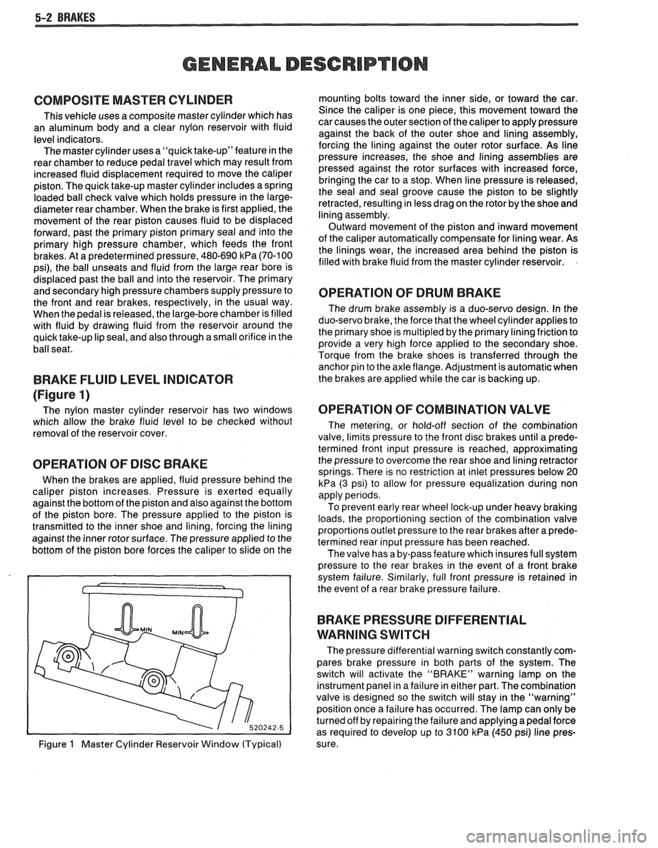
(Figure 1)
The nylon master cylinder reservoir has two windows
which allow the brake fluid level to be checked without
removal of the reservoir cover.
OPERATION OF DISC BRAKE
When the brakes are applied, fluid pressure behind the
caliper piston increases. Pressure is exerted equally
against the bottom of the piston and also against the bottom
of the piston bore. The pressure applied to the piston is
transmitted to the inner shoe and lining, forcing the lining
against the inner rotor surface. The pressure applied to the
bottom of the piston bore forces the caliper to slide on the
Figure
1 Master Cylinder Reservoir Window (Typical) mounting bolts toward the inner side,
or toward the car.
Since the caliper is one piece, this movement toward the
car causes the outer section of the caliper to apply pressure
against the back of the outer shoe and lining assembly,
forcing the lining against the outer rotor surface. As line
pressure increases, the shoe and lining assemblies are
pressed against the rotor surfaces with increased force,
bringing the car to a stop. When line pressure is released,
the seal and seal groove cause the piston to be slightly
retracted, resulting in less drag on the rotor by the shoe and
lining assembly.
Outward movement of the piston and inward movement
of the caliper automatically compensate for lining wear. As
the linings wear, the increased area behind the piston is
filled with brake fluid from the master cylinder reservoir.
OPERATION OF DRUM BRAKE
The drum brake assembly is a duo-servo design. In the
duo-servo brake, the force that the wheel cylinder applies to
the primary shoe is
multipled by the primary lining friction to
provide a very high force applied to the secondary shoe.
Torque from the brake shoes is transferred through the anchor pin to the axle flange. Adjustment is automatic when
the brakes are applied while the car is backing up.
OPERATION OF COMBINATION VALVE
The metering, or hold-off section of the combination
valve, limits pressure to the front disc brakes until a prede-
termined front input pressure is reached, approximating
the pressure to overcome the rear shoe and lining retractor
springs. There is no restriction at inlet pressures below 20
kPa (3 psi) to allow for pressure equalization during non
apply periods.
To prevent early rear wheel lock-up under heavy braking
loads, the proportioning section of the combination valve
proportions outlet pressure to the rear brakes after a prede-
termined rear input pressure has been reached.
The valve has a by-pass feature which insures full system
pressure to the rear brakes in the event of a front brake
system failure. Similarly, full front pressure is retained in
the event of a rear brake pressure failure.
BRAKE PRESSURE DIFFERENTIAL
WARNING
SWITCH
The pressure differential warning switch constantly com-
pares brake pressure in both parts of the system. The
switch will activate the "BRAKE" warning lamp on the
instrument panel in a failure in either part. The combination
valve is designed so the switch will stay in the "warning"
position once a failure has occurred. The lamp can only be
turned off by repairing the failure and applying a pedal force
as required to develop up to 3100
kPa (450 psi) line pres-
sure.
Page 296 of 1825
BRAKES 5-3
DIAGNOSIS AND INSPECTION
BRAKE SYSTEM TESTING
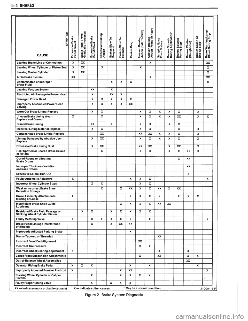
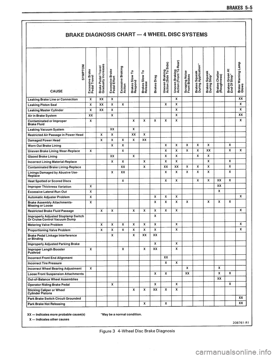
(Figures
2 through 4)
Brakes should be tested on dry, clean, reasonably
smooth and level roadway. A true test of brake performance
cannot be made if the roadway is wet, greasy or covered
with loose dirt so that all tires do not grip the road equally.
Testing will also be affected if the roadway is crowned
which would throw the weight of the car toward the wheels
on one side. If the roadway is too rough, the wheels will tend
to bounce. Test brakes at different car speeds with both light and
heavy pedal pressure, avoid locking the brakes and sliding
the tires. Locked brakes and sliding tires do not indicate
brake efficiency, because heavily braked, but turning
wheels will stop the car in less distance than locked brakes.
More tire-to-road friction is present with a heavily braked
turning tire than with a sliding tire. The brake system is designed and balanced to avoid
locking the wheels, except at very high deceleration levels.
The shortest stopping distance and best control is achieved
without brake lock-up.
Because of high deceleration capability, a firmer pedal
may be felt at higher deceleration levels.
External Conditions That Affect Brake Performance
1. Tires. Tires having unequal contact and grip on road
will cause unequal braking. Tires must be equally
inflated and tread pattern of right and left tires must
be approximately equal.
2. Car Loading. A heavily loaded car requires more
braking effort. When a car has unequal loading, the
most heavily loaded wheels require more braking
power than others.
3. Wheel Alignment. Misalignment of the wheels, par-
ticularly excessive camber and caster, will cause the
brakes to pull to one side.
4. Front Wheel Bearings. A loose front wheel bearing
BRAKE FLUID LEAKS
With engine running at idle and the transmission in neu-
tral, depress the brake pedal and hold a constant foot pres-
sure.
If the pedal gradually falls away with the constant
pressure, the hydraulic system may be leaking. Perform a
visual check to confirm any suspected leak.
Check the master cylinder fluid levels. While a slight drop
in reservoir level does result from normal lining wear, an
abnormally low level in either reservoir indicates
a leak in
the system. The hydraulic system may be leaking either
internally or externally. See "Master Cylinder Check."
Also, the system may appear to pass this test but still have
slight leakage.
If fluid levels are normal, check the vacuum booster
pushrod length. If an incorrect length pushrod is found,
adjust or replace the
pushrod. Check the service brake
pedal travel and the parking brake adjustment.
When checking the fluid levels, the master cylinder reser-
voir may be as low as
25 mm (1 inch) from the top if the front
linings are worn. This is not abnormal.
MASTER CYLINDER CHECK
These checks will help locate some master cylinder mal-
functions. Use the Brake Diagnosis Charts to help isolate
the problem if it is not found by using these tests.
1. Check for a cracked master cylinder casting or brake
fluid around the master cylinder. Leaks are indicated
only if there is at least a drop of fluid. A damp condi-
tion is not abnormal.
2. Check for a binding pedal linkage.
3. Disassemble the master cylinder and check for swol-
len or stretched piston
seal(s). If swollen seals are
found, substandard or contaminated brake fluid
should be suspected.
If contaminated, all compo-
nents should be disassembled and cleaned. All rub-
ber components should be replaced and all the pipes
should be flushed.
permits the front wheel to tilt and lose contact with the
SUBSTANDARD OR CONTAMINATED brake shoe linings causing erratic brake operation. BRAKE FLUID
WARNING LAMP OPERATION
The brake system uses a single red "BRAKE" warning
lamp located in the instrument panel cluster. When the
ignition switch is in the "START" position, the "BRAKE"
warning lamp should come on. It should go off when the
ignition switch returns to the "RUN" position.
The following conditions will activate the "BRAKE"
warning lamp:
1. Parking brake applied. The lamp should be on when
tfie parking brake is applied and the ignition switch is
"ON."
2. Pressure differential switch detects a failure. See
"Brake Pressure Differential Warning Switch" in this
section. Improper
brake fluid, mineral oil or water in the fluid may
cause the brake fluid to boil or the rubber components to
deteriorate.
If piston cups are swollen, the rubber parts have dete-
riorated. This deterioration may also be seen by swollen
wheel cylinder piston cups on the drum brake wheels or a
swollen master cylinder cover diaphragm.
If rubber deterioration is evident, disassemble all hydrau-
lic parts and wash with alcohol. Dry these parts with com-
pressed air before assembly to keep alcohol out of the
system. Replace all rubber parts in the system, including
hoses. Check for fluid on the linings. If excessive fluid is
found, replace the linings.
If master cylinder piston seals are satisfactory, check for
leakage or excessive heat conditions. If condition is not
found, drain fluid, flush with brake fluid, fill and bleed the
system.
Page 297 of 1825
5-4 BRAKES
Figure 2 Brake System Diagnosis
Page 298 of 1825
BRAKES 5-5
BRAKE DIAGNOSIS CHART - 4 WHEEL DISC SYSEEMS
XX - Indicates more probable cause(s) 'May be a normal condition.
X - Indicates other
Figure 3 4-Wheel Disc Brake Diagnosis