1988 PONTIAC FIERO ignition
[x] Cancel search: ignitionPage 561 of 1825
6EZ-C1-6 5.OL (VIN E) DRIVEABILITY AND EMISSIONS
A failure in the MAT sensor circuit should set a Code
23 or 25. The code charts also contain
a chart to check
for sensor resistance values relative to temperature.
MAP Sensor
A "ScanJ' tool reads manifold pressure and will
display either volts or
kPa of pressure.
Key "ONJ', engine stopped, (no vacuum), MAP will
read high voltage or pressure, while at idle
(highvacuum), MAP will read low voltage or pressure.
Likewise, on accel., MAP will read high and on decel.,
will read low.
A failure in the MAP sensor, or circuit, should
result in a Code 33 or 34.
Oxygen (02) Sensor
The "Scan" tool has several positions that will
indicate the state of the exhaust gases,
02 voltage,
integrator, and block learn. See "Scan" tool position
information in the Introduction of Section
"6E".
A problem in the O2 sensor circuit should set a
Code 13 (open circuit), Code
44 (lean 02 indication),
Code
45 (rich 02 indication). Refer to the applicable
chart, if any of these codes were stored in memory.
Throttle Position Sensor (TPS)
A "Scan" tool displays throttle position in volts.
The
5.OL should read under 1.25 volts, with throttle
closed and ignition on, or at idle. Voltage should
increase at a steady rate as throttle is moved toward
WOT. The ECM has the ability to Auto-Zero the TPS
voltage, if it is below about 1.25 volts. This means
that any voltage less than 1.25 volts volts will be
determined by the ECM to be
0% throttle. Some
"Scan" tools have the ability to read the percentage of
throttle angle and should read
0%, when the throttle
is closed.
A failure in the TPS circuit or TPS, should
set a Code 21 or 22.
Vehicle Speed Sensor (VSS)
A "Scan" tool reading should closely match with
speedometer reading, with drive wheels turning. A
failure in the VSS circuit should set a Code
24.
PIN Switch
A "Scan" tool should read "ON", when in park or
neutral and "OFF", when in drive. This reading may
vary with different makes of tools. Refer to CHART C-
IA for
PIN switch diagnosis.
Power steering Pressure Switch (POPS)
A Scan" tool should read "OFF" normally, and
"ON" with high pressure. This reading may vary with
different makes of tools. Refer to CHART
C-1E for
PSPS diagnosis.
NC Request Signal
If the low pressure switch is closed and AIC is
"ON", the "Scan" tool should indicate
A/C "ON".
Distributor Reference Signal
A "Scan" tool will read this signal and is displayed
in rpm. See Section
"C4", for more information on the
Ignition System
.
Knock Signal
A "Scan" tool will indicate when the ESC module
signals the ECM that knock is present. See Section
"C5" for further information on the ESC System.
ON-CAR SERVICE
ELECTRONIC CONTROL MODULE (ECM)
Service of the ECM should normally consist of
either replacement of the ECM or a PROM change.
If the diagnostic procedures call for the ECM to be
replaced, the engine calibrator (PROM) and ECM
should be checked first to see if they are the correct
parts. If they are, remove the PROM from the faulty
ECM and install it in the new service ECM. THE
SERVICE ECM
WILL NOT CONTAIN A PROM.
Trouble Code "51" indicates the PROM is installed
improperly or has malfunctioned. When Code "51" is
obtained, check the PROM installation for bent pins or
pins not fully seated in the socket. If the PROM is
installed correctly and Code
"51" still shows, replace
the PROM.
Important
When replacing the production ECM with a
service ECM (controller), it is important to
transfer the Broadcast code and production ECM
number to the service ECM label. Please do not
record on ECM cover. This will allow positive
identification of ECM parts throughout the service
life of the vehicle.
Page 562 of 1825
DRIVEABILITY AND EMISSIONS 5.OL (VIN E) 6EZ-C1-7
BRACKET
INSTRUMENT PANEL
(INSTRUMENT PANEL) '
MODULE ASM ECM (TBI)
BRACKET
1 BOLTISCREW (5) - 1 NUT (4) 4.7-7.0 N.rn (3.3-5.1 LBS. FT.)
NUT
BOLTISCREW (2) 2.2-3.4 N,rn (1.6-2.5 LBS. FT.)
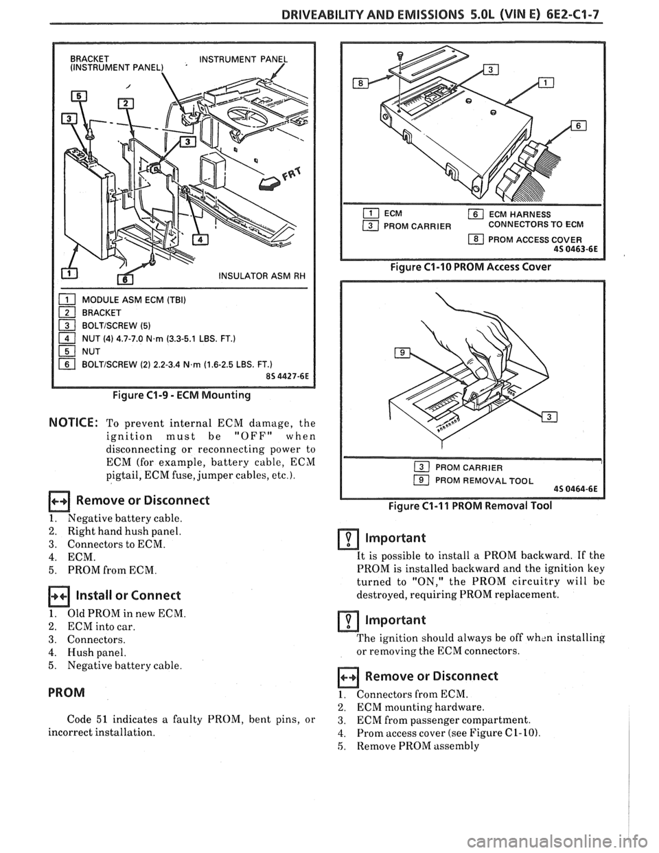
Figure C1-9 - ECM Mounting
NOTICE: To prevent internal ECM damage, the
ignition must be
"OFF" when
disconnecting or reconnecting power to
ECM (for example, battery cable, ECM
pigtail, ECM fuse, jumper cables,
etc.).
Remove or Disconnect
1. Negative battery cable.
2. Right hand hush panel.
3. Connectors to ECM.
4. ECM.
5. PROM from ECM.
Install or Connect
1. OldPROMinnewECM.
2. ECM into car.
3. Connectors.
4. Hush panel.
5. Negative battery cable.
PROM
Code 51 indicates a faulty PROM, bent pins, or
incorrect installation.
ECM HARNESS
PROM CARRIER CONNECTORS TO ECM
1 PROM ACCESS COVER 45 0463-6E
Figure C1-10 PROM Access Cover
1 PROM REMOVAL TOOL 45 0464-6E
Figure C1-I 1 PROM Removal Tool
Important
It is possible to install a PROM backward. If the
PROM is installed backward and the ignition key
turned to "ON," the PROM circuitry will bc
destroyed, requiring PROM replacement.
lmportant
The ignition should always be off wh~n installing
or removing the ECM connectors.
Remove or Disconnect
1. Connectors from ECM.
2. ECM mounting hardware.
3. ECM from passenger compartment.
4. Prom access cover (see Figure C 1- 10)
5, Remove PROM assembly
Page 563 of 1825
6E2-C1-8 5.OL (VIM E) DRIVEABILITY AND EMISSIONS
NOTCH IN PROM REFERENCED
TO SMALLER NOTCH IN
CARRIER AND THE PIN
#I END
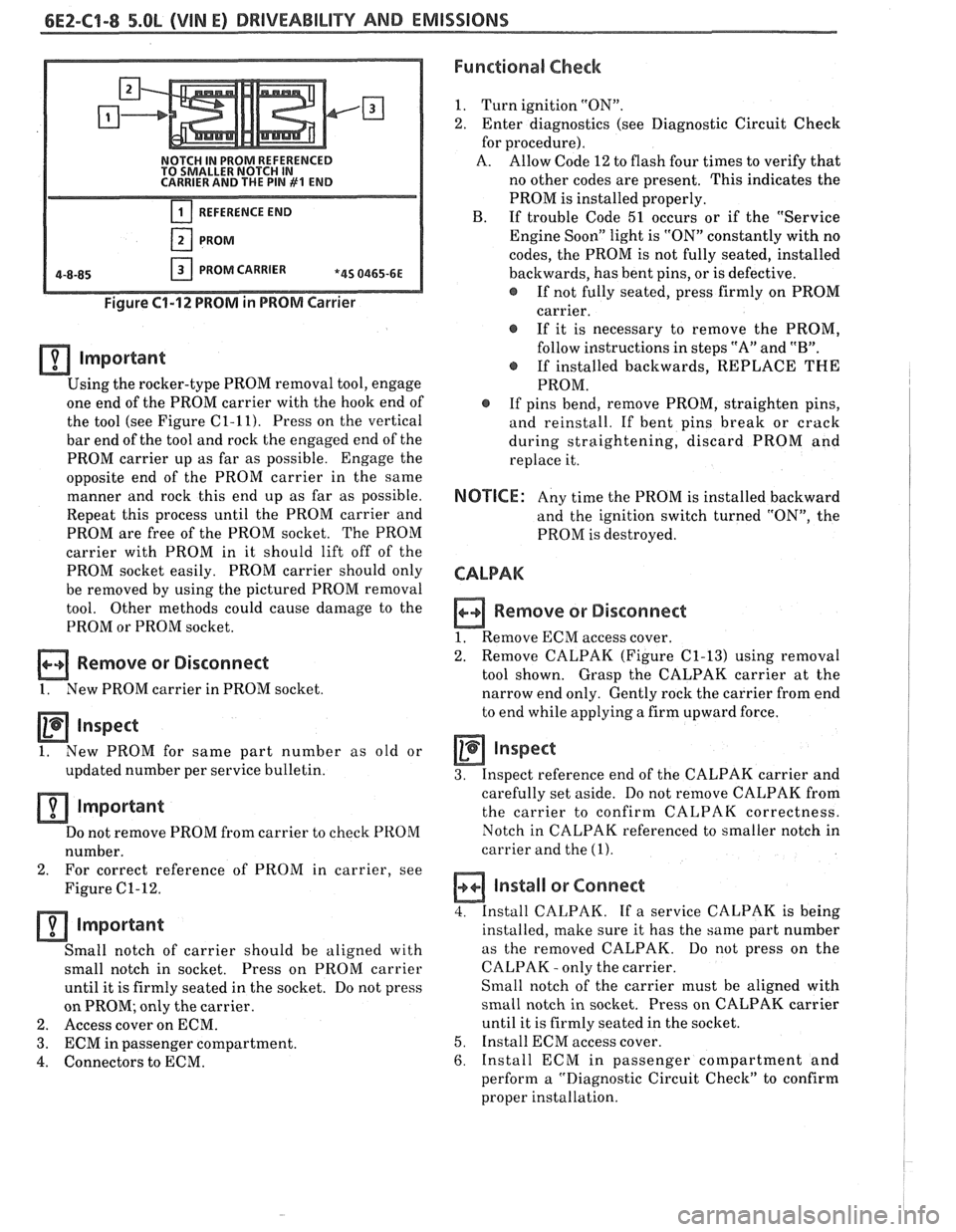
REFERENCE END
PROM
PROM CARRIER *4S 0465-6E
Figure 61-12 PROM in PROM Carrier
lmportant
Using the rocker-type PROM removal tool, engage
one end of the PROM carrier with the hook end of
the tool (see Figure
C1-11). Press on the vertical
bar end of the tool and rock the engaged end of the
PROM carrier up as far as possible. Engage the
opposite end of the PROM carrier in the same
manner and rock this end up as far as possible.
Repeat this process until the PROM carrier and
PROM are free of the PROM socket. The PROM
carrier with PROM in it should lift off of the
PROM socket easily. PROM carrier should only
be removed by using the pictured PROM removal
tool. Other methods could cause damage to the
PROM or PROM socket.
Remove or Disconnect
1. New PROM carrier in PROM socket
Inspect
1. New
PROM for same part number as old or
updated number per service bulletin.
Important
Do not remove PROM from carrier to check PROM
number.
2. For correct
reference of PROM in carrier, see
Figure
C1-12.
important
Small notch of carrier should be aligned with
small notch in socket. Press on
PROM carrier
until it is firmly seated in the socket. Do not press
on PROM; only the carrier.
2. Access cover on ECM.
3. ECM in passenger compartment.
4. Connectors to ECM.
Functional Check
1. Turn ignition "ON".
2. Enter diagnostics (see Diagnostic Circuit Check
for procedure).
A. Allow Code 12 to flash four times to verify that
no other codes are present. This indicates the
PROM is installed properly.
B. If trouble Code 51 occurs or if the "Service
Engine Soon" light is "ON" constantly with no
codes, the PROM is not fully seated, installed
backwards, has bent pins, or is defective.
@ If not fully seated, press firmly on PROM
carrier.
If it is necessary to remove the PROM,
follow instructions in steps "A" and
"B".
@ If installed backwards, REPLACE THE
PROM.
@ If pins bend, remove PROM, straighten pins,
and reinstall. If bent pins break or crack
during straightening, discard PROM and
replace it.
NOTICE: Any time the PROM is installed backward
and the ignition switch turned "ON", the
PROM is destroyed.
CALPAK
n Remove or Disconnect
1. Remove ECM access cover.
2. Remove
CALPAK (Figure
C1-13) using removal
tool shown. Grasp the CALPAK carrier at the
narrow end only. Gently rock the carrier from end
to end while applying a firm upward force.
Inspect
3. Inspect reference end of the CALPAK carrier and
carefully set aside. Do not remove CALPAK from
the carrier to confirm CALPAK correctness.
Notch in CALPAK referenced to smaller notch in
carrier and the
(1).
a Install or Connect
4. Install CALPAK. If a service CALPAK is being
installed, make sure it has the same part number
as the removed CALPAK. Do
not press on the
CALPAK
- only the carrier.
Small notch of the carrier must be aligned with
small notch in socket. Press on CALPAK carrier
until it is firmly seated in the socket.
5. Install ECM access cover.
6. Install ECM in passenger compartment and
perform a "Diagnostic Circuit Check" to confirm
proper installation.
Page 567 of 1825
6E2-C1-12 DRlVEABlLllV AND EMISSIONS - 5.OL (VIN E)
434 ORNIBLK
450 BLWHT
ENGINE GROUND
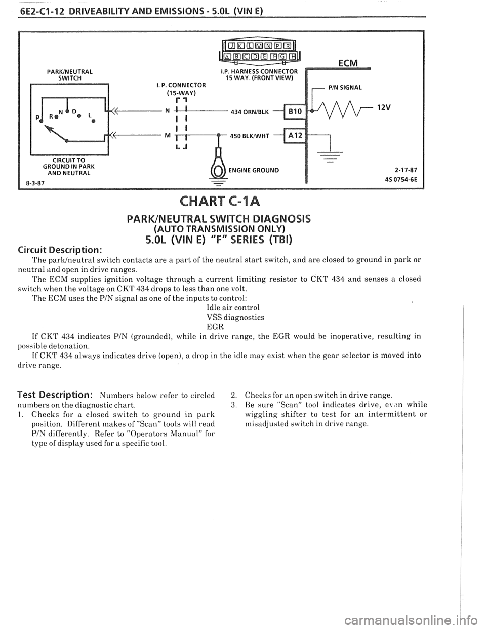
CHART C-lA
PARWNEUTRAL SWIKC DIAGNOSIS
(AUTO TRANSMISSION ONLY)
5.0L (VIN E) ""FYmSERIES (TBI)
Circuit Description:
The parklneutral switch contacts are a part of the neutral start switch, and are closed to ground in park or
neutral and open in drive ranges.
The ECM supplies ignition voltage through a current limiting resistor to CKT 434 and senses a closed
switch when the voltage on CKT
434 drops to less than one volt.
The ECM uses the PIN signal as one of the inputs to control:
Idle air control
VSS diagnostics
EGR
If CKT
434 indicates PIN (grounded), while in drive range, the EGR would be inoperative, resulting in
possible detonation.
If CKT
434 always indicates drive (open), a drop in the idle may exist when the gear selector is moved into
drive range.
Test Description: Numbers below refer to circled 2. Checks for an open switch in drive range.
numbers on the diagnostic chart.
3. Be sure "Scan" tool indicates drive, el ,tn while
I. Checks for a closed switch to ground in park wiggling
shifter to test for an intermittent or
position.
Iliffercnt lrlakes of "Scan" tools will rend ~nisadjusted switch in drive range.
PIS differently. Refer to "Operators Slanuul" for
type of display used for a specific tool.
Page 571 of 1825
6EZ-C1-16 DRIVEABILITY AND EMISSIONS - 5.OL (VIN E)
MAP SIGNAL
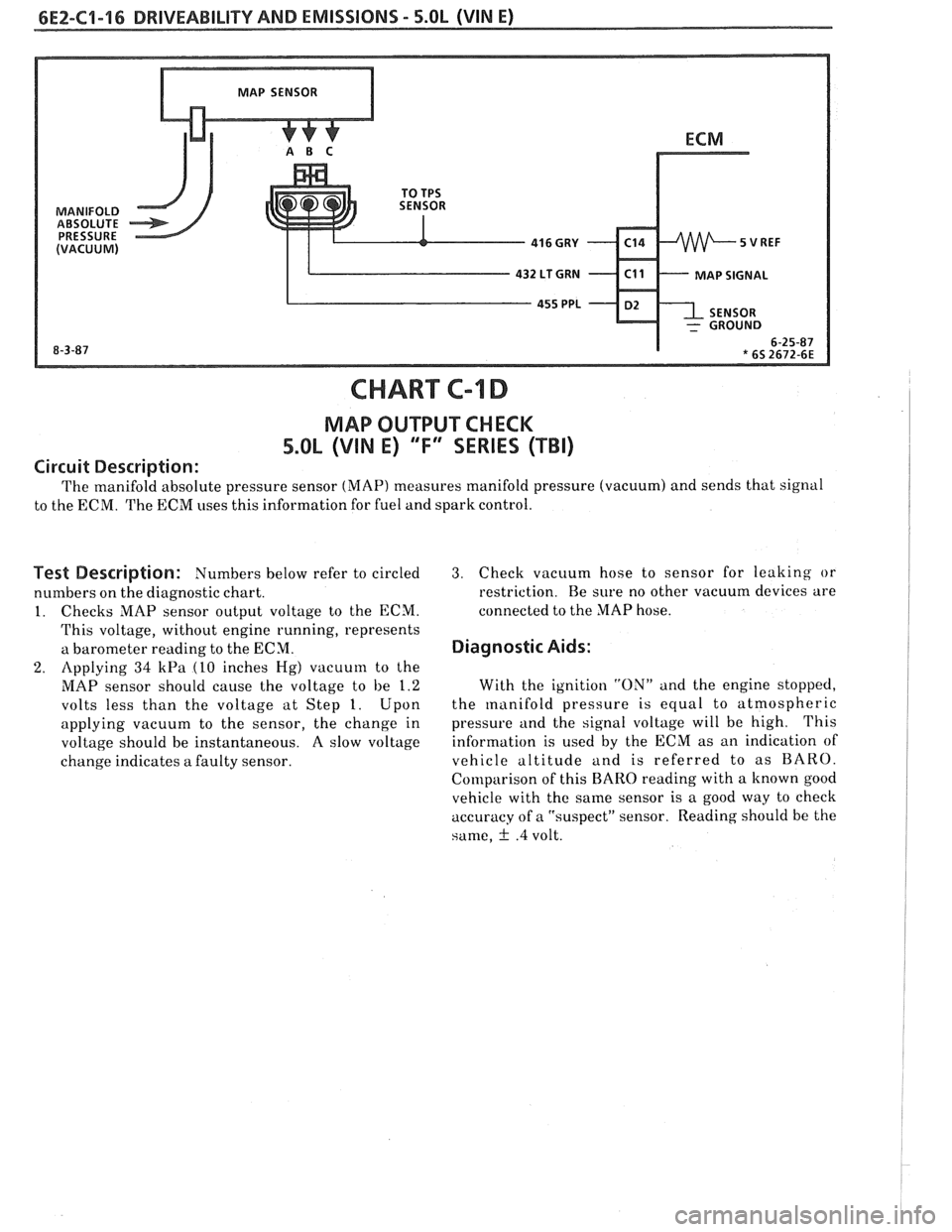
CHART C-l D
MAP OUTPUT CHECK
5.OL (VIN E) 'T" SERIES (TBI)
Circuit Description:
The manifold absolute pressure sensor (MAP) measures manifold pressure (vacuum) and sends that signal
to the ECM. The ECM uses this information for fuel and spark control.
Test Description: Numbers below refer to circled
numbers on the diagnostic chart.
1. Checks MAP sensor output voltage to the ECM.
This voltage, without engine running, represents
a barometer reading to the ECM.
2. Applying 34 kPa (10 inches Hg) vacuum to the
MAP sensor should cause the voltage to be 1.2
volts less than the voltage at Step 1. Upon
applying vacuum to the sensor, the change in
voltage should be instantaneous. A slow voltage
change indicates
a faulty sensor.
3. Check vacuum hose to sensor for leaking or
restriction. Re sure no other vacuum devices are
connected to the MAP hose.
Diagnostic Aids:
With the ignition "ON" and the engine stopped,
the
manifold pressure is equal to atmospheric
pressure and the signal voltage will be high. This
information is used by the ECM as an indication of
vehicle altitude and is referred to as BARO.
Comparison of this
BARO reading with a known good
vehicle with the same sensor is a good way to check
accuracy of a "suspect" sensor. Reading should be the
same,
f .4 volt.
Page 577 of 1825
6EZ-C2-2 DRIVEABILITY AND EMISSIONS - 5.8b (VIN E)
1.5:1 at -36°C (-33°F) to 14.7:1, at 94°C (201°F)
running temperature.
The ECM controls the amount of fuel delivered in
the starting mode by changing how long the injector is
turned "ON" and "OFF". This
is done by "pulsing" the
injector for very short times.
Clear Flood Mode
If the engine floods, clear it by pushing the
accelerator pedal down all the way. The ECM then
pulses the injector at a
20:1 airlfuel ratio, and holds
this injector rate as long as the throttle stays wide
open, and the engine is below 600 rpm. If the throttle
position becomes less than
80%, the ECM returns to
the starting mode.
Run Mode
The run mode has two conditions called "Open
Loop" and "Closed Loop."
Open Loop
When the engine is first started, and it is above
400 rpm, the system goes into "Open Loop" operation.
In "Open Loop," the ECM ignores the signal from the
(02) sensor, and calculates the airlfuel ratio based on
inputs from the coolant temperature and MAP
sensors.
The system stays in "Open Loop" until the
following conditions are met:
1. The
O2 sensor has varying voltage output,
showing that it is hot enough to operate properly.
(This depends on temperature.)
2. The coolant temperature sensor is above a
specified temperature.
3. A specific amount of time has elapsed after
starting the engine.
Closed Loop
The specific values for the above conditions vary
with different engines, and are stored in the
programmable read only memory (PROM). When
these conditions are met, the system goes into "Closed
Loop" operation. In "Closed Loop," the ECM
calculates the
aidfuel ratio (injector on-time) based on
the signal from the
O2 sensor. This allows the aidfuel
ratio to stay very close to 14.7:1.
Acceleration Mode
The ECM looks at rapid changes in throttle
position and manifold pressure, and provides extra
fuel.
Deceleration Mode
When deceleration occurs, the fuel remaining in
the intake manifold can cause excessive emissions and
backfiring. Again, the ECM looks at changes in
throttle position and manifold pressure and reduces
the amount of fuel. When deceleration is very fast, the
ECM can cut off fuel completely for short periods.
Battery Voltage Correction Mode
When battery voltage is low,
the ECM can
compensate for a wealc spark delivered by the
distributor by:
@ Increasing injector on time of fuel delivered;
@ Increasing the idle rpm.
Fuel Cutoff Mode
No fuel is delivered by the injectors when the
ignition is "OFFJ'. This prevents dieseling. Also, fuel
is not delivered if no reference pulses are seen from
the distributor, which means the engine is not
running.
Fuel cutoff also occurs at high engine
rpm, to protect internal engine components from
damage.
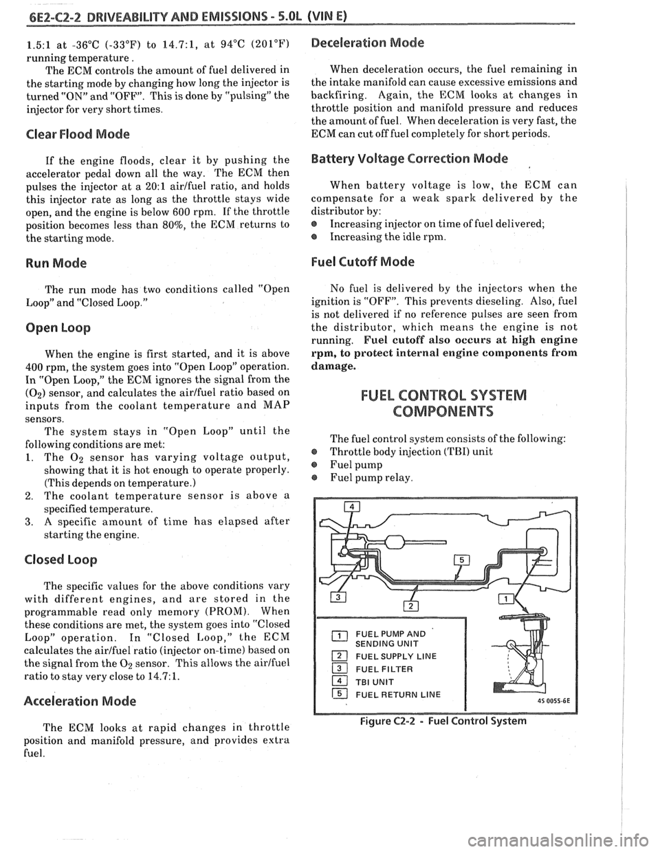
FUEL CON"%ROL SYSXM
COMPONENTS
The fuel control system consists of the following:
@ Throttle body injection (TBI) unit
@ Fuel pump
Fuel pump relay.
FUEL PUMP AND
SENDING UNIT
FUEL SUPPLY LINE
16 FUEL RETURN LINE
Figure C2-2 - Fuel Control System
Page 579 of 1825
6EZ-C2-4 DRIVEABILITY AND EMISSIONS - 5.OL (VIN El
[isj FUEL METER COVER bL BODY ASSEMBLIES
1 THROTTLE BODY ASSEMBLY
1 IDLE AIR CONTROL VALVE ASSEMBLY - FILTERED AIR INLET
PlNTLE
TWRO$TLE VAWE
VACUUM PORTS - FOR ENGINE OR EMISSION
CONTROLS
8P 0319-SY 111 5W7
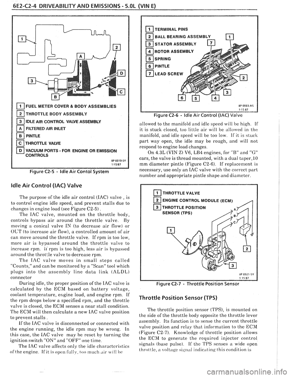
Figure C2-5 - ldle Air Contol System
ldle Air Control (IAC) Valve
The purpose of the idle air control (IAC) valve , is
to control engine idle speed, and prevent stalls due to
changes in engine load (see Figure
C2-5) .
The IAC valve, mounted on the throttle body,
controls bypass air around the throttle valve By
moving a conical valve IN (to decrease air flow) or
OUT (to increase air flow), a controlled amount of air
can move around the throttle valve. If rpm is too low,
more air is bypassed around the throttle valve to
increase rpm.
11 rpnl is too high, less air is bypassed
around the
throt:le valve to decrease rpm.
The IAC valve moves in small steps called
"Counts," and can be monitored by
a "Scan" tool which
plugs into the assembly line data
link (ALDI,)
connector
During idle, the proper position of the IAC valve is
calculated by the ECM based on battery voltage,
coolant temperature,
ellgine load, and engine rpm. If
the rpm drops below a specified rpm, and the throttle
valve is closed, the ECM senses a near stall condition.
The ECM will then calculate a new IAC valve position
to prevent stalls.
If the IAC valve is disconnected or connected with
the engine running, the idle
rpnl may he wrong. In
this case, the
IAC valve may he reset by turning the
ignition switch "ON" and
"OFF" one time
'I'he IAC valve affects only the idle characteristics
of the engine
If it i.; ol)cltl fullv, too much ,LII. tc 111 I)(>
BALL BEARING ASSEMBLY -
STATOR ASSEMBLY
ROTOR
ASSEMBL
I
SPRING
PlNTLE
LEAD SCREW A
Figure C2-6 - ldle Air Control (IAC) Valve
allowed to the manifold and idle speed will he high. if
it is stuck closed, too little air will be
allo\verl in the
manifold, and idle speed will be too low. If it is stuck
part way open, the idle may be rough, and will not
respond to engine load changes.
On
4.3L (VIN Z) V6, LB4 engines, for "B" and "G"
cars, the valve is thread mounted, with a dual taper,lO
mm diameter pintle (Figure C2-6). If replacement is
necessary, use only an IAC valve with the correct part
number and appropriate pintle shape and diameter.
I THROTTLE VALVE
ENGINE CONTROL MODULE (ECM)
,q
THROTTLE POSITION
SENSOR (TPS)
Figure C2-7 - Throttle Position Sensor
Throttle Position Sensor (TPS)
The throttle position sensor ('I'PS), is mounted on
the side of the throttle body opposite the throttle lever
assembly. Its function is to sense the current throttle
valve position
and relkly that information to the ECM
(Figure (22-7). Knowledge of throttle position allows
lhe ECM to generate the recluired i~jector control
signals (base pulse). If the 'I'PS senses a wide open
throttle,
a voltc\ge sic,ll,~I il~tlic~ttinq this condition 13
Page 583 of 1825
6E2-CZ-8 DRIVEABILITY AND EMISSIONS - 5.OL (VIN E)
a FUEL METER COVER A~ACHING SCREW ASSEMBLY - LONG
2 FUEL MmEW COVER AmAC#ING SCREW
ASSEMBLY - SHORT
1 FUEL MmEW COVER GASKET
FUEL METER BODY ASSEMBLY
a THROTTLE BODY /ASSEMBLY
FUEL MnER OUTL- GASKET
PRESSURE
REGUUTOR SUL
FUEL METER COVER ASSEMBLY
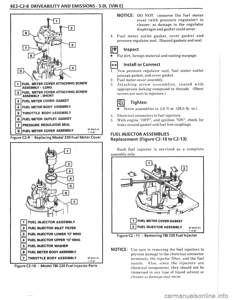
Figure C2-9 - Replacing Model 220 Fuel Meter Cover
FUEL INJECTOR ASSEMBLY
FUEL INJECTOR
lNLm FILTER
FUEL INJECTOR LOWER
"On RlNG
FUEL INJECTOR UPPER "On RlNG
FUEL INJEmR WASHER
NEL METER BODY ASSEMBLY
THROTTLE BODY ASSEMBLY
EP 0925 AS 11587
Figure C2-10 - Model TBI 220 Fuel Injector Parts
NOTSCE: DO NOT immerse the fuel meter
cover (with pressure regulator) in
cleaner, as damage to the regulator
diaphragm and gasket could occur.
4. Fuel meter outlet gasket, cover gasket and
pressure regulator seal. Discard gaskets and seal.
inspect
@ For dirt, foreign material and casting warpage.
Install or Connect
I. New pressure regulator seal, fuel meter outlet
passage gasket, and cover gasket.
'2. Fuel meter cover assembly.
3. Attaching screw assetnblies, coated with
appropriate locking compound to threads. (Short
screws are next to injectors.)
Tighten
e Screw assemblies to 3.0 N.m (28.0 Ib. in.).
4. Electrical connectors to fuel injectors.
5. With engine "OFF", and ignition "ON", check for
leaks around gasket and fuel line couplings.
FUEL INJECTOR ASSEMBLIES
Replacement (Figure CZ-10 to CZ-13)
Each fuel injector is serviced as a complete
assembly only.
FUEL METER COVER GASKET
I Figure C2 - 11 - Removing Ti31 220 Fuel Injector
NOTICE: Use care in removing the Cuel injectors to
prevent
clamage to the electrical connector
terminals, the
in,jector filter, and the fuel
nozzle. Also, since the injectors are
electrical components, they should not be
immersecl in any type of lirluid solvent or
cleaner
as clatnuge may occur.