Page 503 of 1825

6E2-A-12 5.OL (VIN E) DRIVEABILITY AND EMISSIONS
TO OIL PRESS. SW. ECM
&FUEL PUMP RELAY
FUSE
& HOLDER BATTERY 12 V . . . . . . . .
FUSIBLE LINK
439
PNWBLK
419 BRNNVHT
- -
451 WHTIBLK
450
BLWHT
ALDL CONNECTOR
8-4-87
55 1235-6E
CHART A-2
NO ALDL DAM OR WON"T FLASH CODE 12
'SERVICE ENGINE SOON" LLlGHT "ON" "STEADY
5.OL (VIN E) "F" "SERIES (TBI)
Circuit Description:
There should always be a steady "Service Engine Soon" light, when the ignition is "ON" and engine stopped.
Battery is supplied directly to the light bulb. The electronic control module
(ECM) will turn the light "ON" by
grounding CKT 419 at the ECM.
With the diagnostic terminal grounded, the light should flash
a Code 12, followed by any trouble code(s)
stored in memory.
A steady light suggests a short to ground in the light control CKT 419, or an open in diagnostic CKT 451.
Test Description: Numbers below refer to circled
numbers on the diagnostic chart.
1. If there is a problem with the ECM that causes
a
"Scan" tool to not read serial data, then the ECM
should not flash a Code
12. If Code 12 does flash,
be sure that the "Scan" tool is working properly on
another vehicle. If the "Scan" is functioning
properly and CKT 461 is OK, the PROM or ECM
may
be at fault for the NO ALDL symptom.
2. If the light goes "OFF" when the ECM connector is
disconnected, then CKT 419 is not shorted to
ground.
3. This step will check for an open diagnostic CKT
45 1.
4. At this point, the "Service Engine Soon" light
wiring is OK. The problem is a faulty ECM or
PROM. If Code 12 does not flash, the ECM should
be replaced using the original PROM. Replace the
PROM only after trying an ECM, as a defective
PROM is an unlikely cause of the problem.
Page 504 of 1825
DRIVEABILITY AND EMISSIONS 5.OL (VIN E) 6E2-A-13
DISCONNECT ECM CONNECTORS.
CHECK SERIAL DATA CKT461 FOR OPEN OR
IGNITION "ON" AND NOTE
SHORT TO GND. BETWEEN ECM AND ALDL
@ IGNITION "ON", ENGINE STOPPED.
KT 451, WITH TEST
IF OK, REPLACE ECM USING ORIGINAL PROM.
TERMS. "B" AND CKT451 TO ECM.
Page 505 of 1825
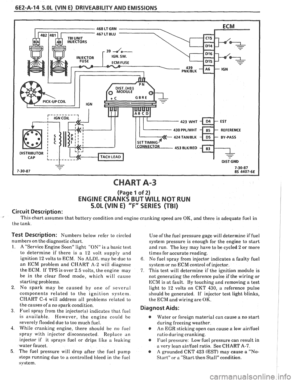
6E2-A-114 5.OL (VIN E) DRIVEABILITY AND EMISSIONS
CHART A-3
(Page I of 2)
ENGINE CRANKS BUT WILL NQ"TRUN
5.OL (VIM E) "F"" SERlES (TBI)
Circuit Description:
This chart assumes that battery condition and engine cranking speed are OK, and there is adequate fuel in
the tank.
Test Description: Numbers below refer to circled
numbers on the diagnostic chart.
1. A "Service Engine Soon" light "ON" is a basic test
to determine if there is a 12 volt supply and
ignition 12 volts to ECM. No
ALIII, may be due to
an ECM problem and CHART A-2 will diagnose
the ECM. If TPS is over 2.5 volts, the engine may
be in the clear flood mode, which will cause
starting problems.
2. No spark may be caused by one of several
components related to the ignition system.
CHART
C-4 will address all problems related to
the causes of a no spark condition.
3. Fuel spray from the injector(s) indicates that fuel
is available. However, the engine could be
severely flooded due to too much fuel.
4. While cranking engine, there should be no
f~lel
spray with injector disconnected. Replace an
injector if it sprays fuel or drips like a leaking
water faucet.
5, The fuel pressure will drop after the fuel pump
stops running due to
a controlled bleed in the fuel
system. Use
of the fuel pressure gage will determine
if fuel
system pressure is enough for the engine to start
and run. The key may have to be cycled
2 or more
times for accurate reading.
6. No fuel spray from injector indicates a faulty fuel
system or no ECM control of injector.
7. This test will determine if the ignition module is
not generating the reference pulse if the wiring or
ECM is at fault. By touching and removing
a test
light to 12 volts on CKT 430,
a reference pulse
should be generated. If
injector test light blinks,
the ECM and wiring are
OK.
Diagnost Aids:
@ Water or foreign material can cause a no start
during freezing weather.
@ An EGR sticking open can cause a low airlfuel
ratio during cranking.
@ Fuel pressure: Low fuel pressure can result in
a very lean airlfuel ratio. See CHART A-7.
@ A grounded CKT 423 (EST) may cause a "No-
Start" or a "Start then Stall" condition.
Page 507 of 1825
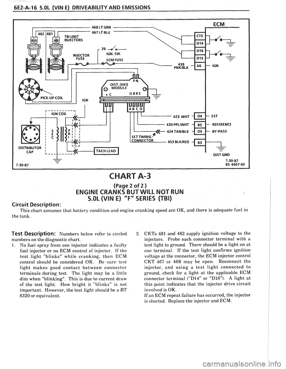
CHART A-3
(Page 2 of 2 )
ENGINE CRANKS BUT WILL NOT RUN
5.OL (VIN E) "F'XSERIES (TBI)
Circuit Description:
This chart assumes that battery condition and engine cranking speed are OK, and there is adequate fuel in
the tank.
Test Description: Numbers below refer to circled 2.
numbers on the diagnostic chart.
1. No fuel spray from one injector indicates a faulty
fuel injector or no ECM control of injector. If the
test light "blinks" while cranking, then
ECM
control should be considered OK. Be sure test
light makes good contact between connector
terminals during test.
The light may be a little
dim when "blinking". This is due to current draw
of the test light. How bright it "blinks" is not
important. However, the test light should be
a BT
8320 or equivalent.
CKTs 481 and 482 supply ignition voltage to the
injectors. Probe each connector terminal with a
test light to ground. There should be a light on at
one terminal.
If the test light confirms ignition
voltage at the connector, the ECM injector control
CKT 467 or 468 may be open. Reconnect the
injector, and using a test light connected to
ground, check for a light at the applicable ECM
connector terminal
("D14" or "D16"). A light at
this point indicates that the injector drive circuit
involved is OK.
If an ECM repeat failure has occurred, the injector
is shorted. Replace the injector and ECM.
Page 509 of 1825
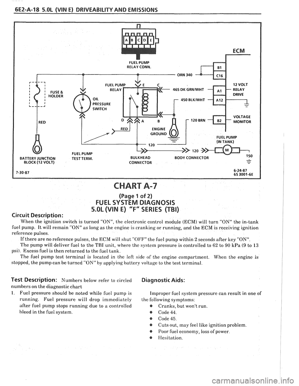
6EZ-Pa-18 5.OL (VIN E) DRIVEABILITY AND EMISSIONS
FUEL PUMP
RELAY CONN.
465 DK GRNMIHT
450 BLWHT
FUEL PUMP
BATTERY JUNCTION TEST TERM. BULKHEAD BODY CONNECTOR
BLOCK
(1 2 VOLT) CONNECTOR
CHART A-7
(Page 1 of 2)
FUEL SYSTEM DlAGNOSlS
5.0L (VIN E) "F"" SERIES (TBI)
Circuit Description:
When the ignition switch is turned "ON", the electronic control module (ECM) will turn "ON" the in-tank
fuel pump. It will remain "ON"
as long as the engine is cranking or running, and the ECM is receiving ignition
reference pulses.
If there are no reference pulses, the ECM will shut
"OI'F" the fuel pump within 2 seconds after key "ON".
The pump will deliver fuel to the THI unit, where the system pressure is controlled to 62 to 90 kPa (9 to 13
psi). Excess fuel is then returned to the fuel tank.
The fuel pump test terminal is located in the left side of the engine compartment. When the engine is
stopped, the pump can be turned "ON" by applying battery voltage to the test terminal.
lest Description: Numbers below refer to circled Diagnostic Aids:
numbers on the diagnostic chart
1. Fuel pressure should be noted while fuel pump is Improper fuel system pressure can result in one of
running. Fuel pressure will drop immediately the following symptoms:
after fuel pump stops running due to a controlled
e Cranks, but won't run.
bleed in the fuel system.
@ Code 44.
@ Code 45.
@ Cuts out, may feel like ignition problem.
@ Poor fuel economy, loss of power.
FIesitation.
Page 519 of 1825
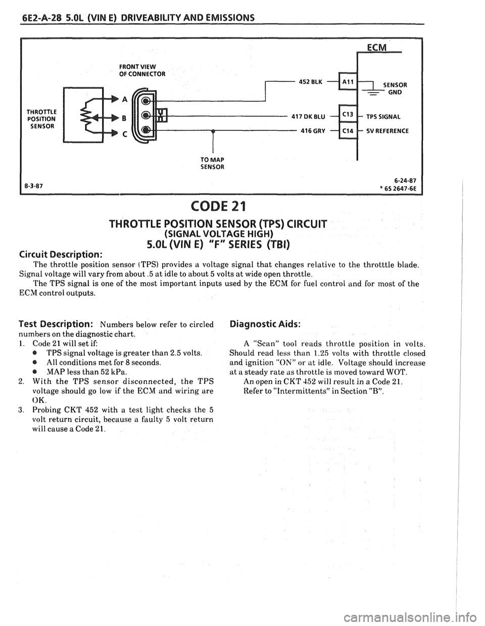
6EZ-A-28 5.OL (VIN E) DRIVEABILITY AND EMISSIONS
FRONT VIEW OF CONNECTOR
5V REFERENCE
TO
MAP SENSOR
CODE 21
THROTLE POSITION SENSOR (TPS) CIRCUIT
(SIGNAL VOLTAGE HIGH)
5.OL (VIN E) "F" "SERIES ("FBI)
Circuit Description:
The throttle position sensor (TPS) provides a voltage signal that changes relative to the throtttle blade.
Signal voltage will vary from about
.5 at idle to about 5 volts at wide open throttle.
The TPS signal is one of the most important inputs used by the ECM for fuel control and for most of the
ECM control outputs.
Test Description: Numbers below refer to circled
numbers on the diagnostic chart.
1. Code
21 will set if:
@ TPS signal voltage is greater than 2.5 volts.
@ All conditions met for 8 seconds.
@ MAP less than 52 kPa.
2. With the TPS sensor disconnected, the TPS
voltage should go low if the ECM and wiring are
OK.
3. Probing CKT 452 with a test light checks the 5
volt return circuit, because a faulty 5 volt return
will cause
a Code 21.
Diagnostic Aids:
A ''Scan" tool reads throttle position in volts.
Should read less than 1.26 volts with throttle closed
and ignition
"Oili" or at idle. Voltage should increase
at a steady rate as throttle is moved toward
WOT.
An open in CKT 152 will result in a Code 21.
Refer to
"Intermittents" in Section "B".
Page 521 of 1825
FRONT VIEW OF CONNECTOR
5V REFERENCE
SENSOR
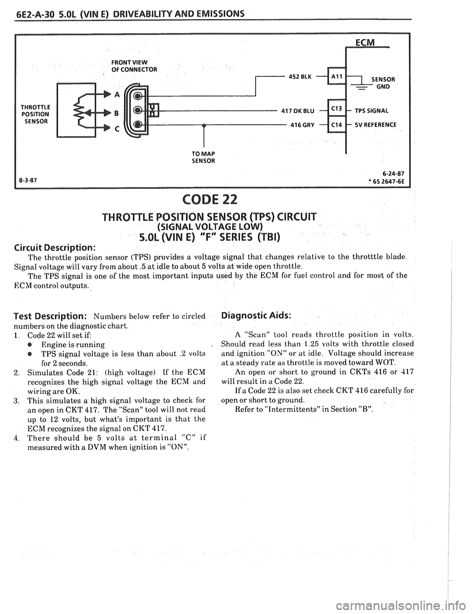
CODE 22
THROTTLE POSITION SENSOR (TPS) CIRCUIT
(SIGNAL VOLTAGE LOW)
5.OL (VIN E) "'F3ERIES (TBI)
Circuit Description:
The throttle position sensor (TPS) provides a voltage signal that changes relative to the throtttle blade.
Signal voltage will vary from about
.5 at idle to about 5 volts at wide open throttle.
The TPS signal is one of the most important inputs used
by the ECM for fuel control and for most of the
ECM control outputs.
Test Description: Numbers below refer to circled
numbers on the diagnostic chart.
1. Code 22 will set if:
Engine is running
r TPS signal voltage is less than about .2 volts
for
2 seconds.
2. Simulates Code 21: (high voltage) If the ECM
recognizes the high signal voltage the ECM and
wiring are OK.
3. This simulates a high signal voltage to check for
an open in CKT 417. The "Scan" tool will not read
up to 12 volts, but what's important is that the
ECM recognizes the signal on CKT 417.
4. There should be
5 volts at terminal "C" if
measured with a DVM when ignition is "ON".
Diagnostic Aids:
A "Scan" tool reads throttle position in volts.
Should read less than 1.25 volts with throttle closed
and ignition "ON" or at idle. Voltage should increase
at a steady rate as throttle is moved toward WOT.
An open
or short to ground in CKTs 416 or 417
will result in a Code 22.
If a Code 22 is also set check CKT 416 carefully for
open or short to ground.
Refer to "Intermittents" in Section
"B".
Page 526 of 1825
DRIVEABILITY AND EMISSIONS 5.OL (WIN E) 6E2-A-35
NOTE: TO PREVENT MISDIAGNOSIS, THE TECHNICIAN SHOULD REVIEW ELECTRICAL SECTION "8A"
OR THE ELECTRICAL TROUBLESHOOTING MANUAL AND IDENTIFY THE TYPE OF VEHICLE
SPEED SENSOR USED PRIOR TO USING THIS CHART. DISREGARD CODE
24 IF SET WHEN
DRIVE WHEELS ARE NOT TURNING.
CTOR TERMINAL "K"
e IGNITION "ON." @ BACK PROBE 15-WAY I.P. CONNECTOR
ISPLAY 10 VOLTS OR MORE.
ONNECTOR AND
VSS BUFFER
CLEAR CODES AND CONFIRM "CLOSED LOOP
" OPERATION AND NO "SERVICE ENGINE SOON" LIGHT.