1988 PONTIAC FIERO ignition
[x] Cancel search: ignitionPage 394 of 1825
V-8 ENGINE 6A3-15
engine to deliver the power and performance built into
it.
Another important factor is the cooling of the
valve heads. Good contact between each valve and its
seat in the head is imperative to insure that the heat in
the valve head will be properly carried away.
Several different types of equipment are available
for reseating valves seats. The recommendations of the
manufacturer of the equipment being used should be
carefully followed to attain proper results.
Regardless of what type of equipment is used,
however, it is essential that valve guide bores be free
from carbon or dirt to ensure proper centering of pilot
in the guide. Valve seats should be concentric to within
,002" total indicator reading.
VALVES
Valves that are pitted can be refaced to the proper
angle, insuring correct relation between the head and
stem on a valve
refacing mechanism. Valve stems
which show excessive wear, or valves that are warped
excessively should be replaced. When a valve head
which is warped excessively is
refaced, a knife edge will
be ground on part or all of the valve head due to the
amount of metal that must be removed to completely
reface. Knife edges lead to breakage, burning or
pre-ignition due to heat localizing on this knife edge.
If the edge of the valve head is less than 1/32"
(.08mm)
thick after grinding, replace the valve. Several different
types of equipment are available for
refacing valves.
The recommendation of the manufacturer of the
equipment being used should be carefully followed to
attain proper results.
TORSIONAL DAMPER
Removal
1.
Remove drive belts and pulley.
2. Raise vehicle.
3. Remove crankshaft pulley, then remove damper
retaining bolt.
4. Install Tool J-23523 on damper then, turning
puller screw, remove damper.
Installation
NOTICE: The inertial weight section of the
torsional damper is assembled to the hub with a
rubber type material. The installation procedures
(with proper tool) must be followed or movement
of the inertia weight section on the hub will
destroy the tuning of the torsional damper.
1. Inspect the cover seal contact area surface (on
damper) for damage or grooving and coat front
cover seal with engine oil.
2. Place damper in position over key on crankshaft.
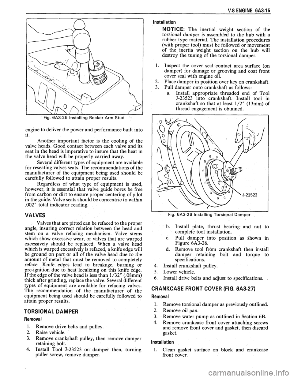
3. Pull damper onto crankshaft as follows:
a. Install appropriate threaded end of Tool
J-23523 into crankshaft. Install tool in
crankshaft so that at least
1/2" (13mm) of
thread engagement is obtained.
Fig. 6A3-26 Installing Torsional Damper
b.
Install plate, thrust bearing and nut to
complete tool installation.
c. Pull damper into position as shown in
Figure 6A3-26.
d. Remove tool from crankshaft then install
damper retaining bolt and torque to
specifications.
4. Install crankshaft pulley.
5. Lower vehicle.
6. Install drive belts and adjust to specifications.
CRANKCASE FRONT COVER (FIG. 6A3-27)
Removal
1.
Remove torsional damper as previously outlined.
2. Remove oil pan.
3. Remove water pump as outlined in Section
6B.
4. Remove crankcase front cover attaching screws
and remove front cover and gasket, then discard
gasket.
lnstallation
1. Clean gasket surface on block and crankcase
front cover.
Page 417 of 1825
6B-8 ENGINE COOLING
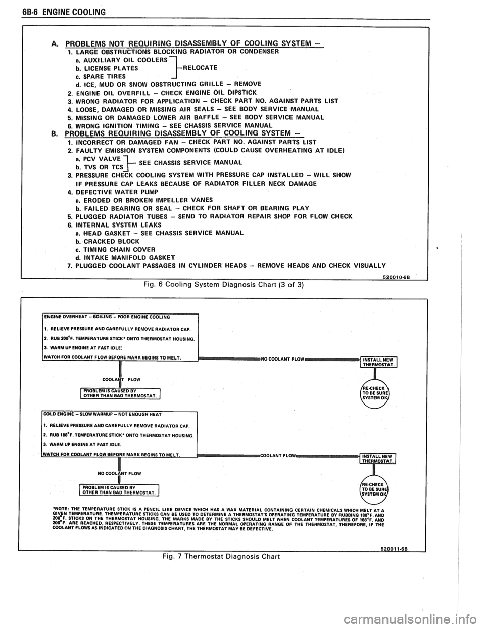
PROBLEMS NOT REQUIRING DISASSEMBLY OF COOLING SYSTEM - 1. LARGE OBSTRUCTIONS BLOCKING RADIATOR OR CONDENSER
a. AUXILIARY OIL COOLERS
b. LICENSE PLATES R ELOCATE
c. SPARE TIRES
d. ICE, MUD OR SNOW OBSTRUCTING GRILLE - REMOVE
2. ENGINE OIL OVERFILL - CHECK ENGINE OIL DIPSTICK
3. WRONG RADIATOR FOR
APPLICATION - CHECK PART NO. AGAINST PARTS LlST
4. LOOSE, DAMAGED OR MISSING AIR SEALS - SEE BODY SERVICE MANUAL
5. MISSING OR DAMAGED LOWER AIR BAFFLE - SEE BODY SERVICE MANUAL
6. WRONG IGNITION TIMING - SEE CHASSIS SERVICE MANUAL PROBLEMS REQUIRING DISASSEMBLY OF COOLING SYSTEM -
1. INCORRECT OR DAMAGED FAN - CHECK PART NO. AGAINST PARTS LlST
2. FAULTY EMISSION SYSTEM COMPONENTS (COULD CAUSE OVERHEATING AT IDLE)
; SEE CHASSIS SERVICE MANUAL
3. PRESSURE CHECK COOLING SYSTEM WITH PRESSURE CAP INSTALLED - WILL SHOW
IF PRESSURE CAP LEAKS BECAUSE OF RADIATOR FILLER NECK DAMAGE
4. DEFECTIVE WATER PUMP
a. ERODED OR BROKEN IMPELLER VANES
b. FAILED BEARING OR SEAL - CHECK FOR SHAFT OR BEARING PLAY
5. PLUGGED RADIATOR TUBES - SEND TO RADIATOR REPAIR SHOP FOR FLOW CHECK
6. INTERNAL SYSTEM LEAKS
B. HEAD GASKET - SEE CHASSIS SERVICE MANUAL
b. CRACKED BLOCK
c. TIMING CHAIN COVER
d. INTAKE MANIFOLD GASKET
7. PLUGGED COOLANT PASSAGES IN CYLINDER HEADS - REMOVE HEADS AND CHECK VISUALLY
Fig. 6 Cooling System Diagnosis Chart (3 of 3)
1. RELIEVE PRESSURE AND CAREFULLY REMOVE RADIATOR CAP.
2. RUB W'F. TEMPERATURE STICK* ONTO THERMOSTAT MOUSING.
3. WARM UP ENGINE AT FAST IDLE:
WATCH FOR COOLANT FLOW BEFORE MAR
NO COOLANT FLOW INSTALL NEW
THERMOSTAT.
COLD ENGINE -SLOW WARMUP -NOT ENOUGH HEAT
1. RELIEVE PRESSURE AND CAREFULLY REMOVE RADIATOR CAP.
2. RUB 188'~. TEMPERATURE STICK' ONTO THERMOSTAT HOUSING.
3. WARM UP ENGINE AT FAST IDLE.
COOLANT FLOW
- 'NOTE: THE TEMPERATURE STICK IS A PENCIL LIKE DEVICE WHICH HAS A WAX MATERIAL CONTAINING CERTAIN CHEMICALS WHICH MELT AT A GIVEN TEMPERATURE THEWERATURE STICKS CAN BE USED TO DETERMINE A THERMOSTAT'S OPERATING TEMPERATURE BY RUBBING laB°F AN0 =OF. STICKS ON THE THERMOSTAT HOUSING. THE MARKS MADE BY THE STICKS SHOULD MELT WHEN COOLANT TEMPERATURES OF IWOF'AND W'F. ARE REACHED, RESPECTIVELY. THESE TEMPERATURES ARE THE NORMAL WERATING RANGE OF THE THERMOSTAT. THEREFORE, ~i WE COOLANT FLOWS AS INDICATED ON THE DIAGNOSIS CHART. THE THERMOSTAT MAY BE DEFECTIVE.
Fig. 7 Thermostat Diagnosis Chart
Page 426 of 1825

ENGINE COOLING 6B-15
1. 27 N-m (20 LBS. FT.)
2. 34 N.m (25 LBS. FT.)
Fig. 602 Thermostat - V.I.N. E, F and 8
ELECTRIC COOLING FAN
CAUTION: Keep hands, tools, and
clothing away from engine cooling fan
to help prevent personal injury. This
fan is electric and can come on
whether or not the engine is running.
The fan can start automatically in
response to a heat sensor with the
ignition in the "On" position.
Remove or Disconnect
1. Negative battery cable.
2. Harness from fan motor and fan frame.
3. Fan
frame to radiator support attaching bolts.
4. Fan and frame assembly.
Install or Connect
1. Fan and frame assembly.
2. Fan frame to radiator support attaching bolts and
torque to specification.
3. Harness
to fan frame and fan motor.
4. Negative battery cable.
Inspect
For proper completion of repairs.
For operation of fan motor.
WATER PUMP
Remove or Disconnect
1. Battery negative cable at battery.
2. Cooling system.
3. If equipped with M.F.I., remove air intake tube
and mass air flow sensor.
4. Fan and radiator upper support, as applicable.
5. Serpentine belt.
6. Generator upper and lower brackets, A/C brace
and bracket and, if equipped, power steering
pump lower bracket from water pump and swing
aside.
7. Radiator lower hose and heater hose from water
Pump.
8. Water pump to block attaching bolts and remove
water pump.
Install or Connect
s If installing a new water pump, transfer
heater hose fitting from old unit.
With clean sealing surfaces on both block and water
pump, install water pump to block with new gaskets
and retain with attaching bolts. Torque to specifica-
tions. (V6 small bolt
10N.m, 7 lb. ft., large bolt and
nut 20
N-m, 15 lb. ft.) (V8-40 Nsm, 30 lb. ft.)
Radiator lower hose and heater hose to water pump
and torque clamps to 2
N.m (20 lb. in.).
Generator upper and lower brackets and, if
equipped, the power steering pump lower bracket to
the water pump. Torque bolts to 41
N.m (30 lb. in.).
Serpentine belt.
If equipped with M.F.I., install air intake tube
and mass air flow sensor.
Fan and radiator upper support, as applicable.
Battery negative cable.
Fill cooling system with an ethylene glycol
antifreeze and water mixture of
50/50.
Start engine and run, with radiator cap removed,
until radiator upper hose becomes hot
(thermostat open).
With engine idling, add coolant to radiator until
level reaches bottom of filler neck.
Cap, making sure arrows line up with overflow
tube.
Fig. 603 Fan Mounting V.I.N. E, S (All) F, 8 (wlo A/C)
Page 434 of 1825
ENGINE FUEL 6C.3
a Fuel feed and return pipes are secured to the
underbody with clamps and screw assemblies.
The pipes should be inspected occasionally for
leaks, kinks or dents.
e Follow the same routing as the original pipe.
e Pipes must be properly secured to the frame to
prevent chafing. A minimum of 6 mm
(1/4")
clearance must be maintained around a pipe to
prevent contact and chafing.
MPFl Fuel Pipes
Due to the fact that fuel pipes are under high
pressure, these systems require special consideration for service.
Many feed and return pipes use screw couplings
with
"0" Rings. Any time these fittings are loosened
to service or replace components, ensure that:
a A backup wrench is used while loosening and
tightening the fitting.
e Check all "0" rings at fitting locations (if
applicable) for cuts or any damage and replace
any that appear worn or damaged.
e Use correct torque when tightening fittings.
If pipes are replaced always use original
equipment parts, or parts that meet GM
specifications.
Fuel and Vapor Hoses
NOTICE: Fuel and vapor hoses are specially
manufactured. If replacement becomes necessary,
it is important to use only replacement hoses
meeting GM Specification 6163-M. These hoses
are identified with the words "Fluoroelastomer"
on them. Hoses not so marked could cause early
failure, or fail to meet emission standards.
e Do not use rubber hose within 4" of any part of
the exhaust system, or within
10" of the catalytic
converter.
FUEL PUMP
The electric fuel pump is in the fuel tank. The
tank has an outlet for a vapor return system. Any vapor
which forms is returned to the fuel tank along with hot
fuel through a separate line. This greatly reduces any
possibility of vapor lock by keeping cool fuel from the
tank constantly circulating through the fuel pump.
FUEL PUMP RELAY
To control fuel pump operation, a fuel pump
relay is used.
When the ignition switch is turned to "RUN"
position, the fuel pump relay activates the electric fuel
pump for
1.5 to 2.0 seconds to prime the injector(s). If
the ECM does not receive reference pulses from the
distributor after this time, the ECM signals the relay
to turn off the fuel pump. The relay will once again
activate the fuel pump when the
ECM receives
distributor reference pulses.
Fuel Filter
CAUTION: To reduce the risk of fire
and personal injury, it is necessary
to
relieve the fuel system pressure
before servicing fuel system
components. (See Fuel System
Pressure Relief.)
The inline filters can be found on the rear
crossmember of the vehicle. Always use a backup
wrench any time that the fuel filter is removed or
installed. Also make sure that a good
"0" Ring is used
at all screw couple locations. Torque on fittings is
30
N-m (22 lb. ft.).
FUEL TANK
The fuel tank is usually located under the rear of
the vehicle and a number of shapes and sizes are used
depending on the application.
The tank is held in place by two metal straps,
hinged (with a bolt through the hinge) and secured at
the opposite end with a nut and bolt assembly.
Anti-squeak pieces are used on top of the tank to
reduce rattles and other annoying noises.
The fuel tank, cap and lines should be inspected
for road damage, whch could cause leakage. Inspect
fuel cap for correct sealing and indications of physical
damage. Replace any damaged or malfunctioning
parts.
Before attempting service of any type on the fuel
tank, always
(1) remove negative battery cable from
battery, (2) place "no smoking" signs near work areas,
(3) be sure to have C02 fire extinguisher handy, (4)
wear safety glasses and
(5) siphon or pump fuel into an
explosion proof container.
Fuel Filler Gap
The fuel tank filler neck is equipped with a
screw-type cap. The threaded part of the cap requires
several turns counterclockwise to remove. The long
threaded area is designed to allow any remaining fuel
tank pressure to escape while the cap is being removed.
A built-in torque-limiting device prevents
overtightening. To install, turn the cap clockwise until
a clicking noise is heard. This signals that the correct
torque has been reached and the cap is fully seated.
N OTI G E: If a fuel filler cap requires replacement,
use only a cap with the same features. Failure to
use the correct cap can result in a serious
malfunction of the system.
Available on some models is an electric locking
fuel filler cap. Information on this option will be found
in Section
9E.
FUEL TANK FILLER NECK
To help prevent refueling with leaded gasoline,
the fuel filler neck on gasoline engine cars has a built-in
restrictor and deflector. The opening in the restrictor
will only admit the smaller unleaded gas nozzle spout,
which must be fully inserted to bypass the deflector.
Attempted refueling with a leaded gas nozzle or failure
Page 435 of 1825

6C-4 ENGINE FUEL
to fully insert the unleaded gas nozzle will result in
gasoline splashing back out of the filler neck.
Fuel Gage Sending Unit
The fuel gage sending unit is attached to the top
of the fuel tank. It is held in place with a cam lock ring
and a gasket is used between the tank and sending unit.
Sending units have three hoses attached. One line
is for the fuel feed. The second line is connected to the
vapor canister, to keep fuel vapor from getting into the
air (see Section 6E). The third line is used as a fuel
return line to the tank.
On some sending units a wire is attached to the
unit. On others the connectors attach directly to the
sender.
When a fuel gage sending unit is removed always
make sure to install the gasket and any power or
ground leads that were removed.
DIAGNOSIS
Fuel system diagnostic procedures are located in
Section(s) 6E1 thru 6E3.
SERVICE PROCEDURES
If the fuel system is suspected of delivering an
improper amount of fuel, it should be inspected and
tested in the vehicle, as follows:
1. Make certain that there is fuel in the tank.
2. With the engine running, inspect for leaks at all
fuel feed pipe and hose connections from
fuel
tank to injection pump. Tighten any loose
connections. Inspect all hoses for flattening or
kinks which would restrict the flow of fuel. Air
leaks or restrictions on suction side of fuel pump
will seriously affect pump output.
FUEL SYSTEM PRESSURE RELIEF
CAUTION: To reduce risk of fire and
personal injury, it is necessary to
relieve duel system pressure before
servicing fuel system components. To
do this:
Remove "fuel pump" fuse from fuse
block in passenger compartment.
e Crank engine - engine will start and run
until fuel supply remaining in fuel lines is
consumed. Engage starter for
3.0
seconds to assure relief of any remaining
pressure.
e With ignition "OFF", replace duel pump
fuse.
Unless this procedure
is followed before
servicing fuel lines
or connections, fuel
spray could occur.
When repair to the fuel system has been
completed, start engine and check all connections that
were loosened for possible leaks.
Refer to Section 6E for additional diagnosis of
engine fuel system.
Fuel Pump Flow Test
1. Test fuel
pump by connecting hose from EFI fuel
feed line to a suitable unbreakable container.
Apply battery voltage to the fuel pump test
terminal (terminal
"G" of ALCL).
2. Fuel pump should supply
1/2 pint or more in 15
seconds.
3. If flow is below minimum, check for fuel
restriction. If there is no restriction, check pump
pressure.
Fuel System Pressure Test
This test must be performed when diagnosing the
fuel system.
CAUTION: To reduce the risk of fire
and personal injury, it is necessary to
relieve fuel system pressure before
servicing fuel system components on
the
TBI system. To do this:
s Remove "Fuel Pump" fuse from fuse block in
passenger compartment.
e Crank engine. Engine will start and run until fuel
remaining in fuel lines is consumed. Crank the
starter for three seconds to assure that any
remaining pressure is relieved.
e With the ignition off, replace the "Fuel Pump"
fuse.
1. Obtain two
sections of
3/8" steel tubing. Each
should be about 254 mm (10 inches) long.
I
Double-flare one end of each section.
2. Install a flare nut on each section. Connect each i
of the above sections of tubing into the "flare nut 1
to flare nut adapters" that are included in J-29658 i
Gage Adapters.
3. Attach the
pipe and adapter assemblies to the
J-29658 gage.
4. Hoist the car.
5. Disconnect
front fuel feed hose from the fuel pipe
on the body.
1
6. Install a
254 mm (10 inch) length of 3/8" fuel
hose onto the fuel feed pipe on the body. Attach 1
I the other end of the hose onto one of the sections
of pipe mentioned in Step 1. Secure the hose
connections with clamps.
7. Attach the front fuel feed hose onto the other
i
section of tubing mentioned in Step 1. Secure the I
hose connection with a clamp. I
8. Start
the engine and check for leaks. I 9. Observe
the fuel pressure reading. It should be 62
to 90
kPa (9 to 13 psi). If not, refer to the I
appropriate Emissions Section.
10. Depressurize
the fuel system and remove the gage I
with adapters. Reconnect the fuel feed hose to the
pipe and torque the clamp to
1.7 N.m (1 5 lb. in.).
11. Lower
the car. Start the engine and check for fuel
leaks.
Fuel System Pressure Test- MPFl
Fuel system diagnosis is in Section 6E3, Chart
A-7.
Page 436 of 1825
ENGINE FUEL CC-5
FUEL TANK
Draining Fuel Tank
1. Disconnect the negative battery cable. Also have
a dry chemical (Class B) fire extinguisher near the
work area.
2. Use a hand operated pump device when possible
to drain as much fuel through the filler tube as
possible.
3. If
a hand operated pump device cannot be used
to complete the draining process, use a siphon at
the main (not return) fuel pipe at the fuel pump
or the fuel tank gage unit.
CAUTION: Never drain or store
gasoline in an open container due to
the possibility of fire or explosion.
4. Reinstall any removed hoses, lines and cap.
Removing Fuel Tank
1. Remove all fuel, see "Draining Fuel Tank".
2. Support
fuel tank and disconnect the two fuel
tank retaining straps.
3. Lower tank enough to disconnect sending unit
wire, hoses, and ground strap, if so equipped.
4. Remove tank from vehicle.
5. Remove sending unit.
Installing Fuel Tank
1. Reverse removal procedure.
2. Always replace "0" ring when tank unit has been
removed.
3. When reinstalling fuel tank, be sure to reinstall
anti-squeak pieces on top of the tank to reduce
rattles and other annoying noises.
4. Tighten fuel tank retaining strap bolts or screws.
Fuel System Cleaning
CAUTION: This procedure will NOT
remove all fuel vapor. Do not attempt
any repair
on tank or filler neck where
heat or flame is required, as an
explosion resulting in personal injury
could occur.
If trouble is due to contaminated fuel or foreign
material that is in the tank, it can usually be cleaned.
If tank is rusted internally, it should be replaced.
1. Disconnect negative battery cable.
2. Disconnect ignition engine harness connector.
Have dry chemical (Class B) fire extinguisher
near the work area.
3. Relieve fuel system pressure.
4. Drain fuel tank (see "Draining Fuel Tank").
5. Remove fuel tank (see "Fuel Tank Removal").
6. Remove external fuel filter and inspect for
contamination. If filter is plugged, replace.
7. Locate tank away from heat, flame, or other
source of ignition. Remove fuel gage sending unit
and fuel pump assembly, if so equipped, and
inspect condition of strainer. If strainer is
contaminated, a new strainer should be installed.
8. Complete draining of tank by rocking it and
allowing fuel to run out of fuel sending unit
opening.
9. Flush fuel tank with running hot water for at least
five minutes. Pour water out of fuel sending unit
opening. (Rock tank to be sure that removal of
water is complete.)
10. Disconnect fuel feed pipe and use air pressure to
clean fuel line. Apply air pressure in the opposite
direction fuel normally flows through the line. On
vehicles equipped with a fuel return line, clean
line in similar manner. Disconnect pipe at
throttle body unit and apply air pressure to clean
return line. Reconnect and torque all pipes to 30
N-m (22 1b. ft.).
11. Use low air pressure to clean pipes on fuel gage
sending unit.
112. Install new strainer on fuel gage sending unit, if
required. Install fuel gage sending unit and fuel
pump, with new gasket, into tank and install fuel
tank. Connect fuel gage wire harness to body
harness. Connect all fuel lines except feed line to
external fuel filter.
13. Disconnect fuel feed hose to chassis pipe at front.
Connect a hose to front end of chassis fuel feed
pipe and insert other end of hose into a one gallon
fuel can.
14. Connect battery cable.
15. Put six gallons of clean fuel into fuel tank and
apply 12 volts to Terminal
"G" of ALCL to
operate fuel pump. Pump two quarts of fuel into
fuel can. This will purge fuel pump.
16. Remove hose and connect fuel hose to chassis
pipe.
17. Check all connections
for leaks; tighten all hose
clamps.
Fuel Tank Purging Procedure
The following procedure is used prior to repairing
of fuel tank.
1. Remove fuel sending unit and fuel pump and
drain all remaining fuel from tank.
2. Visually inspect interior cavity of tank. If any fuel
is evident, drain again.
3. Move tank to flushing area (wash rack).
4. Fill tank completely with tap water, agitate
vigorously and drain.
5. Add gasoline emulsifying agent to the tank, refill
with water, agitate mixture for 10 minutes, and
drain tank completely.
For correct gasoline emulsifying agent-to-water
mixture, refer to the
manufacturer's
specifications. Use an available emulsifying
agent, such as "Product-Sol No.
913", or
equivalent.
6. When empty, refill the tank to overflowing with
water. Completely flush out remaining mixture
and empty tank.
7. If available, an explosion meter should be used Lo
check for negative reading.
8. Perform required service work.
Page 444 of 1825
BATTERY 6D1.1
SECTION 6Dl
BATTERY
CONTENTS
.......................... .. General Description ................................ 6D1- 1 Battery Charging ...... 6D 1-2
Battery .......................... ... ....................... 6D 1 - 1 Charging Completely Discharged
.................................................... ............................. Ratings .................... ... 6D 1 - 1 Battery 6D 1-3
........................................... Reserve Capacity ..................................... 6D 1 - 1 Jump Starting 6D
1-4
Cranking ............a*............ 6D1-1 On-Gar Service ...................................... 6Dl-5 .................................. Built-In Hydrometer 6D 1-2 Battery Cable Routing ............................... 6D 1-5 Diagnosis ................................................... 6Dl-2
Specifications .............................................. 6D 1-7 ............................. Service Procedures ..... 6D 1-2
GENERAL DESCRIPTION
The engine electrical system includes the battery,
ignition (primary and secondary), starter (and related
wiring) and the generator (and related wiring).
Diagnostic charts (see Section 6D) will aid in
trouble-shooting system faults. When a fault is traced
to a particular component, refer to that components'
section of the service manual.
BATTERY
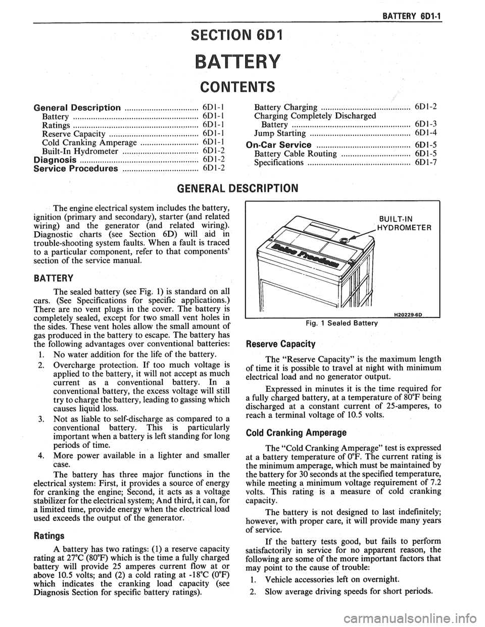
The sealed battery (see Fig. 1) is standard on all
cars. (See Specifications for specific applications.)
There are no vent plugs in the cover. The battery is
completely sealed, except for two small vent holes in
the sides. These vent holes allow the small amount of
gas produced in the battery to escape. The battery has
the following advantages over conventional batteries:
1. No water addition for the life of the battery.
2. Overcharge protection. If too much voltage is
applied to the battery, it will not accept as much
current as a conventional battery. In a
conventional battery, the excess voltage will still
try to charge the battery, leading to gassing which
causes liquid loss.
3. Not as liable to self-discharge as compared to a
conventional battery. This is particularly
important when a battery is left standing for long
periods of time.
4. More power available in a lighter and smaller
case.
The battery has three major functions in the
electrical system: First, it provides a source of energy
for cranking the engine; Second, it acts as a voltage
stabilizer for the electrical system; And third, it can, for
a limited time, provide energy when the electrical load
used exceeds the output of the generator.
Ratings
A battery has two ratings: (1) a reserve capacity
rating at 27°C (80°F) which is the time a fully charged
battery will provide 25 amperes current flow at or
above 10.5 volts; and (2) a cold rating at -18°C (0°F)
which indicates the cranking load capacity (see
Diagnosis Section for specific battery ratings).
BUILT-IN
HYDROMETER
Fig. 1 Sealed Battery
Reserve Capacity
The "Reserve Capacity" is the maximum length
of time it is possible to travel at night with minimum
electrical load and no generator output.
Expressed in minutes it is the time required for
a fully charged battery, at a temperature of 80°F being
discharged at a constant current of 25-amperes, to
reach a terminal voltage of 10.5 volts.
Cold Cranking Amperage
The "Cold Cranking Amperage" test is expressed
at a battery temperature of
0°F. The current rating is
the minimum amperage, which must be maintained by
the battery for 30 seconds at the specified temperature,
while meeting a minimum voltage requirement of 7.2
volts. This rating is a measure of cold cranking
capacity.
The battery is not designed to last indefinitely;
however, with proper care, it will provide many years
of service.
If the battery tests good, but fails to perform
satisfactorily in service for no apparent reason, the
following are some of the more important factors that
may point to the cause of trouble:
1. Vehicle
accessories left on overnight.
2. Slow
average driving speeds for short periods.
Page 447 of 1825
6D1-4 BATTERY
VOLTAGE
A. 16.0 or more
B. 14.0
- 15.9
C. 13.9 or less HOURS
1. Set parking brake and place automatic
Up to 4 Hours transmission in "PARK" (NEUTRAL for
Up to 8 Hours manual transmission.) Turn off the ignition,
Up to 16 Hours turn off lights, and all other electrical
If the charge current is still not
measurable
at the end of the above charging
times, the battery should be replaced.
If the charge current is measurable during
the charging time, the battery is considered to be
good and charging should be completed in the
normal manner.
5. It
is important to remember that a completely
discharged battery must be recharged for a
sufficient number of ampere hours (AH) to
restore it to a usable state. As a general rule of
thumb, using the reserve capacity rating (RC) of
the battery as the number of ampere hours of
charge will usually bring the green dot into view.
For example, if battery is rated at 75 RC minutes,
it would be completely recharged as follows:
10 ampere charge x 7-1/2 hours
= 75 AH
25 ampere charge x 3 hours = 75 AH, etc.
6. It
is recommended that any battery recharged by
this procedure be
LOAD TESTED to establish
serviceability.
JUMP STARTING IN CASE OF EMERGENCY
WITH AUXILIARY (BOOSTER) BAVEEWY
NOTICE: Do not push or tow the vehicle to start.
Damage to the emission system, or to other parts
of the vehicle may result.
Both booster and discharged battery should be
treated carefully when using jumper cables. Follow the
procedure outlined below, being careful not to cause
sparks:
CAUTION: Departure from these
conditions or the procedure below
could result in:
(1) Serious personal
injury (particularly to eyes) or property
damage from such causes as battery
explosion, battery acid, or electrical
burns; and/or
(2) damage to electronic
components of either vehicle.
Never expose battery to open flame or electric
spark
- batteries generate a gas which is flammable and
explosive.
Remove rings, watches, and other jewelry. Wear
approved eye protection.
Do not allow battery fluid to contact eyes, skin,
fabrics, or painted surfaces
- fluid is a corrosive acid.
Flush any contacted area with water immediately and
thoroughly. Be careful that metal tools or jumper
cables do not contact the positive battery terminal (or
metal in contact with it) and any other metal on the
car, because a short circuit could occur. Batteries
should always be kept out of the reach of children.
loads.
2. Check the built-in hydrometer. If it is clear or
light yellow, replace the battery.
3. Attach the end of one jumper cable to the positive
terminal of the booster battery and the other end
of the same cable to the positive terminal of the
discharged battery. Do not permit vehicles to
touch each other as this could cause a ground
connection and counteract the benefits of this
procedure. (Use 12-volt battery only to jump start
the engine).
4. Attach one end of the remaining negative cable
to the negative terminal of the booster battery,
and the other end to a solid engine ground (such
as
A/C compresser bracket or generator
mounting bracket) at least 18 inches from the
battery of the vehicle being started (DO NOT
CONNECT DIRECTLY TO THE NEGATIVE
TERMINAL OF THE DEAD BATTERY).
5. Start the engine of the vehicle that is providing
the jump start and turn off electrical accessories.
Then start the engine in the car with the
discharged battery.
6. Reverse these directions exactly when removing
the jumper cables. The negative cable must be
disconnected from the engine that was jump
started first.
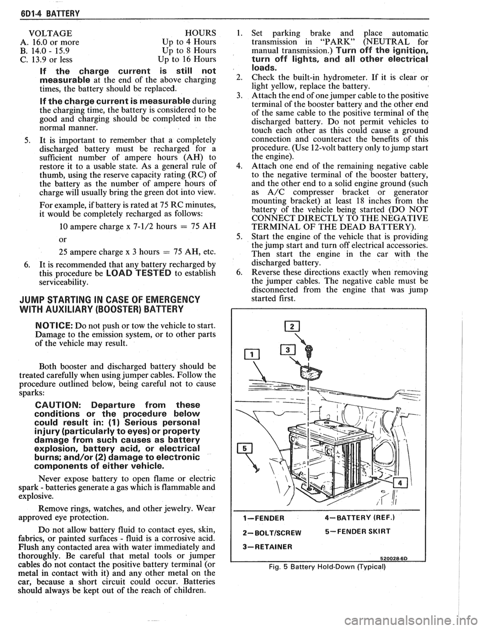
I-FENDER 4-BATTERY (REF.)
2- BOLTISCREW 5-FENDER SKIRT
3-RETAINER
520028-60
Fig. 5 Battery Hold-Down (Typical)