1988 PONTIAC FIERO ignition
[x] Cancel search: ignitionPage 130 of 1825
STEERING. SUSPENSION. TIRES AND WHEELS DIAGNOSIS 3-5
High Lock Effort
rn lnspect
e Lock cylinder damaged
e Ignition switch damaged
o Rack preload spring broken or deformed
e Burrs on sector, rack, housing, support or
actuator rod coupling
,
e Bent sector shaft
e Damaged rack
e Extreme misalignment of' housing to cover
e Distorted coupling slot in rack
e Bent actuator rod
e Ignition switch mounting bracket bent
e Actuator rod restricted
e Improper shift linkage adjustment
Will Stick In "Start"
rn lnspect
e Actuator rod deformed
e Check items under "High Lock Effort"
Key Cannot Be Removed in "Off-Lock"
rn lnspect
e Ignition switch is not set correctly
e Damaged lock cylinder
e Linkage mis-adjusted
Lock Cylinder Can Be Removed
Inspect
e Lock cylinder retaining screw missing
High Effort In Lock Cylinder Between "Off" and
"Off-Lock"
lnspect
o Distorted rack
Lock Bolt Hits Shaft Lock In "Off" Position and
"Park"
lnspect
e Ignition switch is not set correctly
COLUMN
Noise In Column
Inspect
e Joints from the column to the steering gear 1
e Column not correctly aligned
e Horn contact ring not lubricated
e Lack of grease on bearings
o Loose sight shields
o Lower or upper steering shaft bearing worn or
broken
e Shaft lock snap ring not seated
o Spherical joint not lubricated
High Steering Shaft Effort
e Column assembly misaligned
e Improperly installed or deformed dust seal
e Damaged upper or lower bearing
e Flash on I.D. of shift tube
e Tight intermediate steering shaft universal joint
High Shift Effort (Automatic with Column Shift)
rn lnspect
e Column not aligned correctly in car
e Wave washer with burrs
e Improperly installed dust seal
o Lack of grease on seal or bearing
e Improper screws used for ignition switch
e Burr on upper or lower end of shift tube
e Lower bowl bearing not assembled correctly
Improper Shifting (Automatic with Column
Shift)
rn lnspect
e Sheared shift tube joint or lower shift lever weld
e Improper or loose linkage adjustment
e 1,oose shift lever
e Improper gate plate
Lash In Steering Column
lnspect
e 1.P.-to-column upper and lower bracket
nlounting bolts loose
e Broken weld nuts on jacket
e I.P. upper bracket capsule sheared
e Loose shoes in housing
e Loose tilt head pivot pins
e Loose shoe lock pin in support
e Loose support screws
e Column upper and lower bracket-to-jacket bolts
loose
e Loose lower bracket-to-adapter and bearing
assembly mounting screws
e Loose 1.P.-to-jacket mounting bolts
Housing Scraping On Bowl
rn Inspect
e Bowl bent or not concentric with hub
e Cover and housing end cap not properly installed
Page 132 of 1825
STEERING, SUSPENSION, TIRES AND WHEELS DIAGNOSIS 3-7
e To determine if turn signal switch is inoperative,
substitute new turn signal switch into circuit and
operate switch by hand.
If the car's lights operate
normally, turn signal switch is inoperative.
Front Or Rear Turn Signal Lights Not Flashing
Inspect
s Burned-out or damaged turn signal bulb
e High resistance conection to ground at bulb
socket
s Loose chassis-to-column connector. Disconnect
column-to-chassis connector and connect new
turn signal switch into system and operate switch
by hand.
A. If turn signal lights are now on and flashing,
turn signal switch is inoperative.
B. If car lights do not operate, refer to Section
8A
for electrical diagnosis.
Turn Indicator Panel Lights
Inspect
Burned out bulbs or opens, grounds in the wiring
harness from the front turn signal bulb socket to the
indicator lights. Refer to Section
8A for electrical
diagnosis.
Stop Light Mot On When Turn Indicated
Inspect
s Loose column-to-chassis connection
e Disconnect the column-to-chassis connector and
connect the new turn signal switch into the
system and operate the switch by hand.
A. If the brake lights work when the switch is
in the turn position, the turn signal switch
is inoperative.
B. If the brake lights do not work, refer to Section
8A for electrical diagnosis.
Turn Signal Lights Flash Very Slowly
e Loose chassis-to-column connection
a Disconnect the column-to-chassis connector and
connect a new turn signal switch into the system
and operate the switch by hand.
A. If the lights flash at a normal rate, the turn
signal switch is inoperative.
B. If the Lights still flash very slowly, refer to
Section
8A for electrical diagnosis.
Hazard Signal Lights Will Not Flash - Turn
Signal Functions Normally
~"SPBC~
a Blown fuse
Inoperative hazard warning flasher
e Loose chassis-to-column connection
s Disconnect the column-to-chassis connector and
connect a new turn signal switch into the system,
then press in the hazard warning button and
watch the hazard warning lights.
A. If the lights now work normally, the turn
signal switch is inoperative.
B. If the lights do not flash, check the wiring
harness. Refer to Section
8A for electrical
diagnosis.
IGNITION SWITCH
Electrical System Will Not Function
Damaged ign~rion switch
e Ignition switch not adjusted properly
e Loose connector at the ignition switch
Switch Will Not Turn
Inspect
Damaged ignition switch
Switch Cannot Be Set Correctly
Inspect
Switch actuator rod deformed
e Sector to rack engaged in wrong tooth
KEY REMINDER
Figs. 1 through 11 ,
Weminder Continues To Operate With Key Out,
But Stops When Driver's Door Is Closed
e Chips, foreign material in lock cylinder bore
Sticky lock cylinder actuator tip
Damaged or broken reminder switch
Reminder Does Not Sound With Key Fully
Inserted In Lock Cylinder And The Driver's Door
Open
Inspect
1. Power not available to reminder. Refer to Sec-
tion
8A for electrical diagnosis.
2. Open in chassis wiring. Check by separating
chassis-to-column connector. Connect terminals
"E" and "F" female contacts on the chassis
connector (a bent paper clip will work). If the
reminder sounds, repair chassis wiring. If the
reminder does not sound, go to Step
A.
A. Connect a continuity meter (light) to the
male
"E" and "F" column connector
contacts. Push the key all the way into the
lock cylinder. If the light is on when the key
Page 152 of 1825
STEERING WHEELS AND COLUMNS 385.1
SECTION 3B5
STEER NG WHEELS AND COLUMNS
NOTICE: All steering wheel and column fasteners are important attaching parts in that they could affect
the performance of vital parts and systems, and/or could result in major repair expense. They
must be replaced
with one of the same part number or with an equivalent part if
replacement becomes necessary. Do not use a
replacement part of lesser quality or substitute design. 'Torque values must be used as specified during reassembly
to assure proper retention of all parts. There is to be no welding as
it may result in extensive damage and weakening
of the metal.
For prevailing torque
nut(s) and bolts(s), refer to the "Reuse of Prevailing Torque Nut(<) and Bolt(s) " chart
in Section OA.
CONTENTS
..................... ................................................................... GENERAL DESCRIPTION .. 3B5-1 ............................................. ........................ MAINTENANCE AND ADJUSTMENTS .. 3B5-1 ON-CAR SERVICE ........................................................................................................ 3B5-2
Steering Column ............................................................................................................ 3B5-2 ......................................................................................................... Intermediateshaft 3B5-3
Park Lock Cable .................................................................... 3B54 ......................................................................................... Checking For Accident Damage 3B5-5 ............................................................................ Unit Repair Intermediate Shaft Assembly 3B5-6
..................................................................................... Standard Column @lanual Trans) 3B5-7 ......................................................... ....................... Standard Column (Auto Trans) .. 3B5-13 Tilt Column (Manual Trans) ............................................................................................. 3B5-19
Tilt Column (Auto Trans). ................................................................................................ 3B5-27
................ .................... TORQUE SPECIFICATIONS .. .. 3B5-35
SPECIAL TOOLS .......................................................................................................... 3B5-35
GENERAL DESCRIPTION
STEERING COLUMN
The function locking energy absorbing steering
column includes three important features in addition
to the steering function:
1. 'The column is energy absorbing, designed to
compress in a front-end collision to minimize the
possibility of an injury to the driver of the car.
2. The ignition switch and lock are mounted
conveniently on this column.
3. With the column mounted lock, the ignition and
steering operations can be locked to inhibit theft
of the car.
The turn signal lever provides for control of
headlight beams, windshield washer and wipers.
The column may be easily
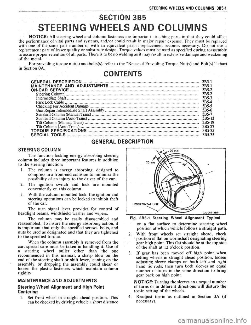
disassembled and Fig. 385-1 Steering Wheel Alignment ~ypical
reassembled. To insure the energy absorbing action, it
on a flat surface to determine steering wheel
is important that only the specified screws, bolts, and
position at which vehicle follows a straight path.
nuts be used as designated and that they are tightened
2. With front wheels set straight ahead, check to the specified torque.
position of flat on wormshaft designating steering
When the column assembly is removed from the
gear high point. This flat should be at the top side
car, special care must be taken in handling it. Use of
of the shaft at 12 o'clock position.
a steering puller other than the One 3, if gear has been moved off high when recommended in this manual, a sharp blow on the
setting wheels in straight ahead position, loosen
end of the steering shaft or shift lever, leaning on the
assembly, or dropping the assembly could shear or adjusting
sleeve clamps on both left and right
hand tie rods, then turn both sleeves an equal
loosen the plastic fasteners which maintain column
rigidity. number
of turns in the same direction
to bring
gear back
on high point.
MAINTENANCE AND ADJUSTMENTS NOTICE: Turning the sleeves an unequal number
Steering Wheel Alignment and High Point of turns or in different directions will disturb the
Centering toe-in setting of the wheels.
1. Set front wheel in straight ahead position, This 3. Readjust toe-in as outlined in Section 3A (if
can be checked by driving vehicle
a short distance necessary).
Page 153 of 1825
385-2 STEERING WHEELS AND COLUMNS
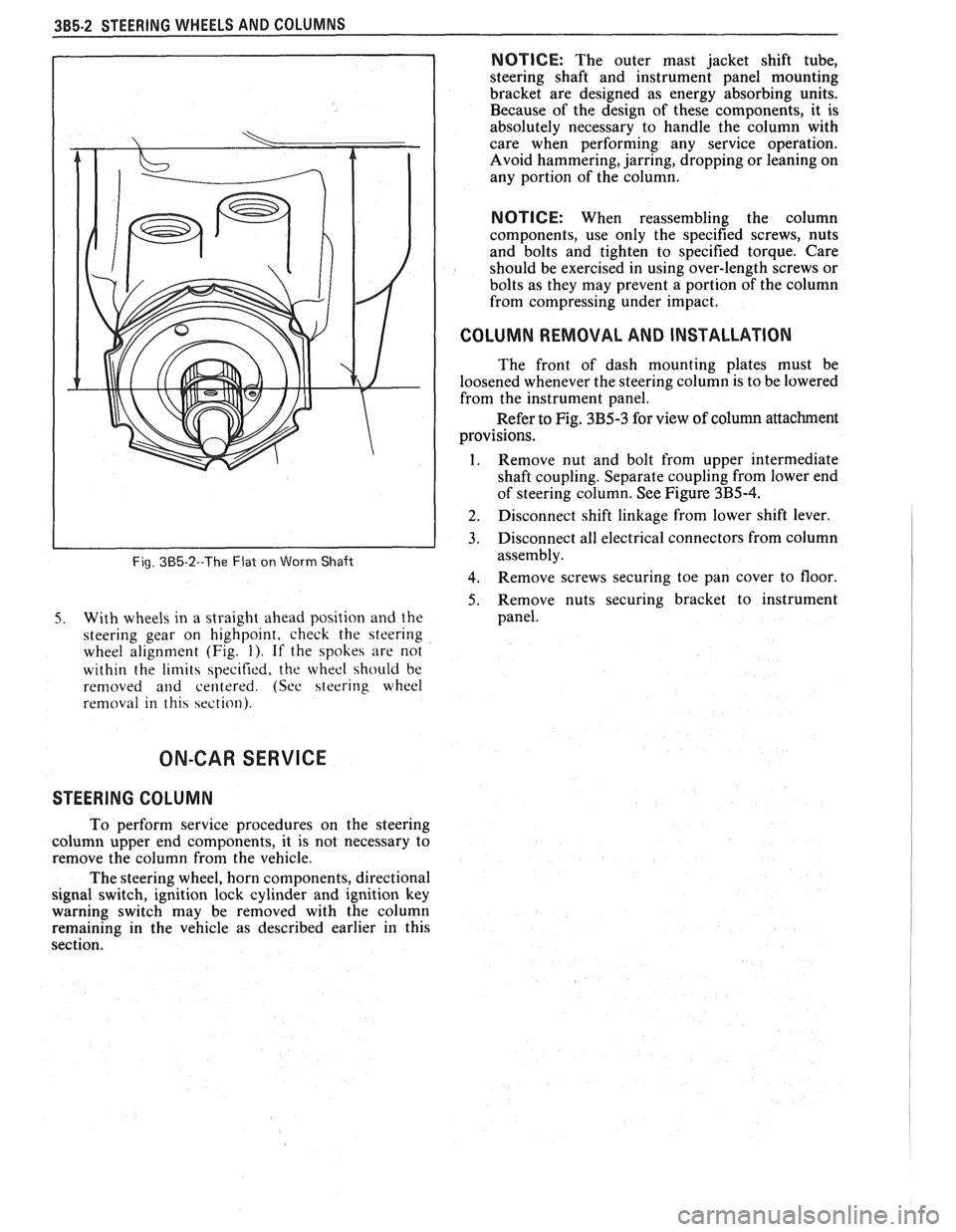
Fig. 385-2--The Flat on Worm Shaft
5. With wheels in a straight ahead position and the
steering gear on highpoint, check the steering
wheel alignment (Fig.
1). If the spokes are not
within the
limits specified, the wheel should be
removed
and centered. (See steering wheel
removal in this section).
NOTICE: The outer mast jacket shift tube,
steering shaft and instrument panel mounting
bracket are designed as energy absorbing units.
Because of the design of these components, it is
absolutely necessary to handle the column with
care when performing any service operation.
Avoid hammering, jarring, dropping or leaning on
any portion of the column.
NOTICE: When reassembling the column
components, use only the specified screws, nuts
and bolts and tighten to specified torque. Care
should be exercised in using over-length screws or
bolts as they may prevent a portion of the column
from compressing under impact.
I COLUMN REMOVAL AND INSTALLATION
The front of dash mounting plates must be
loosened whenever the steering column is to be lowered
from the instrument panel.
Refer to Fig. 3B5-3 for view of column attachment
provisions.
1. Remove nut and bolt from upper intermediate
shaft coupling. Separate coupling from lower end
of steering column. See Figure
3B5-4.
] 2. Disconnect shift linkage from lower shift lever.
3. Disconnect all electrical connectors from column
assembly.
4. Remove screws securing toe pan cover to floor
5. Remove nuts securing bracket to instrument
panel.
ON-CAR SERVICE
STEERING COLUMN
To perform service procedures on the steering
column upper end components, it is not necessary to
remove the column from the vehicle.
The steering wheel, horn components, directional
signal switch, ignition lock cylinder and ignition key
warning switch may be removed with the column
remaining in the vehicle as described earlier in this
section.
Page 161 of 1825
385.10 STEERING WHEELS AND COLUMNS
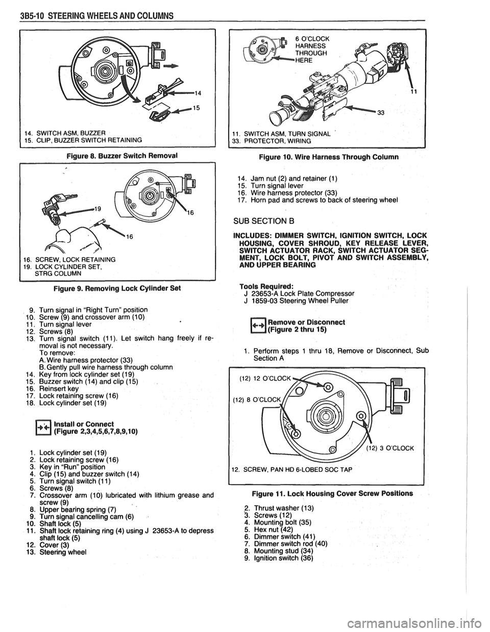
Figure 8. Buzzer Switch Removal
1 16. SCREW. LOCK RETAINING I 19. LOCK CYLINDER SET, I STRG COLUMN I
Figure 9. Removing Lock Cylinder Set
9. Turn signal in "Right Turn" position
10. Screw (9) and crossover arm (10)
11. Turn signal lever
12. Screws (8)
13. Turn signal switch (1 1). Let switch hang freely if re-
moval is not necessary.
To remove:
A. Wire harness protector (33)
6. Gently pull wire harness through column
14. Key from lock cylinder set (1 9)
15. Buzzer switch (1 4) and clip (1 5)
16. Reinsert key
17. Lock retaining screw (1 6)
18. Lock cylinder set (1 9)
Install or Connect
(Figure 2,3,4,5,6,7,8,9,10)
1. Lock cylinder set (1 9) 2. Lock retaining screw (1 6)
3. Key in "Run" position
4. Clip
(1 5) and buzzer switch (1 4)
5. Turn signal switch (1 1)
6. Screws (8)
7. Crossover arm (10) lubricated with lithium grease and
screw (9)
8. Upper bearing spring
(7) 9. Turn signal cancelling cam (6)
10. Shaft lock (5) 11. Shaft lock retaining ring (4) using J 23653-A to depress
shaft lock (5) 12. Cover (3) 13. Steering wheel
Figure 10. Wire Harness Through Column
14. Jam nut (2) and retainer (1)
15. Turn signal lever
16. Wire harness protector (33)
17. Horn pad and screws to back of steering wheel
SUB SECTION B
INCLUDES: DIMMER SWITCH, IGNITION SWITCH, LOCK
HOUSING, COVER SHROUD, KEY RELEASE LEVER,
SWITCH ACTUATOR RACK, SWITCH ACTUATOR SEG-
MENT, LOCK BOLT, PIVOT AND SWITCH ASSEMBLY,
AND UPPER BEARING
Tools Required:
J 23653-A Lock Plate Compressor J 1859-03 Steering Wheel Puller
++ Remove or Disconnect
(Figure 2 thru 15)
1. Perform steps 1 thru 18, Remove or Disconnect, Sub
Section A
(12) 12 O'CLOCK
12. SCREW, PAN HD
&LOBED SOC TAP
Figure 11. Lock Housing Cover Screw Positions
2. Thrust washer (1 3) 3. Screws (1 2)
4. Mounting bolt (35)
5. Hex nut (42)
6. Dimmer switch (41)
7. Dimmer switch rod (40)
8. Mounting stud (34)
9. Ignition switch (36)
Page 162 of 1825
STEERING WHEELS AND COLUMNS 3B5-11
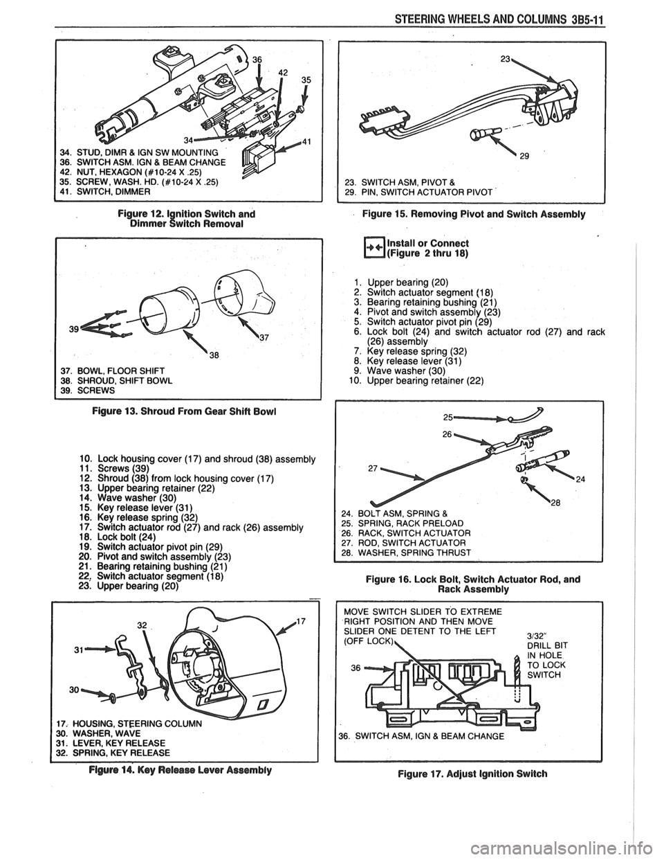
Figure 12.1 nition Switch and
Figure 15. Removing Pivot and Switch Assembly Dimmer twitch Removal
37. BOWL, FLOOR SHIFT 38. SHROUD, SHIFT BOWL
Install or Connect
(Figure 2 thru 18)
1. Upper bearing (20)
2. Switch actuator segment (1 8)
3. Bearing retaining bushing (21)
4. Pivot and switch assembly (23)
5. Switch actuator pivot pin (29)
6. Lock bolt (24) and switch actuator rod (27) and rack
(26) assembly
7. Key release spring (32)
8. Key release lever (31)
9. Wave washer (30)
10. Upper bearing retainer (22)
Figure
13. Shroud From Gear Shift Bowl
10. Lock housing cover (1 7) and shroud (38) assembly
11. Screws (39)
12. Shroud (38) from lock housing cover (1
7) 13. Upper bearing retainer (22)
14. Wave washer (30)
15. Key release lever (31
) 16. Key release spring (32)
17. Switch actuator rod (27) and rack (26) assembly
18. Lock bolt (24)
19. Switch actuator pivot pin (29)
20. Pivot and switch assembly (23)
21. Bearing retaining bushing (21
) 22, Switch actuator segment (1 8)
Figure 16. Lock Bolt, Switch Actuator Rod, and
23. Upper bearing (20)
Rack Assembly
17
17: HOUSING. STEERING COLU 30. WASHER, WAVE 31. LEVER, KEY RELEASE 32. SPRING, KEY RELEASE RIGHT
POSITION AND THEN MOVE
SLIDER ONE DETENT TO THE
LEFT
Flgurs 14. Key Release Lever Assembly
Figure 17. Adjust Ignition Switch
Page 165 of 1825
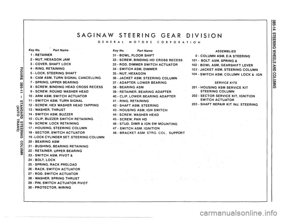
SAGINAW STEERING GEAR DIVISION
GENERAL MOTORS CORPORATION
Key No. Part Name
1 - RETAINER
2
- NUT, HEXAGON JAM
3
- COVER, SHAFT LOCK
4
- RING, RETAINING
5
- LOCK, STEERING SHAFT
6
- CAM ASM, TURN SIGNAL CANCELLING
7
- SPRING, UPPER BEARING
8
- SCREW, BINDING HEAD CROSS RECESS
9 - SCREW, ROUND WASHER HEAD
10
- ARM ASM, SWlTCH ACTUATOR
11
- SWITCH ASM, TURN SIGNAL
12
- SCREW, HEX WASHER HEAD TAPPING
13
- WASHER, THRUST
14
- SWITCH ASM, BUZZER
15
- CLIP, BUZZER SWITCH RETAINING
16
- SCREW, LOCK RETAINING
17
- HOUSING, STEERING COLUMN
18
- SECTOR, SWITCH ACTUATOR
19 -LOCK CYLINDER SET, STEERING COLUMN
20
- BEARING ASM
21
- BUSHING, BEARING RETAINING
22
- RETAINER, UPPER BEARING
23
- SWITCH ASM, PIVOT &
24 - BOLT, LOCK
25
- SPRING, RACK PRELOAD
26
- RACK. SWlTCH ACTUATOR
27 - ROD, SWITCH ACTUATOR
28
- WASHER. SPRING THRUST
29 - PIN, SWITCH ACTUATOR PIVOT
30
- PROTECTOR, WIRING
Key No. Part Name ASSEMBLIES
31 - BOWL, FLOOR SHIFT
0 - COLUMN ASM, E/A STEERING
32
- SCREW, BINDING HD CROSS RECESS
101 - BOLT ASM, SPRING &
33 - ROD, DIMMER SWITCH ACTUATOR
102 - BOWL ASM. GEARSHIFT LEVER
34
- SWITCH ASM, DIMMER
103 - JACKET ASM, STEERING COLUMN
35
- NUT, HEXAGON 104 - SWITCH ASM, COLUMN LOCK & IGN
36 - JACKET ASM, STEERING COLUMN
37
- ADAPTER, LOWER BEARING SERVlCE KITS
38 - BEARING ASM 201 - HOUSING ASM SERVICE KIT
39
- RETAINER, BEARING ADAPTER STEERING
COLUMN
40
- CLIP. LOWER BEARING ADAPTER 202 - SECTOR SERVICE
KIT, IGNITION
41
- RING. RETAINING SWITCH
ACTUATOR
42
- SHAFT ASM, STEERING 203 - SHAFT
REPAIR KIT INJ. STEERING
43
- HOUSING ASM, IGN SWITCH
44
- SCREW. WSHER HEAD
45
- SCREW, PAN HD
46
- STUD, DlMR & IGN SW MOUNTING
47
- SWITCH ASM, IGNITION
48 - BRACKET ASM. STRG. COL. SUPPORT
Page 167 of 1825
385-16 STEERING WHEELS AND COLUMNS
5. Shaft assembly (42) to column 6. Bearing spring (7)
7. Turn signal cancelling cam (6)
8. Shaft lock (5) and cover (3) 9. Shaft lock retaining ring (4) using J 23653-A to depress
shaft lock (5) 10. Column to dash 1 1. Steering wheel 12. Jam nut (2) 13. Retainer (1) 14. Horn pad
SUB SECTION Ej
INCLUDES: DIMMER SWITCH, IGNITION SWITCH, AND
DIMMER SWITCH ROD
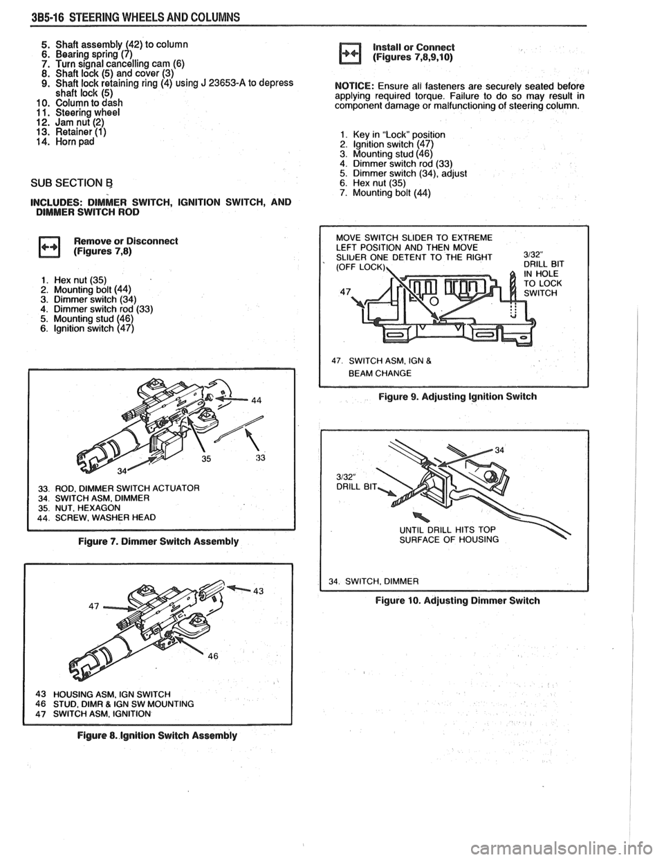
Remove or Disconnect
(Figures
7,8)
1. Hex nut (35)
2. Mounting bolt (44)
3. Dimmer switch (34) 4. Dimmer switch rod (33)
5. Mounting stud (46)
6. lgnition switch (47)
Figure 7. Dimmer Switch Assembly
IGN SW MOUNTING
Figure 8. lgnition Switch Assembly install
or Connect
(Figures
7,8,9,10)
NOTICE: Ensure all fasteners are securely seated before
applying required torque. Failure to do so may result in
component damage or malfunctioning of steering column.
1. Key in "Lock" posit~sn 2. lgnltion switch (47)
3. Mounting stud (46)
4. Dimmer switch rod (33)
5. Dimmer switch (34), adjust 6. Hex nut (35) 7. Mounting bolt (44)
47 SWITCH ASM. IGN 8
Figure 9. Adjusting Ignition Switch
UNTIL DRILL HITS TOP
SURFACE OF HOUSING
34 SWITCH. DIMMER I
Figure 10. Adjusting Dimmer Switch