1988 PONTIAC FIERO ignition
[x] Cancel search: ignitionPage 296 of 1825
BRAKES 5-3
DIAGNOSIS AND INSPECTION
BRAKE SYSTEM TESTING
(Figures
2 through 4)
Brakes should be tested on dry, clean, reasonably
smooth and level roadway. A true test of brake performance
cannot be made if the roadway is wet, greasy or covered
with loose dirt so that all tires do not grip the road equally.
Testing will also be affected if the roadway is crowned
which would throw the weight of the car toward the wheels
on one side. If the roadway is too rough, the wheels will tend
to bounce. Test brakes at different car speeds with both light and
heavy pedal pressure, avoid locking the brakes and sliding
the tires. Locked brakes and sliding tires do not indicate
brake efficiency, because heavily braked, but turning
wheels will stop the car in less distance than locked brakes.
More tire-to-road friction is present with a heavily braked
turning tire than with a sliding tire. The brake system is designed and balanced to avoid
locking the wheels, except at very high deceleration levels.
The shortest stopping distance and best control is achieved
without brake lock-up.
Because of high deceleration capability, a firmer pedal
may be felt at higher deceleration levels.
External Conditions That Affect Brake Performance
1. Tires. Tires having unequal contact and grip on road
will cause unequal braking. Tires must be equally
inflated and tread pattern of right and left tires must
be approximately equal.
2. Car Loading. A heavily loaded car requires more
braking effort. When a car has unequal loading, the
most heavily loaded wheels require more braking
power than others.
3. Wheel Alignment. Misalignment of the wheels, par-
ticularly excessive camber and caster, will cause the
brakes to pull to one side.
4. Front Wheel Bearings. A loose front wheel bearing
BRAKE FLUID LEAKS
With engine running at idle and the transmission in neu-
tral, depress the brake pedal and hold a constant foot pres-
sure.
If the pedal gradually falls away with the constant
pressure, the hydraulic system may be leaking. Perform a
visual check to confirm any suspected leak.
Check the master cylinder fluid levels. While a slight drop
in reservoir level does result from normal lining wear, an
abnormally low level in either reservoir indicates
a leak in
the system. The hydraulic system may be leaking either
internally or externally. See "Master Cylinder Check."
Also, the system may appear to pass this test but still have
slight leakage.
If fluid levels are normal, check the vacuum booster
pushrod length. If an incorrect length pushrod is found,
adjust or replace the
pushrod. Check the service brake
pedal travel and the parking brake adjustment.
When checking the fluid levels, the master cylinder reser-
voir may be as low as
25 mm (1 inch) from the top if the front
linings are worn. This is not abnormal.
MASTER CYLINDER CHECK
These checks will help locate some master cylinder mal-
functions. Use the Brake Diagnosis Charts to help isolate
the problem if it is not found by using these tests.
1. Check for a cracked master cylinder casting or brake
fluid around the master cylinder. Leaks are indicated
only if there is at least a drop of fluid. A damp condi-
tion is not abnormal.
2. Check for a binding pedal linkage.
3. Disassemble the master cylinder and check for swol-
len or stretched piston
seal(s). If swollen seals are
found, substandard or contaminated brake fluid
should be suspected.
If contaminated, all compo-
nents should be disassembled and cleaned. All rub-
ber components should be replaced and all the pipes
should be flushed.
permits the front wheel to tilt and lose contact with the
SUBSTANDARD OR CONTAMINATED brake shoe linings causing erratic brake operation. BRAKE FLUID
WARNING LAMP OPERATION
The brake system uses a single red "BRAKE" warning
lamp located in the instrument panel cluster. When the
ignition switch is in the "START" position, the "BRAKE"
warning lamp should come on. It should go off when the
ignition switch returns to the "RUN" position.
The following conditions will activate the "BRAKE"
warning lamp:
1. Parking brake applied. The lamp should be on when
tfie parking brake is applied and the ignition switch is
"ON."
2. Pressure differential switch detects a failure. See
"Brake Pressure Differential Warning Switch" in this
section. Improper
brake fluid, mineral oil or water in the fluid may
cause the brake fluid to boil or the rubber components to
deteriorate.
If piston cups are swollen, the rubber parts have dete-
riorated. This deterioration may also be seen by swollen
wheel cylinder piston cups on the drum brake wheels or a
swollen master cylinder cover diaphragm.
If rubber deterioration is evident, disassemble all hydrau-
lic parts and wash with alcohol. Dry these parts with com-
pressed air before assembly to keep alcohol out of the
system. Replace all rubber parts in the system, including
hoses. Check for fluid on the linings. If excessive fluid is
found, replace the linings.
If master cylinder piston seals are satisfactory, check for
leakage or excessive heat conditions. If condition is not
found, drain fluid, flush with brake fluid, fill and bleed the
system.
Page 310 of 1825
BRAKES 5-17
maintaining proper wheel balance, brake drums should be
checked for balance. Brake drums may be checked for
balance on most off-the-car balancers.
COMBINATION VALVE
Testing Combination Valve Electrical Circuit
When removing the electrical wire connector from the
pressure differential switch, squeeze the
eliptical shaped
plastic locking ring and pull up. This will move the locking
tangs away from the switch. Pliers can be used to help
remove the connector.
1. Disconnect wire from switch terminal and use a
jumper to connect wire to a good ground.
2. Turn ignition key to "ON." The warning lamp should
light. If lamp does not light, bulb is burned out or
electrical circuit is faulty. Replace bulb or repair elec-
trical circuit as necessary.
3. When warning lamp lights, turn off ignition switch.
Disconnect jumper and connect wire to switch termi-
nal.
Testing Combination Valve Warning Lamp Switch
1. Attach a bleeder hose to a rear brake bleed screw and
immerse the other end of the hose in a container
partially filled with clean brake fluid. Be sure master
cylinder reservoirs are full.
2. Turn ignition switch to "ON." Open bleeder screw
while an assistant applies moderate pressure to the
brake pedal. Warning lamp should light. Close
bleeder screw before assistant releases brake pedal.
Apply brake pedal with moderate-to-heavy pressure.
Lamp should go out.
3. Attach the bleeder hose to a front brake bleeder
screw and repeat steps
1 and 2. Warning lamp action
should be the same as in step
2. Turn off ignition
switch.
4. If warning lamp does not light during steps 2 and 3,
but does light when a jumper is connected to ground,
the warning lamp switch portion of the combination
valve is faulty. Do not disassemble the combination
valve.
If any portion of the combination valve is faulty,
it must be replaced with a new combination valve.
Combination Valve Replacement
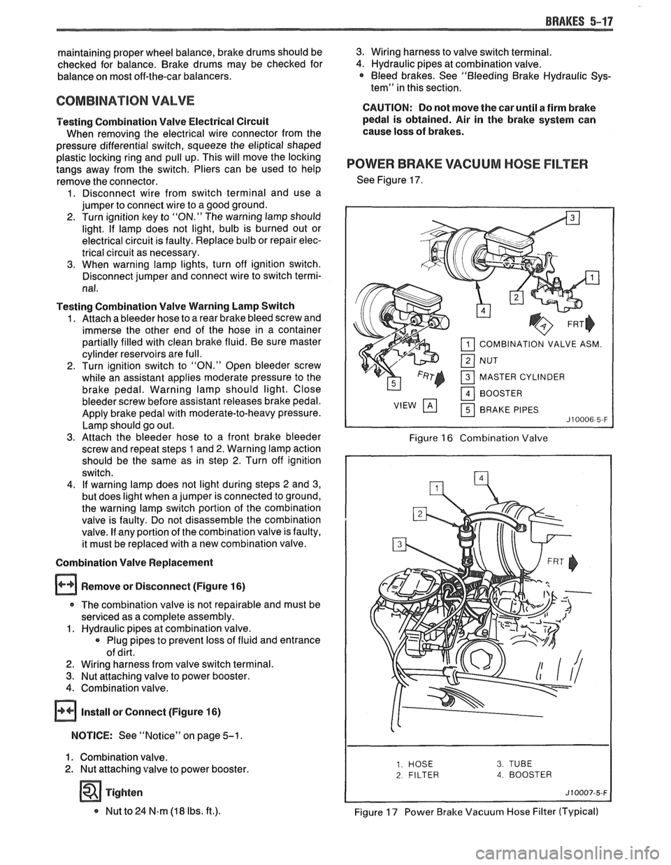
Remove or Disconnect (Figure
16)
r The combination valve is not repairable and must be
serviced as a complete assembly.
1. Hydraulic pipes at combination valve.
Plug pipes to prevent loss of fluid and entrance
of dirt.
2. Wiring harness from valve switch terminal.
3. Nut attaching valve to power booster.
4. Combination valve.
@ Install or Connect (Figure 16)
NOTICE: See "Notice" on page 5-1.
1. Combination valve.
2. Nut attaching valve to power booster.
Tighten
* Nut to 24 N.m (18 Ibs. ft.).
3. Wiring harness to valve switch terminal.
4. Hydraulic pipes at combination valve. * Bleed brakes. See "Bleeding Brake Hydraulic Sys-
tem" in this section.
CAUTION: Do not move the car until a firm brake
pedal is obtained. Air in the brake system can
cause loss of brakes.
POWER BRAKE VACUUM HOSE FILTER
See Figure 17.
COMBINATION VALVE ASM.
MASTER CYLINDER BRAKE PIPES
Figure 16 Combination Valve
2 FILTER 4. BOOSTER
Figure 17 Power Brake Vacuum Hose Filter (Typical)
Page 324 of 1825
DISC BRAKE CALIPER ASSEMBLY 588-3
BO LT
FITTING
MOUNTING
31. BRAKE PIPE
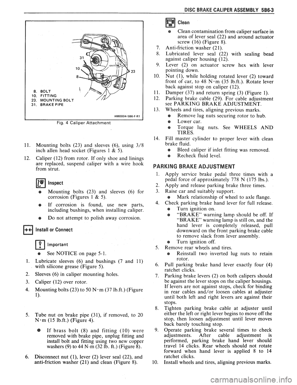
Fig. 4 Caliper Attachment
11. Mounting bolts (23) and sleeves (6), using 3/8
inch
allen head socket (Figures 1 & 5).
12. Caliper (12) from rotor. If only shoe and linings
are replaced, suspend caliper with a wire hook
from strut.
Inspect
e Mounting bolts (23) and sleeves (6) for
corrosion (Figures
1 & 5).
e If corrosion is found, use new parts,
including bushings, when installing caliper.
e Do not attempt to polish away corrosion.
Install or Connect
Important
See NOTICE on page 5- 1.
1. Lubricate sleeves (6) and bushings (7 and 11)
with silicone grease (Figure 5).
2. Sleeves
(6) in caliper mounting holes.
3. Caliper (12) over rotor.
4. Mounting bolts (23) to 50 N-m (37 1b.ft.) (Figure
1).
5.
Tube nut on brake pipe (31), if removed, to 20
N-m (15 1b.ft.) (Figure 4).
@ If brass bolt (8) and fitting (10) were
removed with brake pipe, unplug fitting and
install bolt and fitting using two new copper
washers
(9) to 44 N.m (32 lb. ft.) (Figure 8).
6. Disconnect nut (I), lever (2) lever seal (22), and
anti-friction washer (21) and clean (Figure 8).
Clean
Clean contamination from caliper surface in
area of lever seal (22) and around actuator
screw (16) (Figure 8).
7. Anti-friction washer (21).
8. Lubricated lever seal (22) with sealing bead
against caliper housing (12).
9. Lever (2) on actuator screw hex with lever
pointing down.
10. Nut
(I), while holding rotated lever (2) toward
front of car, to 48
N-m (35 1b.ft.). Rotate lever
back against stop on caliper (12).
11. Damper (37) and return spring (3) (Figure 1).
12. Parking brake cable (29). For cable adjustment
see PARKING BRAKE ADJUSTMENT.
13. Wheels and tires, aligning previous marks.
s Remove lug nuts securing rotor to hub.
e Lower car.
e Torque lug nuts. See WHEELS AND
TIRES.
14. Fill master cylinder to proper lever with clean
brake fluid.
e Bleed caliper if inlet fitting was removed.
Recheck fluid level.
PARKING BRAKE ADJUSTMENT
Apply service brake pedal three times with a
pedal force of approximately 778 N (175 lbs.).
Apply and release parking brake three times.
Raise car and suitably support.
e Mark relationship of wheel to axle flange.
Check parking brake hand lever for full release.
e Turn ignition on.
e "BRAKE" warning lamp should be off. If
"BRAKE" warning lamp is still on, and the
hand lever is completely released, pull
downward on the front parking brake cable
to remove slack from lever assembly.
Turn ignition off.
Remove rear wheels and tires.
e Reinstall two inverted lug nuts to retain
rotor.
Pull parking brake hand lever exactly four (4)
ratchet clicks.
Parking brake levers (2) on both calipers should
be against the lever stops on the caliper housings.
If levers are not against stops, check for binding
in rear cables and/or loosen cables at adjuster
until both left and right levers are against their
stops.
Tighten parking brake cable at adjuster until
either the left or right lever begins to move off the
stop, then loosen adjustment until lever moves
back barely touching stop.
Operate parking brake several times to check
adjustments. After cable adjustment is
performed, parking brake hand lever should
travel 14 clicks. Rear wheels should not rotate
forward when hand lever is applied
8 to 14
ratchet clicks.
Install wheels and tires, aligning previous marks.
Page 346 of 1825
ENGINE GENERAL INFORMATION 6-1
SECTION 6
NE GENERAL NFORMAT
Description ............................................................... 6 TBI ...................................... .. ...... 6E2 ................ Engine Mechanical Multi Port Fuel Injection (MPFI) 6E3 -
............................................... 2.8L V-6 ....................................................... 6A2 Exhaust Systems 6F
5.OL V-8 ......................................................... 6A3 ~~~~~~l ~~f~~~~ti~~ ..................................... 6-2
............................ Engine Cooling ...................................................... 6B Engine Performance Diagnosis 6-3 ............................. Engine Fuel 6C Engine Mechanical Diagnosis
6-3 ........................................................... ................................... Engine Knock Diagnosis 6-4
Engine Electrical ................................................... 6D Compression Test ...................................... ... 6-5
................... Driveability and Emission Controls ...................... 6E Oil Leak Detection .. ..................... 6-5
ALL NEW GENERAL MOTORS VEHICLES ARE CERTIFIED BY THE UNITED STATES
ENVIRONMENTAL PROTECTION AGENCY AS CONFORMING TO THE REQUIREMENTS OF
THE REGULATIONS FOR THE CONTROL OF AIR POLLUTION FROM NEW MOTOR VEHICLES.
THlS CERTIFICATION IS CONTINGENT ON CERTAIN ADJUSTMENTS BEING SET TO
FACTORY STANDARDS. IN MOST CASES, THESE ADJUSTMENT POINTS EITHER HAVE
BEEN PERMANENTLY SEALED AND/OR MADE INACCESSIBLE TO PREVENT
INDISCRIMINATE OR ROUTINE ADJUSTMENT IN THE FIELD. FOR
THlS REASON, THE
FACTORY PROCEDURE FOR TEMPORARILY REMOVING PLUGS, CAPS, ETC., FOR
PURPOSES OF SERVICING THE PRODUCT MUST BE STRICTLY FOLLOWED AND,
WHEREVER PRACTICABLE, RETURNED TO THE ORIGINAL INTENT OF THE DESIGN.
DESCRIPTION OF: SECTION 6
SECTION 6A - ENGINE MECHANICAL used for each carburetor. TBI units are described in
This section general contains information on the Section 6E.
mechanical parts of the engine, such as block,
crankshaft, pistons, valve train, and camshaft, that are
common to most engines. Overhaul procedures,
removal and replacement procedures, and
s~ecifications are also covered. Subsections furnish
detailed information on each specific engine. Service
SECTION 6D - ENG l N E ELECTRICAL
information is also given that relates to that engine's
use in each
Carline. Specific subsections are: Items
covered in this section are battery,
generator, starter, primary and secondary ignition,
6A2
- 2.8L V-6 Engine
engine wire harness, spark plugs and wires, and
6A3
- 5.OL V-8 Engine
ignition switch.
SECTION 6B - ENGINE COOLING
Engine cooling system components such as
radiator, water pump, thermostat, and cooling fan, are
covered in this section. Accessory drive belts are also
covered, along with cooling system capacities.
SECTION 6C - FUEL SYSTEM
This section contains information on all the parts
of the fuel system
except the carburetor, or Throttle
Body Injection unit (TBI) itself. Items covered are fuel
tank, fuel pump, and fuel lines. Specific subsections are
SECTION 6E - DRIVEABILITY AND EMISSIONS
This section covers emission control systems
general information, and diagnostic procedures which
will lead to repairing performance and driveability
related problems for gasoline engine equipped vehicles.
All emission components are covered, as well as all
removal and replacement procedures. Instructions on
use of special tools are also given. Specific sections are:
6E
- Driveability and Emissions
6E2
- Fuel Injection (TBI)
Page 347 of 1825
6-2 ENGINE GENERAL INFORMATION
6E3 - Fuel Injection (Ported) This section has information
on all exhaust
system parts, such as tailpipes, mufflers, and the
SECTION 6F - EXHAUST SYSTEM catalytic converter.
GENERAL INFORMAflION
CLEANLINESS AND CARE
An automobile engine is a combination of many
machined, honed, polished and lapped surfaces with
tolerances that are measured in the ten-thousandths of
an inch. When any internal engine parts are serviced,
care and cleanliness are important. A liberal coating of
engine oil should be applied to friction areas during
assembly, to protect and lubricate the surfaces on
initial operation. Throughout this section, it should be
understood that proper cleaning and protection of
machined surfaces and friction areas is part of the
repair procedure. This is considered standard shop
practice, even if not specifically stated. PREVENTING
DAMAGE AND IN
CONTRIBUTING TO RELIABLE ENGINE
PERFORMANCE.
When raising or supporting the engine for any
reason, do not use a jack under the oil pan. Due to the
small clearance between the oil pan and the oil pump
screen, jacking against the oil pan may cause it to be
bent against the pump screen resulting in a damaged
oil pick-up unit.
When working on the engine, remember that the
12-volt electrical system is capable of causing short
circuits. When performing any work where electrical terminals could possibly be grounded, the ground cable
of the battery should be disconnected at the battery.
Any time the carburetor or air cleaner is
train components are removed removed, the intake opening should be covered. This for service, they should be in order' will protect against entrance of foreign be installed in the same locations, and with the same material, which could follow the intake passage into mating surfaces, as when removed
the cylinder and cause extensive damage when the -
Battery cables should be disconnected before any engin; is started.
major work is performed on the engine. Failure to IN THE MECHANICAL PROCEDURES
disconnect cables may result in damage to wire harness DESCRIBED IN THIS SECTION, GENERALLY
or other electrical parts. NO
REFERENCES WILL BE MADE TO THE
REMOVAL OF OPTIONAL EQUIPMENT SUCH
ENGINE SERVICE AS POWER STEERING PUMP, AIR
CONDITIONING COMPRESSOR, ETC.
THE FOLLOWING INFORMATION ON SHOULD IT BECOME NECESSARY TO
ENGINE SERVICE SHOULD BE NOTED REMOVE ANY SUCH ITEM TO
PERFORM
CAREFULLY, AS IT IS IMPORTANT IN OTHER SERVICE, REFER TO THE
APPROPRIATE SECTION OF THIS SERVICE
MANUAL FOR SPECIFIC INFORMATION.
ENGINE PERFORMANCE DIAGNOSIS
INTRODUCTION interchangeably for so long, it was necessary to decide
on the most common usage and then define them. If the
Engine Performance procedures are definition is not understood, and the exact Symptom is
guides that will lead to the most probable causes of not used, the Diagnostic procedure will not work. engine performance complaints. They cover the
components of the fuel, ignition, and mechanical It
is important to keep two facts in mind:
systems that could cause a particular
complaint, and 1. The procedures are written to diagnose problems
then outline repairs in a logical sequence. on cars
that have
"run well at one time" and
that time and wear have created the condition.
It is important to determine if the
"Service ~~~i~~ soon- light is "ON,~' or has come for 2. All possible causes cannot be covered,
a short interval while driving. If the
"Service Engine particularly with regard to emission controls. If
Soon" light has come "ON," the Computer doing the work prescribed does not correct the
Command Control System or DECS should be complaint, then either the wrong Symptom was
checked for stored
"Trouble Codes" (See Diagnostic used, or a more detailed analysis will have to be
Circuit Check, Section 6E, for the engine you are made.
working on) which may indicate the cause for the All of the Symptoms can be caused by worn out
performance
complaint.Each Symptom is defined, and or defective parts such as Spark Plugs, Ignition
it is important that the correct one be selected, based Wiring, etc. If time and/or mileage indicate that
on the complaints reported or found. The definition of parts should be replaced, it is recommended that
each symptom is included with the symptom. it
be done.
The words used may not be what you are used to Refer to:
in all cases, but because these terms have been used
@ Section 6E - Driveability and Emissions
Page 350 of 1825
ENGINE GENERAL INFORMATION 6-5
INSTRUMENT PANEL OIL WARNING LAMP "ON" AT IDLE
1. Oil cooler, or oil or cooler line restricted. Remove 2. Oil pump pressure low. See oil pump repair
restrictions in cooler or cooler line. procedures
in Section
6A.
ENGINE COMPRESSION EST
COMPRESSION TEST
Important
e Disconnect the "BAT." terminal from the - HE1 distributor or ignition module.
To determine if the valves or pistons are at fault,
a test should be made to determine the cylinder
compression pressure. When checking cylinder
compression, the throttle and choke should be open, all
spark plugs removed, and the battery at or near full
charge. The lowest reading cylinder should not be less
than
70% of the highest and no cylinder reading
should be less than
689 kPa (100 PSI). This
should be done with four
"puffs" per
cylinder.
Normal - Compression builds up quickly and
evenly to specified compression on each cylinder.
Piston Rings - Compression low on first
stroke, tends to build up on following strokes, but does
not reach normal. Improves considerably with addition
of oil.
Valves - Low on first stroke, does not tend to
build up on following strokes. Does not improve much
with addition of oil.
Use approximately three squirts from a plunger
type oiler.
Page 365 of 1825
BA2-14 2.8 LITER V-6
bores for oversize valves use tool 5-5330-1, 2 or 3,
respectively.
VALVE SEATS
Reconditioning the valve seats is very important,
because the seating of the valves must be perfect for the
engine to deliver the power and performance designed
into it.
Another important factor is the cooling of the
valve heads. Good contact between each valve and its
seat in the head is imperative to insure that the heat in
the valve head will be properly carried away.
Several different types of equipment are available
for reseating valve seats. The recommendations of the
manufacturer of the equipment being used should be
carefully followed to attain proper results.
VALVES
Valves that are pitted can be refaced, to the
proper angle, insuring correct relation between the
head and stem, on a valve
refacing machine. Valve
stems which show excessive wear, or valves that are
warped excessively should be replaced. When a valve
head which is warped excessively is
refaced, a knife
edge will be ground on part or all of the valve head due
to the amount of metal that must be removed to
completely
reface the valve. Knife edges lead to
breakage, burning or preignition due to heat localizing
on this knife edge. If the edge of the valve head is less
than
.8mm thick after grinding, replace the valve.
Several different types of equipment are available
for
refacing valves. The recommendations of the
manufacturer of the equipment being used should be
carefully followed to attain the proper results.
Assembly
Insert a valve in the proper port.
Install a valve stem seal over the valve stem and
valve guide base inlet only.
Drop an oil shedder and valve rotator over the
exhaust and a valve spring cap over the valve
spring.
Using tool
5-8062 compress the valve spring.
Install the square cut
"0" ring around the valve
stem in the lower groove, making sure it is not
twisted.
Insert valve, stem key locks and release tool.
Install the valve locks and release the compressor
tool making sure that the locks seat properly in
the upper groove of the valve stem. Grease may
be used to hold the locks in place while releasing
the compressor tool.
Install the remaining valves.
Check each valve stem oil seal by placing valve
stem leak detector, tool J-23994, over the end of
the valve stem and against the cap. Operate the
vacuum pump and make sure no air leaks pass the
seal.
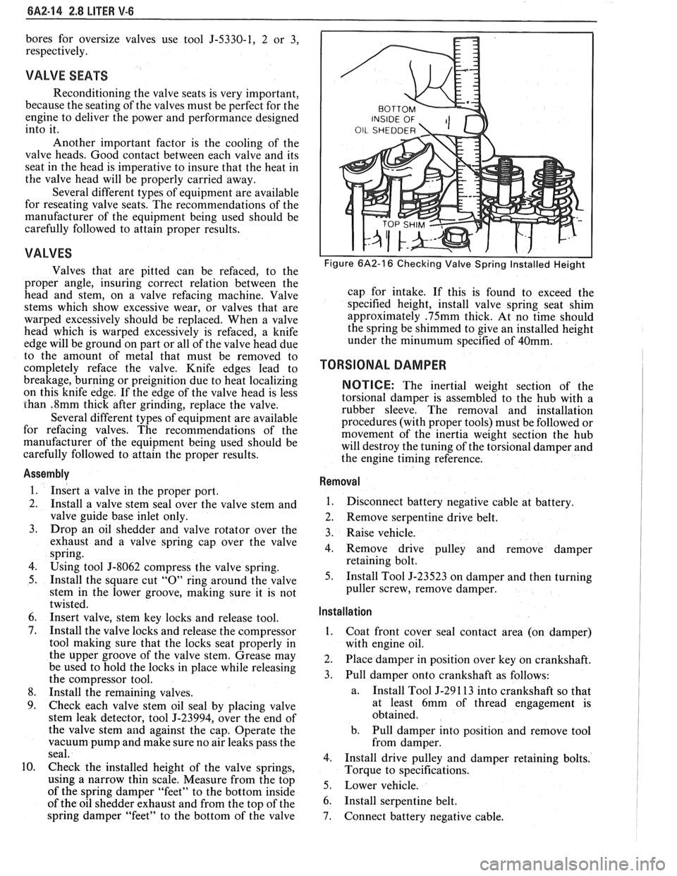
Check the installed height of the valve springs,
using
a narrow thin scale. Measure from the top
of the spring damper "feet" to the bottom inside
of the oil shedder exhaust and from the top of the
spring damper "feet" to the bottom of the valve
Figure 6A2-16 Checking Valve Spring Installed Height
cap for intake. If this is found to exceed the
specified height, install valve spring seat shim
approximately
.75mm thick. At no time should
the spring be shimmed to give an installed height
under the
minumum specified of 40mm.
TORSIONAL DAMPER
NOTICE: The inertial weight section of the
torsional damper is assembled to the hub with a
rubber sleeve. The removal and installation
procedures (with proper tools) must be followed or
movement of the inertia weight section the hub
will destroy the tuning of the torsional damper and
the engine timing reference.
Removal
1.
Disconnect battery negative cable at battery.
2. Remove serpentine drive belt.
3. Raise vehicle.
4. Remove drive pulley and remove damper
retaining bolt.
5. Install Tool J-23523 on damper and then turning
puller screw, remove damper.
Installation ,
1.
Coat front cover seal contact area (on damper)
with engine oil.
2. Place damper in position over key on crankshaft.
3. Pull damper onto crankshaft as follows:
a. Install
Tool J-29 1 13 into crankshaft so that
at least 6mm of thread engagement is
obtained.
b. Pull damper into position and remove tool
from damper.
4. Install drive pulley and damper retaining bolts.
Torque to specifications.
5. Lower vehicle.
6. Install serpentine belt.
7. Connect battery negative cable.
Page 385 of 1825
6A3-6 V-8 ENGINE
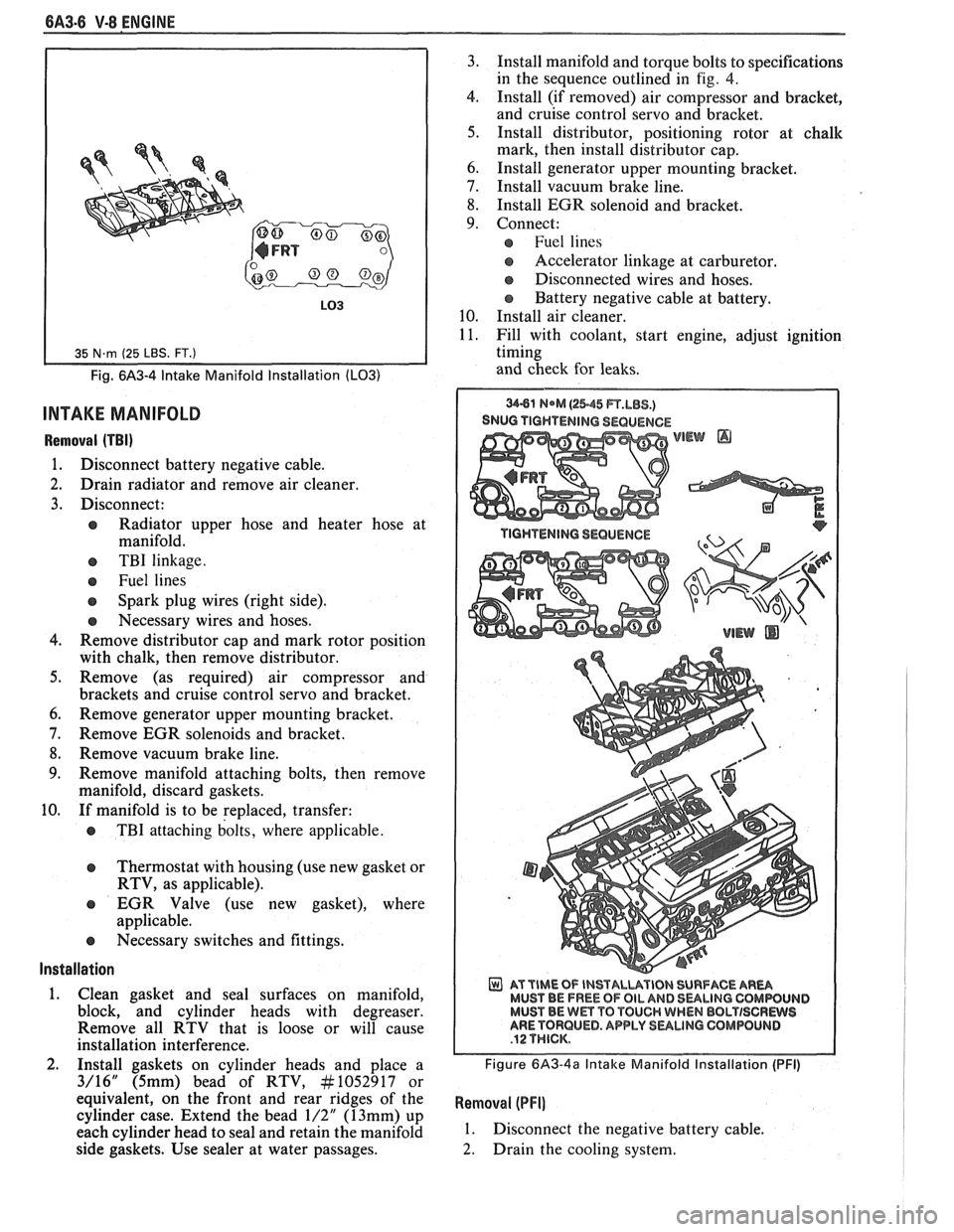
Fig. 6A3-4 Intake Manifold Installation (LO31
INTAKE MANIFOLD
Removal (TBI)
1. Disconnect battery negative cable.
2. Drain radiator and remove air cleaner.
3. Disconnect:
e Radiator upper hose and heater hose at
manifold.
e TBI linkage.
e Fuel lines
Spark plug wires (right side).
e Necessary wires and hoses.
4. Remove distributor cap and mark rotor position
with chalk, then remove distributor.
5. Remove (as required) air compressor and
brackets and cruise control servo and bracket.
6. Remove generator upper mounting bracket.
7. Remove EGR solenoids and bracket.
8. Remove vacuum brake line.
9. Remove manifold attaching bolts, then remove
manifold, discard gaskets.
10. If manifold is to be replaced, transfer:
e TBI attaching bolts, where applicable.
Thermostat with housing (use new gasket or
RTV, as applicable).
EGR Valve (use new gasket), where
applicable.
e Necessary switches and fittings.
lnstallation
1. Clean gasket and seal surfaces on manifold,
block, and cylinder heads with degreaser.
Remove all RTV that is loose or will cause
installation interference.
2. Install gaskets on cylinder heads and place a
3/16" (5mm) bead of RTV, At1052917 or
equivalent, on the front and rear ridges of the
cylinder case. Extend the bead
1/2" (13mm) up
each cylinder head to seal and retain the manifold
side gaskets. Use sealer at water passages. 3.
Install manifold and torque bolts to specifications
in the sequence outlined in
fig. 4.
4. Install (if removed) air compressor and bracket,
and cruise control servo and bracket.
5. Install distributor, positioning rotor at chalk
mark, then install distributor cap.
6. Install generator upper mounting bracket.
7. Install vacuum brake line.
8. Install EGR solenoid and bracket.
9. Connect:
Fuel lines
s Accelerator linkage at carburetor.
@ Disconnected wires and hoses.
Battery negative cable at battery.
10. Install air cleaner.
11. Fill with coolant, start engine, adjust ignition
timing
and check for leaks.
SNUG TIGHTENING SEQUENCE
WEW @
AT TIME OF INSTALUVIBN SURFACE AR- MUST BE FREE OF OIL AND 8ULlNG CQMWUIJD MUST BE Wm TO TOUCH WHEN BBLTISCRWS ARE TORQUED. APPLY SULINO GOMPOLINB
Figure 6A3-4a Intake Manifold Installation (PFI)
Removal (PFI]
1. Disconnect the negative battery cable.
2. Drain the cooling system.