1988 PONTIAC FIERO ignition
[x] Cancel search: ignitionPage 667 of 1825
6E3-A-14 2.8L (VIN S) DRIVEABILITY AND EMISSIONS
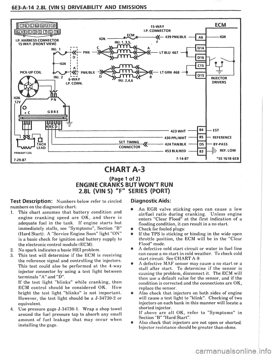
PICK-UP COIL
CHART A-3
(Page 1 of 2)
ENGINE CRANKS BUT WON'T RUN
2.8L (VIN S) ""F'" SERIES (PORT)
Test Description: Numbers below refer to circled
numbers on the diagnostic chart.
1. This chart
assunles that battery condition and
engine cranking speed are OK, and there is
adequate fuel in the tank. If engine starts but
immediately stalls, see "Symptoms", Section
"B"
(Hard Start). A "Service Engine Soon" light "ON"
is a basic check for ignition and battery supply to
the electronic control module
(ECM).
2. No sparlc indicates a basic HE1 problem.
3. This test will determine if the ECM is receiving
the reference signal and controlling the injectors.
This test could also be performed at the 4-way
injector connector by using a test light between
terminals
"A" and "D".
If the test light "blinks" while cranking, then
ECM control should be considered OK.
How
bright the test light "blinks" is not important.
However, the test light should be a
5-34730-2 or
equivalent.
4. Use pressure gage 5-34730-1. Wrap a shop towel
around the fuel pressure tap to absorb any small
amount of fuel leakage that may occur when
installing the gage.
Diagnostic Aids:
@ An EGR valve sticking open can cause a low
airlfuel ratio during cranking. Unless engine
enters "Clear Flood" at the first indication of a
flooding condition, it can result in a no start.
@ Check for fouled plugs:
@ If the TPS is sticking or binding in the wide open
throttle position, the ECM will be in the "Clear
Flood" mode.
@ A defective cold start circuit or water in fuel line
can cause a no start in cold weather.
To check cold
start circuit: See CHART
A-9.
e A defective MAF sensor may cause a no start or a
stall after start. 'I'o determine if the sensor is
causing the problem, disconnect it. The ECM will
then use a default value for the sensor, and if the
condition is corrected and the connections are OK,
replace the sensor.
@ Also check that injectors on both sides of engine
will cause a test light to "blink". Checking of two
injectors on each bank in this manner will locate a
shorted injector.
If
above are all OK, refer to "Symptoms" in
Section
"R" "Hard Start".
@ Also checlc that injectors are not open or shorted.
Injector resistance should be greater than ohms.
Page 669 of 1825
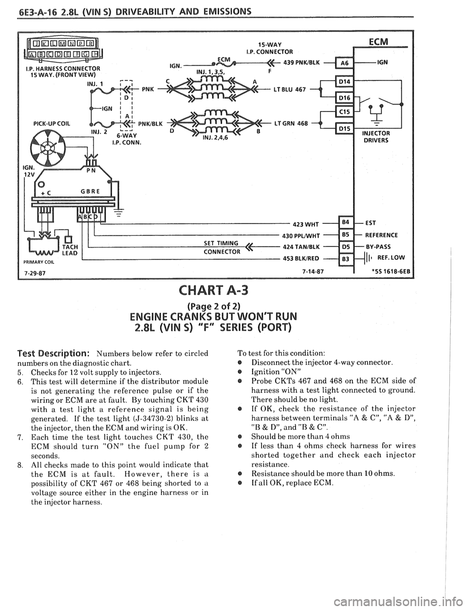
CHART A-3
(Page 2 of 2)
ENGINE CRANKS BUT WONT WN
2.8L (VIN S) ""FYSERIES (PORT)
Test Description: Numbers below refer to circled
numbers on the diagnostic chart.
5. Checks for 12 volt supply to injectors.
6. This
test will determine if the distributor module
is not generating the reference pulse or if the
wiring or ECM are at fault. By touching CKT 430
with a test light a reference signal is being
generated. If the test light
(5-34730-2) blinks at
the injector, then the ECM and wiring is OK.
7. Each time
the test light touches CKT 430, the
ECM should turn "ON" the fuel
punlp for 2
seconds.
8. All
checks made to this point would indicate that
the ECM is at fault. However, there is
a
possibility of CKT 467 or 468 being shorted to a
voltage source either in the engine harness or in
the injector harness. To
test for this condition:
@ Disconnect the injector 4-way connector.
@ Ignition "ON"
Probe
CKTs 467 and 468 on the ECM side of
harness with a test light connected to ground.
There should be no light.
@ If OK, check the resistance of the injector
harness between terminals
"A & C", "A & D",
"B & D", and .'B & C".
@ Should be more than 4 ohms
@ If less than 4 ohms check harness for wires
shorted together and check each injector
resistance.
@ Resistance should be more than 10 ohms.
@ If all OK, replace ECM.
Page 671 of 1825
6E3-A-I8 2.8b (VIN 5) DRIVEABILITY AND EMISSIONS
PUMP INLET FILTER
IN-TANK PUMP
FUEL
PRESSURE CONNECTOR
CHART A-7
(Page 4 of 2)
FUEL SYSTEM DsAGNOSBS
2.8L (VIN S) ""FYSERBES (PORT)
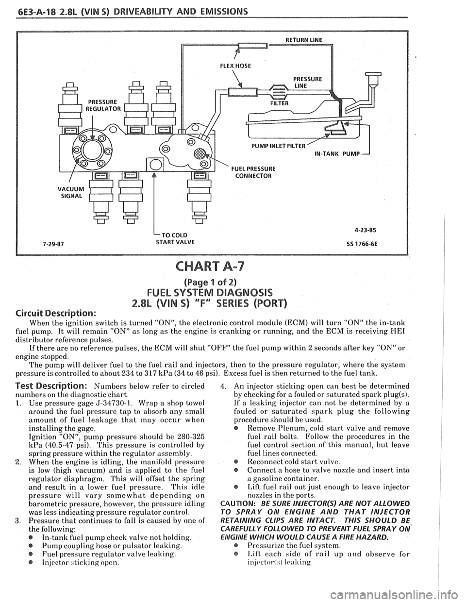
Circuit Description:
When the ignition switch is turned "ON", the electronic control module (ECM) will turn "ON" the in-tank
fuel pump. It will remain "ON" as long as the engine is cranking or running, and the ECM is receiving
HE1
distributor reference pulses.
If there are no reference pulses, the ECM will shut "OFF" the fuel pump within
2 seconds after key "ON" or
engine stopped.
The pump will deliver fuel to the fuel rail and injectors, then to the pressure regulator, where the system
pressure is controlled to about 234 to 317
kPa (34 to 46 psi). Excess fuel is then returned to the fuel tank.
Test Description: Numbers below refer to circled
numbers on the diagnostic chart.
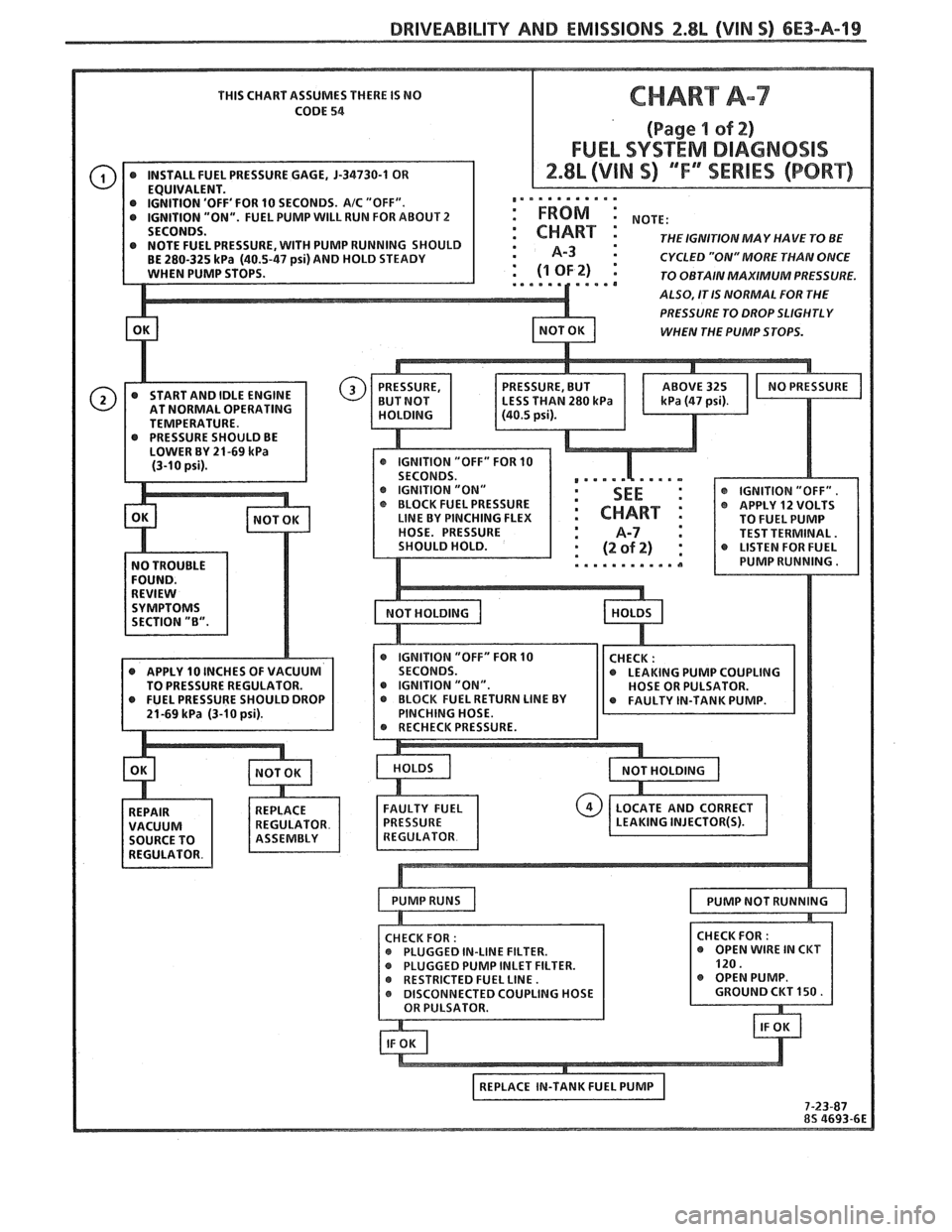
1. Use pressure gage 5-34730-1. Wrap a shop towel
around the fuel pressure tap to absorb any small
amount of fuel leakage that
may occur when
installing the gage.
Ignition "ON", pump pressure should be 280-325
kPa (40.5-47 psi). This pressure is controlled by
spring pressure within the regulator assembly.
2. When the engine is idling, the manifold pressure
is low (high vacuum) and is applied to the fuel
regulator diaphragm. This will offset the spring
and result in a lower fuel pressure.
'This idle
pressure will vary somewhat depending on
barometric pressure, however, the pressure idling
was less indicating pressure regulator control.
3. Pressure that continues to fall is caused by one of
the following:
In-tank fuel pump check valve not holding.
@ Pump coupling hose or pulsator leaking.
Fuel pressure regulator valve leaking.
@ Injector sticking open. 4.
An injector sticking open can best be determined
by checking for a fouled or saturated spark
plug(s).
If a leaking injector can not be determined by a
fouled or saturated spark plug the following
procedure should be used.
e Remove Plenum, cold start valve and remove
fuel rail bolts. Follow the procedures in the
fuel control section of this manual, but leave
fuel lines connected.
@ Reconnect cold start valve.
@ Connect a hose to valve nozzle and insert into
a gasoline container.
@ Lift fuel rail out just enough to leave injector
nozzles in the ports.
CAUTION: BE SURE INJEePOR(S) ARE NOT ALLOWED
PO SPRAY ON ENGINE AND THAT INJECTOR
RETAINING
CLIPS ARE INTACT. PHIS SHOULD BE
CAREFULLY
FOLLOWD PO PREVENT FUEL SPRAY ON'
ElZIGlNE WHICH WOULD CAUSE A FIRE HAZARD.
@ Pressurize the fuel system.
@ I.if't each side of rail up and observe for
injc~ctot-l.) It.ulting
Page 672 of 1825
DRIVEABILITY AND EMISSIONS 2.8L (VIN S) 6E3-A-19
THIS CHART ASSUMES THERE IS NO
CODE
54
'OFF' FOR 10 SECONDS. AIC "OFF". ,,. . . . . . . . .'.
"ON". FUEL PUMP WILL RUN FOR ABOUT 2 : FROM :
THE IGNITIONMAY HAVE TO BE : A-3 : CYCLED "ON" MORE THAN ONCE
TO OBTAIN MAXIMUM PRESSURE.
ALSO, IT IS NORMAL FOR THE
PRESSURE TO DROP SLIGHTLY
WHEN THE PUMP STOPS.
AT NORMAL OPERATING
TEMPERATURE.
IGNITION "ON"
@ IGNITION "OFF".
BLOCK FUEL PRESSURE @ APPLY 12 VOLTS LINE BY PINCHING FLEX
TO FUEL PUMP
HOSE. PRESSURE TEST TERMINAL.
@ IGNITION "OFF" FOR 10 @ APPLY 10 INCHES OF VACUUM
LEAKING PUMP COUPLING
TO PRESSURE REGULATOR. @ IGNITION "ON".
INLET FILTER.
Page 683 of 1825
6E3-A-38 2.8b (VIM S) DRIVEABILITY AND EMISSIONS
FRONT VIEW OF CONNECTOR
MODE SIGNAL
5V REFERENCE
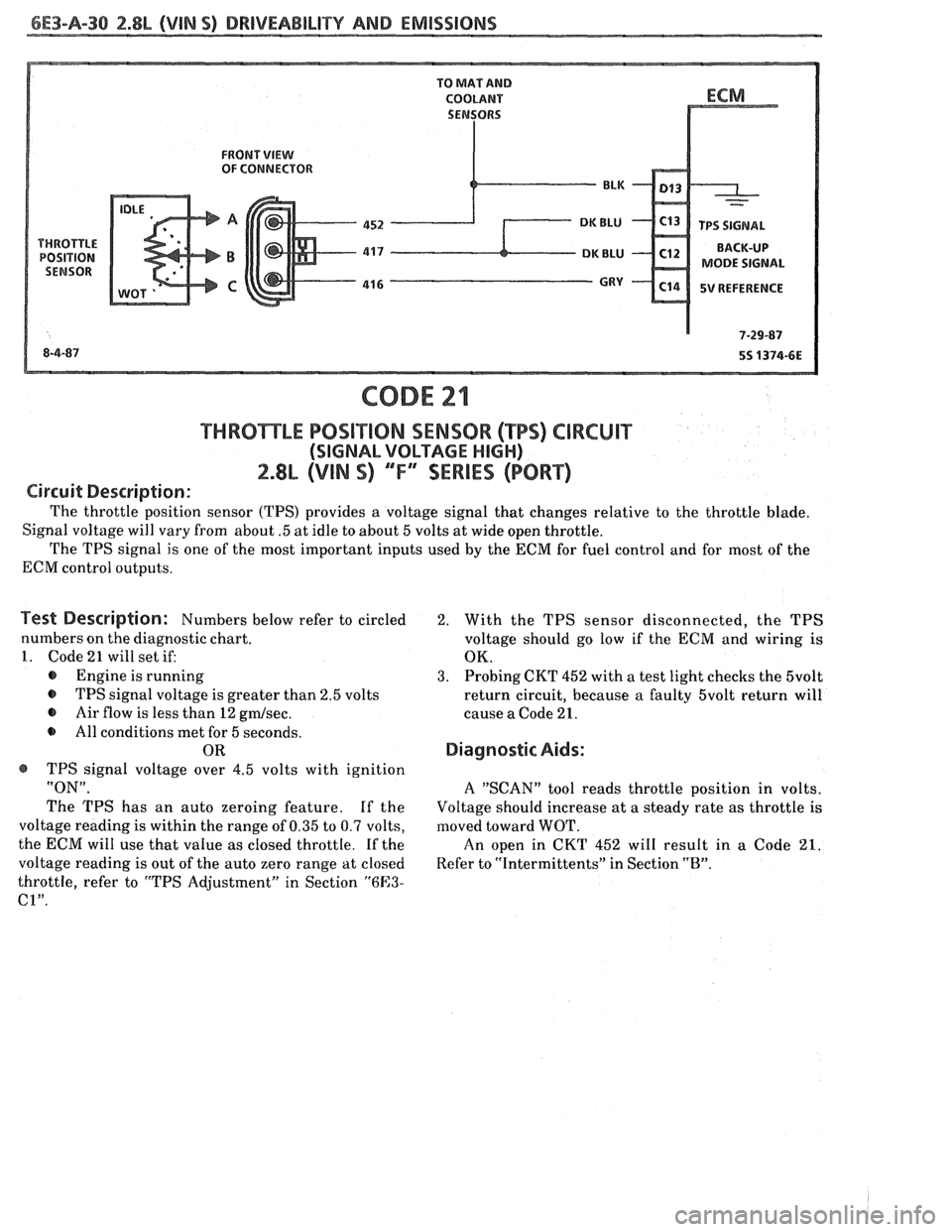
THRBmLE POSiT10N SENSOR (TPS) CIRCUIT
(SIGNAL VOLTAGE HIGH)
2.8L (VIN S) ""F-SERIES (PORT)
Circuit Description:
The throttle position sensor (TPS) provides a voltage signal that changes relative to the throttle blade.
Signal voltage will vary from about
.5 at idle to about 5 volts at wide open throttle.
The TPS signal is one of the most important inputs used by the ECM for fuel control and for most of the
ECM control outputs.
Test Description: Numbers below refer to circled
numbers on the diagnostic chart.
1. Code 21 will set if:
@ Engine is running
@ TPS signal voltage is greater than 2.5 volts
@ Air flow is less than 12 gmlsec.
All conditions met for 5 seconds.
OR
@ TPS signal voltage over 4.5 volts with ignition
"ON".
The TPS has an auto zeroing feature. If the
voltage reading is within the range of 0.35 to 0.7 volts,
the ECM will use that value as closed throttle.
If the
voltage reading is out of the auto zero range at closed
throttle, refer to "TPS Adjustment" in Section
"6E3-
C1".
2. With the TPS sensor disconnected, the TPS
voltage should go low if the
ECM and wiring is
OK.
3. Probing CKT 452 with a test light checks the 5volt
return circuit, because a faulty 5volt return will
cause a Code 21.
Diagnostic Aids:
A "SCAN" tool reads throttle position in volts.
Voltage should increase at a steady rate as throttle
is
moved toward WOT.
An open in CKT 452 will result in a Code 21.
Refer to "Intermittents" in Section "B".
Page 690 of 1825
DRIVEABILITY AND EMISSIONS 2.8L (VIN O) 6E3-A-37
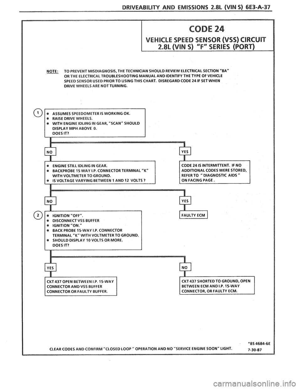
NOTE: TO
PREVENT MISDIAGNOSIS, THE TECHNICIAN SHOULD REVIEW ELECTRICAL SECTION "8A"
OR THE ELECTRICAL TROUBLESHOOTING MANUAL AND IDENTIFY THE TYPE OF VEHICLE
SPEED SENSOR USED PRIOR TO USING
THIS CHART. DISREGARD CODE 24 IF SET WHEN
DRIVE
WHEELS ARE MOT TURNING.
IN GEAR, "SCAN" SHOULD
CTOR TERMINAL
"K"
IGNITION "ON."
BACK PROBE 15-WAY I.P. CONNECTOR
SHOULD DISPLAY
10 VOLTS OR MORE.
Page 693 of 1825
6E3-A-40 2.8L (VIN 5) DRIVEABILITY AND EMISSIONS
VENT FILTER
450 BLWHT ITCH SIGNAL -
CODE 32
EGR SYSTEM FAILURE
2.8L (VIN S) "F" "SERIES (PORT)
Circuit Description:
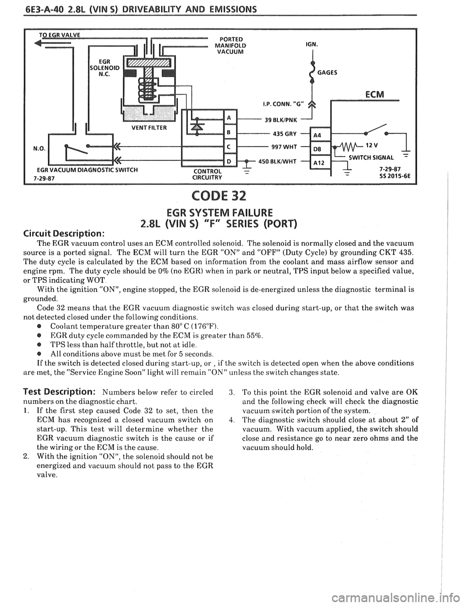
The EGR vacuum control uses an ECM controlled solenoid. The solenoid is normally closed and the vacuum
source is a ported signal. The ECM will turn the EGR "ON" and "OFF" (Duty Cycle) by grounding CKT
435.
The duty cycle is calculated by the ECM based on information from the coolant and mass airflow sensor and
engine rpm. The duty cycle should be
0% (no EGR) when in park or neutral, TPS input below a specified value,
or TPS indicating WOT
With the ignition
"ON", engine stopped, the EGR solenoid is de-energized unless the diagnostic terminal is
grounded. Code 32 means that the EGR vacuum diagnostic switch was closed during start-up, or that the switch was
not detected closed under the following conditions.
@ Coolant temperature greater than 80" C (176°F).
@ EGR duty cycle commanded by the ECM is greater than 55%.
@ TPS less than half throttle, but not at idle.
@ All conditions above must be met for 5 seconds.
If the switch is detected closed during start-up, or
, if the switch is detected open when the above conditions
are met, the "Service Engine Soon" light will remain "ON" unless the switch changes state.
Test Description: Numbers below refer to circled 3. 'Po this point the EGR solenoid and valve are OK
numbers on the diagnostic chart. and the following check will check the diagnostic
1. If the first step caused Code 32 to set, then the vacuutn switch portion of the system.
ECM has recognized a closed vacuum switch on
4. The diagnostic switch should close at about 2" of
start-up. This test will determine whether the
vacuum. With vacuum applied, the switch should
EGR vacuum diagnostic switch is the cause or if close and resistance go to near zero ohms and the
the wiring or the ECM is the cause. vacuum should hold.
2. With the ignition "ON", the solenoid should not be
energized and vacuum should not pass to the EGR
valve.
Page 695 of 1825
6E3-A-42 2.8L (VIN S) DRIVEABILITY AND EMISSIONS
MAF SENSOR CONNECTOR
MAF SENSOR
940
ORNIBLK BRNMIHT 528
450 BLWHT
MAF RELAY
CODE 33
MASS AIR FLOW (MAF) SENSOR CIRCUIT
(GMISEC HIGH)
2.8L (VIN S) ""FXERIES (PORT)
Circuit Description:
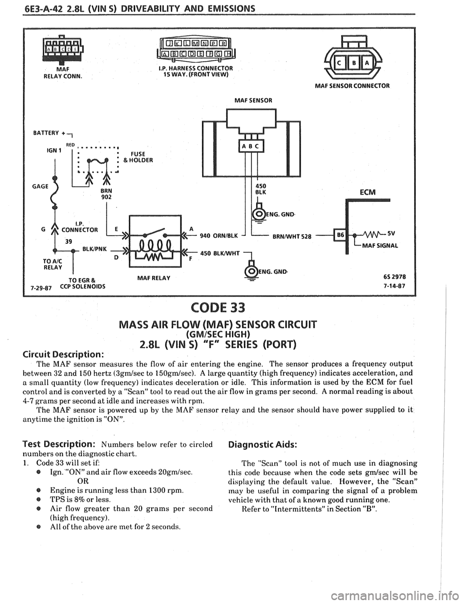
The MAF sensor measures the flow of air entering the engine. The sensor produces a frequency output
between 32 and 150 hertz
(3gdsec to 150gmlsec). A large quantity (high frequency) indicates acceleration, and
a small quantity (low frequency) indicates deceleration or idle. This information is used by the
ECM for fuel
control and is converted by a "Scan" tool to read out the air flow in grams per second.
A normal reading is about
4-7 grams per second at idle and increases with rpm.
The MAF sensor is powered up by the MAF sensor relay and the sensor should have power supplied to it
anytime the ignition is "ON".
Test Description: Numbers below refer to circled Diagnostic Aids:
numbers on the diagnostic chart.
1. Code 33 will set if:
The "Scan" tool is not of much use in diagnosing
@ Ign. "ON" and air flow exceeds 20gdsec. this code because when the code sets gmlsec will be
OR displaying the default value. However, the "Scan"
@ Engine is running less than 1300 rpm. may be useful in comparing the signal of a problem
@ TPS is 8% or less.
vehicle with that of a known good running one.
@ Air flow greater than 20 grams per second Refer to "Intermittents" in Section "B".
(high frequency).
(9 All of the above are met for 2 seconds.