1988 PONTIAC FIERO ignition
[x] Cancel search: ignitionPage 601 of 1825
6E2-C4-2 5.8L (VIN E) DRIVEABILIW AND EMISSIONS
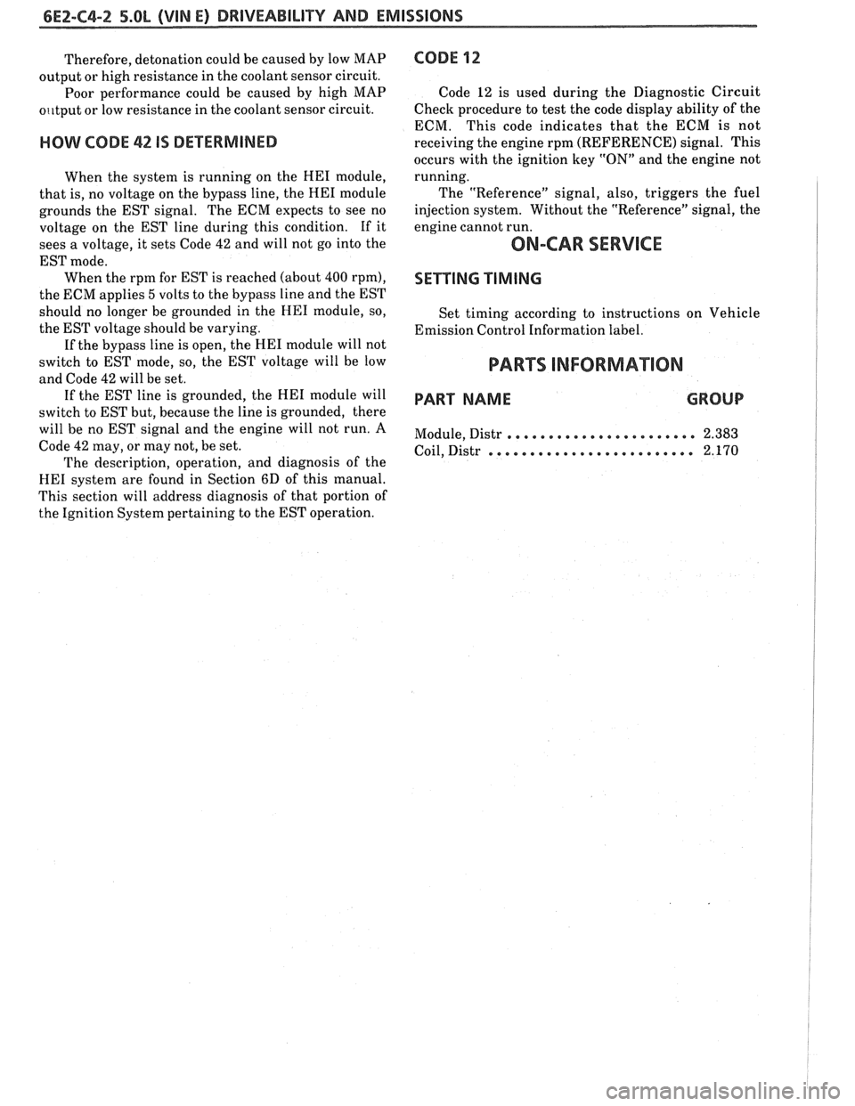
Therefore, detonation could be caused by low MAP
output or high resistance in the coolant sensor circuit.
Poor performance could be caused by high MAP
o~~tput or low resistance in the coolant sensor circuit.
HOW CODE 42 IS DETERMINED
When the system is running on the HE1 module,
that is, no voltage on the bypass line, the
HE1 module
grounds the EST signal. The ECM expects to see no
voltage on the EST line during this condition. If it
sees a voltage, it sets Code
42 and will not go into the
EST mode. When the rpm for EST is reached (about
400 rpm),
the ECM applies 5 volts to the bypass line and the EST
should no longer be grounded in the
HE1 module, so,
the EST voltage should be varying.
If the bypass line is open, the
HE1 module will not
switch to EST mode, so, the EST voltage will be low
and Code
42 will be set.
If the EST line is grounded, the HE1 module will
switch to EST but, because the line is grounded, there
will be no EST signal and the engine will not run. A
Code
42 may, or may not, be set.
The description, operation, and diagnosis of the
HE1 system are found in Section 6D of this manual.
This section will address diagnosis of that portion of
the Ignition System pertaining to the EST operation.
CODE 12
Code 12 is used during the Diagnostic Circuit
Check procedure to test the code display ability of the
ECM. This code indicates that the ECM is not
receiving the engine rpm (REFERENCE) signal. This
occurs with the ignition key
"ON" and the engine not
running.
The "Reference" signal, also, triggers the fuel
injection system. Without the "Reference" signal, the
engine cannot run.
ON-CAR SERVICE
SETTING TIMING
Set timing according to instructions on Vehicle
Emission Control Information label.
PARTS INFORMATION
PART NAME GROUP
....................... Module, Distr 2.383
......................... Coil, Distr 2.170
Page 603 of 1825
6E2-C4-4 5.OL (VIN E) DRIVEABILITY AND EMISSIONS
CONNECTOR
430 PPUWHf
424 TANIBLK
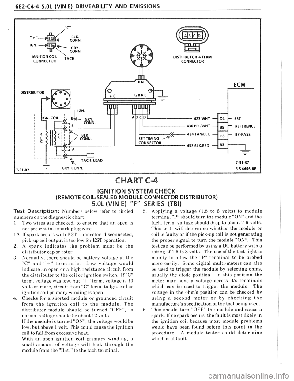
CHART C-4
IGMB"$IIQN SYSTEM CHECK
(REMOTE COILSEALED MODULE CONNECTOR DISTRIBUTOR)
5.OL (VIN E) 'TF"7SEWBES (TBi)
Test De~driptian: Siin~bers below refer to circled
numbers
on the diagilostic chart.
1. 'Two wires are checkecl, to ensure that ti11 open is
not present
in a spark plug wire.
IA. If spark occurs with EST connector disconnected,
pick-LIP coil
oiltp~it is too !OW for l,:SrI' operation.
2. A spark indicates t,he problem must be the
distributor cap or rotor.
3. Normally, there should be battery voltage at the "c" ailti " -I-" terminals. Low voltage would
indicate an open or
a high resistance circuit from
the distributor to the coil or ignition switch. If "C"
term. voltage was low, but
"+" term. voltage is 10
volts or more, circuit
from "C" term. to Ign. coil or
ignition coil
primary winding is open.
4. Checks for a shorted module or grounded circuit
from the ignition coil to the module.
'I'hc
distributor module should be turned "OFF", so
normal voltage should be
about 12 volts.
If the module is turned "ON", the voltage would be
low, but above
1 volt. This could cause the ignition
coil to fail from excessive heat.
With an open ignition coil primary winding,
a
small amount of voltage will leak throtrgh the
module from the "Bat." to the tach terminal.
5. Applying a voltage (1.5 to 8 volts) to module
terminal
"P" should turn the module "ON" and the
tach. term. voltage should drop to about 7-9 volts.
'I'his test will determine whether the module or
coil is faulty or if the pick-up coil is not generating
the proper signal to turn the module "ON". This
test can be performed by using a DC battery with a
rating of 1.5 to
8 volts. The use of the test light is
~nainly to tillow the "P" terminal to be probed
tilore easily. Some digital multi-meters can also
be used to trigger the
module by selecting ohms,
i~sually the diode position. 111 this position the
meter may have a voltage across it's terminals
which can be
used to trigger the module. The
voltage in the ohm's position can be checked
by
using a second meter or by checking the
manufacture's specification of the tool being used.
6. 'I'his should turn "OFF" the module and cause a
spark. If no spark occurs, the fault is most likely in
the ignition coil because
most module problems
would have been found before this point in the
procedure.
A modulc tester could determine
which is at fault.
Page 627 of 1825
6Ef-C8-2 BRlVEABlLlYV AND EMISSIONS - 5.OL (VIN E) ----
RESULTS OF INCORRECTTCC OPERATION
An engine stall will result if the converter clutch
remains applied at all times.
If the converter clutch does not apply, fuel
economy may be lower than expected.
The transmission converter clutch
(TCC) system
has different operating characteristics than an
automatic transmission without TCC.
If the driver
complains of a "chuggle" or "surge" condition, the car
should be road tested and compared to a similar car to
see if a real problem exists. Another TCC complaint
may be
a downshift felt when going up a grade,
especially with cruise control. This may not be
a
downshift, but a clutch disengagement due to the
change in TPS to maintain cruising speed. The
Owner's Manual section on TCC operation should be
reviewed with the driver.
DIAGNOSIS
The diagnosis of the TCC system is covered in
ClIART C-8. If the ECM detects a problem in the VSS
system, a Code
24 should set. In this case see Code 24
Chart.
If the ECM doesn't switch the TCC "ON" when
driving, but will turn it
"ON" when the "test"
terminal is grounded with ignition "ON" and engine
stopped, the sensors such as coolant, speed, and
throttle position should be checked.
ON-CAW SERVICE
@ See Section "7" for TCC Solenoid.
@ See Section "SH" for VSS (HP mounted) and brake
system.
PAR- SNFORMATBIQN
PART NAME GRQUQ
.......................... Sensor, VSS 9.761
........................ Solenoid, TCC 4.122
Page 629 of 1825

6EZ-C8-4 DRIVEABILITY AND EMISSIONS - 5.OL (VIN E)
I5 WAY (FRONT VIEW)
SPEED INPUT
4rH GEAR SIGNAL
422 TANIBLK
ALDL CONNECTOR
CHART C-8A
TRANSMISSION CONVERTER CLUTCH (TCC)
ELECTRICAL DIAGNOSIS
(Page 1 of 2)
5.OL (VIN E) "F" "SERIES (TBI)
Circuit Description:
The purpose of the automatic transmission torque converter clutch is to eliminate the power loss of the
torque converter, when the vehicle is in a cruise condition. This allows the convenience of the automatic
transmission and the fuel economy of a manual transmission.
Fused battery ignition is supplied to the TCC solenoid through the brake switch. the ECM will engage
TCC
by grounding CKT 422 to energize the solenoid.
TCC will engage when:
- Vehicle speed above 24 mph - Engine at normal operating temperature (above 70°C, 156°F)
- Throttle position sensor output not changing, indicating a steady road speed
- Brake switch closed
Test Description: Numbers below refer to circled solenoids
and relays before installing a
numbers on the diagnostic chart. replacement ECM. Replace
any solenoid or relay
1. Confirms 12 volt supply as well as continuity of that
measures less than 20 ohms.
TCC circuit.
2. Grounding the diagnostic terminal with engine Diagnostic Aids:
"OFF", should energize the capability of the ECM An
engine coolant thermostat that is stuck open or
to control the solenoid. opens
at too low a temperature, may result in an
3. Solenoid coil resistance must measure more than inoperative TCC.
20 ohms. Less resistance will cause early failure
of the ECM
drive^.". Using an ohmmeter, check
the solenoid coil resistance of
all ECM controlled
Page 634 of 1825
DRIVEABILITY AND EMISSIONS - S.OL (WIN E) 6EZ-CS-9
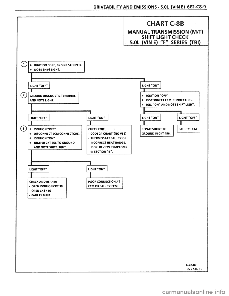
CHART C-8B
MANUAL TRANSMISSION (Mn)
SHIFT LIGHT CHECK
CM CONNECTORS.
IGNITION "ON" THERMOSTAT FAULTY OR
JUMPER CKT 456 TO GROUND INCORRECT HEAT RANGE.
IF OK, REVIEW SYMPTOMS
CHECK AND REPAIR:
- OPEN IGNITION CKT 39
- OPEN CKT 456
Page 642 of 1825
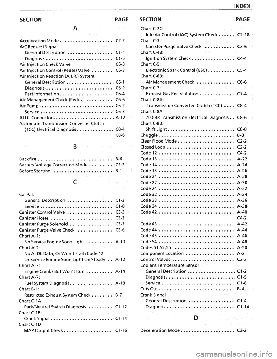
SECTION PAGE
A
Acceleration Mode .................... C2-2
AIC Request Signal
General Description
................. C1-4
Diagnosis ......................... C1-5
Air Injection Check Valve C6-3
Air Injection Control (Pedes) Valve
........ C6-3
Air
lnjection Reaction (A.I.R.) System
General Description
.................. C6- 1
Diagnosis ......................... C6-2
Part Information
.................... C6-4
Air Management Check (Pedes)
.......... C6-6
Air Pump
............................ C6-2
........................... Service C6-3
ALDL Connector ....................... A-1 2
Automatic Transmission Converter Clutch
(TCC) Electrical Diagnosis
.............. C8-4
C8-6
B
Backfire ............................ 6-6
......... Battery Voltage Correction Mode C2-2
Before
Start~ng ...................... B-1
C
Cal Pak General
Descript~on ................. C1-2
Service
........................... C1-8
Canister Control Valve
................. C3-2
Canister Hoses
....................... C3-3
Canister Purge Solenoid
................ C3-3
Canister Purge Valve Check
............. C3-6
Chart A-
I :
No Service Engine Soon Light .......... A-10
Chart A-2:
No ALDL Data. Or Won't Flash Code 12.
Or Service Engine Soon Light On Steady
. . A-1 2
Chart A-3:
Engine Cranks But Won't Run
.......... A-14
Chart A-7:
Fuel System Diagnosis
................ A-1 8
Chart
B-1:
Restricted Exhaust System Check ........ 6-7
Chart C-IA:
ParkINeutral Switch Diagnosis ......... Cl-12
Chart C-16:
Crank Signal
....................... C1-14
Chart C-1 D
.................. MAP Output Check C1-16
SECTION
Chart C-2C:
Idle Air Control (IAC) System Check ...... C2-18
Chart C-3:
Canister Purge Valve Check
........... C3-6
Chart C-4B:
Ignition System Check
................ C4-4
Chart C-5:
Electronic Spark Control
(ESC) .......... C5-4
Chart C-66:
Air Management Check
.............. C6-6
Chart C-7:
Exhaust Gas Recirculation
............. C7-4
Chart
C-$A:
Transmission Converter Clutch (TCC) .... C8-4
Chart
C-8A
700-4R Transmission Electrical Diagnosis . . C8-6
Chart
C-86:
Shift Light ......................... C8-8
Chuggle
............................ B-3
Clear Flood Mode
..................... C2-2
Closed Loop
......................... C2-2
Code12
............................ C4-2
Code13
............................ A-22
Code14
............................ A-24
Code43
............................ A-42
Code44
............................ A-44
Code45
............................ A-46
Code54
............................ A-48
Codes 5 1.52. 55
...................... A-50
Component Location
.................. A-2
Control Valves
....................... C3-3
Coolant Temperature Sensor
General Description
.................. C1-2
Diagnosis
.......................... Cl-5
Service
........................... C1-8
Cuts Out ............................ 6-4
Crank Signal General Description
................. C1-4
Diagnosis
......................... C1-14
D
Deceleration Mode .................... C2-2
Page 643 of 1825
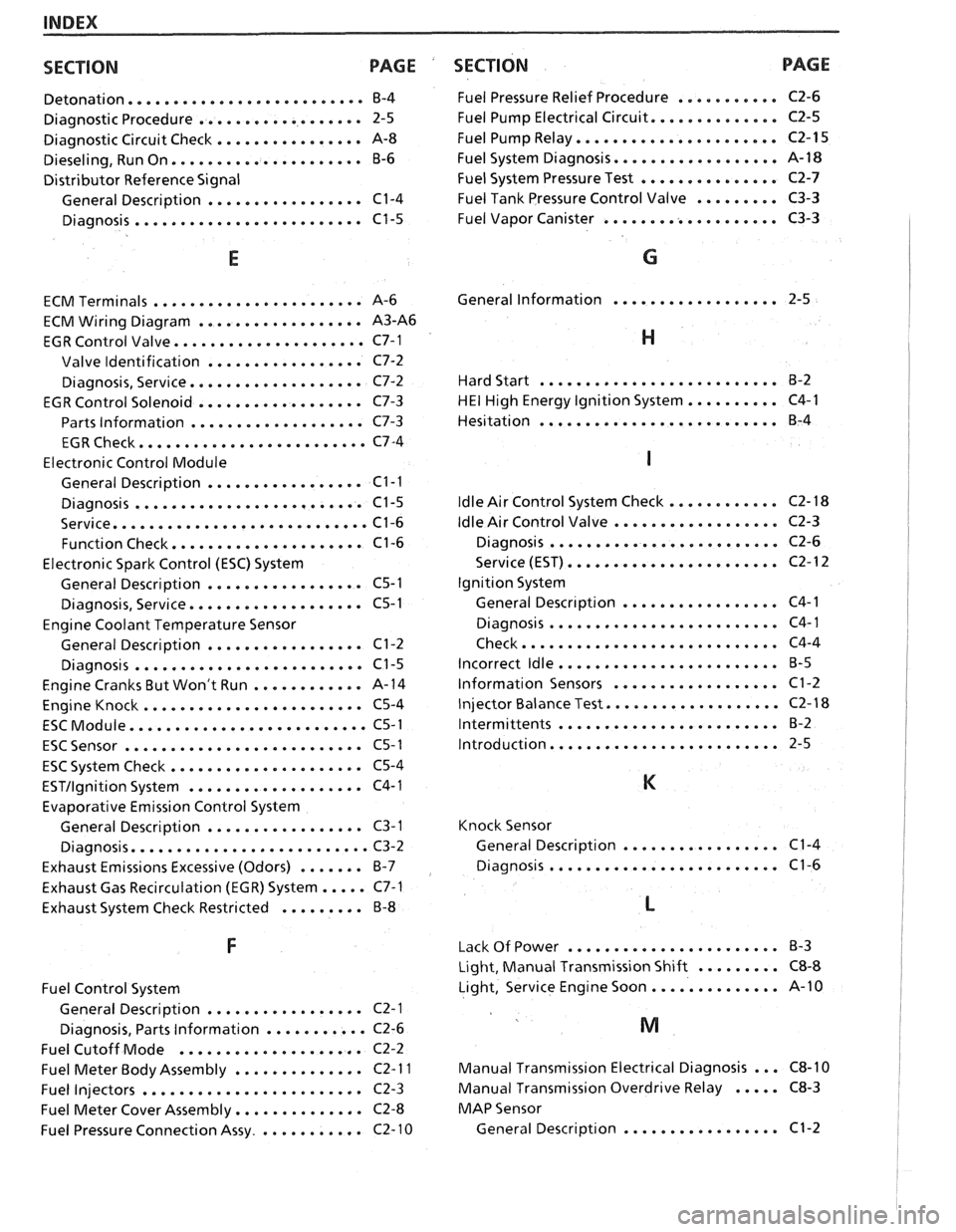
INDEX
SECTION PACE
....................... Detonation... B-4
.................. Diagnostic Procedure 2-5
................ Diagnostic Circuit Check A-8
..................... Dieseling. Run On B-6
Distributor Reference Signal
................. General Description C1-4
......................... Diagnosis C1-5
E
.................... ECM Terminals ... A-6
.................. ECM Wiring Diagram A3-A6
..................... EGR Control Valve C7-1
................. Valve Identification C7-2
................... Diagnosis. Service C7-2
EGR Control Solenoid
.................. C7-3
Parts Information
................... C7-3
......................... EGR Check C7-4
Electronic Control Module
................. General Description C1-I
......................... Diagnosis C1-5
............................ Service C1-6
..................... Function Check C1-6
Electronic Spark Control (ESC) System
................. General Description C5-1
................... Diagnosis. Service C5-I
Engine Coolant Temperature Sensor
................. General Description C1-2
......................... Diagnosis C1-5
Engine Cranks But Won't Run
............ A-14
........................ Engine Knock C5-4
.......................... ESC Module C5-1
.......................... ESC Sensor C5-1
..................... ESC System Check C5-4
ESTIlgnition System ................... C4-1
Evaporative Emission
Conirol System
General Description
................. C3-1
.......................... Diagnosis C3-2
Exhaust Emissions Excessive (Odors)
....... B-7
Exhaust Gas Recirculation (EGR) System
..... C7-1
Exhaust System Check Restricted
......... B-8
Fuel Control System
General Description
................. C2-1
Diagnosis. Parts Information
........... C2-6
Fuel Cutoff Mode
.................... C2-2
Fuel Meter Body Assembly
.............. C2- 1 I
Fuel Injectors ........................ C2-3
Fuel Meter Cover Assembly
.............. C2-8
Fuel Pressure Connection Assy
............ C2- 10
SECTION PAGE
........... Fuel Pressure Relief Procedure C2-6
.............. Fuel Pump Electrical Circuit C2-5
...................... Fuel Pump Relay C2-15
.................. Fuel System Diagnosis A- 18
............... Fuel System Pressure Test C2-7
......... Fuel Tank Pressure Control Valve C3-3
................... Fuel
Vapor Canister C3-3
G
.................. General Information 2-5
H
.......................... Hard Start B-2
.......... HE1 High Energy Ignition System C4-1
.......................... Hesitation
B-4
............ ldle Air Control System Check
.................. ldle Air Control Valve
......................... Diagnosis
....................... Service (EST)
Ignition System
................. General Descr~ption
......................... Diagnosis
Check
............................
........................ Incorrect ldle
.................. lnformation Sensors
................... Injector Balance Test
........................ Intermittents
......................... Introduction
Knock Sensor
................. General Description C1-4
......................... Diagnosis C1-6
....................... Lack Of Power B-3
Light. Manual Transmission Shift
......... C8-8
Light. Service Engine Soon
.............. A-10
Manual Transmission Electrical Diagnosis
... C8-10
Manual Transmission Overdrive Relay ..... C8-3
MAP Sensor
General Description
................. C1-2
Page 647 of 1825
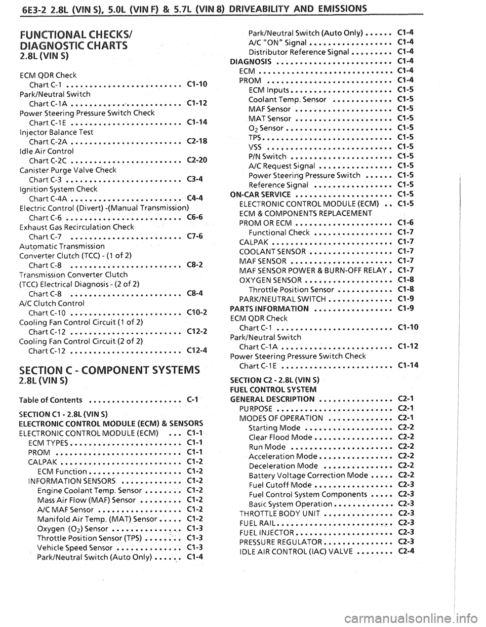
FUNCTIONAL CHECKS/
DIAGNOSTIC CHARTS
2.8L (VIN S)
ECM QDR Check
......................... Chart C-1 C1-10
ParkINeutral Switch
......................... Chart C-1A C1-12
Power Steering Pressure Switch Check
........................ ChartC-1E C1-14
Injector Balance Test
........................ Chart C-2A C2-18
Idle Air Control
........................ Chart C-2C C2-20
Canister Purge Valve Check
......................... Chart C-3 C3-4
Ignition System Check
........................ Chart C-4A C4-4
Electr~c Control (Divert) -(Manual Transmission)
......................... Chart C-6 C6-6
Exhaust Gas Recirculation Check
........................ Chart C-7 C7-6
Automatic Transmission
Converter Clutch (TCC)
. (I of 2)
........................ Chart C-8 C8-2
Transmiss~on Converter Clutch
(TCC) Electrical Diagnosis
. (2 of 2)
........................ Chart C-8 C8-4
A/C Clutch Control
........................ Chart C-10 C10-2
Cooling Fan Control Circuit (I of 2)
........................ Chart C-12 C12-2
Cooling Fan Control Circuit (2 of 2)
........................ Chart C-12 C12-4
ParklNeutral Switch (Auto Only) ...... C1-4
AIC "ON" Signal .................. C1-4
Distributor Reference Signal ......... C1-4
......................... DIAGNOSIS C1-4
............................. ECM C1-4
........................... PROM C1-4
...................... ECM Inputs C1-5
Coolant Temp . Sensor ............. C1-5
..................... MAFSensor C1-5
..................... MAT Sensor C1-5
....................... 02Sensor C1-5
TPS ............................ C1-5
........................... VSS C1-5
...................... PIN Switch C1-5
................ A/C Request Signal C1-5
Power Steering Pressure Switch ...... C1-5
................. Reference Signal C1-5
ON-CAR SERVICE ..................... C1-5
ELECTRONIC CONTROL MODULE (ECM) . . C1-5
ECM & COMPONENTS REPLACEMENT
..................... PROM OR ECM C1-6
................. Functional Check C1-7
CALPAK .......................... C1-7
COOLANT SENSOR .................. C1-7
MAFSENSOR ...................... C1-7
MAF SENSOR POWER & BURN-OFF RELAY . C1-7
................... OXYGEN SENSOR C1-8
Throttle Position Sensor ............ C1-8
PARKINEUTRALSWITCH .............. C1-9
................. PARTS INFORMATION C1-9
ECM QDR Check
................... ... Chart C-1 ... C1-10
ParktNeutral Switch
........................ ChartC-1A C1-12
Power Steering Pressure Switch Check
........................ SECTION C . COMPONENT SYSTEMS ChartC-lE C1-14
2.8L (VIN S) SECTION C2 . 2.8L (WIN S)
FUEL CONTROL SYSTEM
................ 'Table of Contents .................... C-1 GENERAL DESCRIPTION C2-1
SECTION
C1 . 2.8L (VIN S)
ELECTRONIC CONTROL MODULE (ECM)
& SENSORS
ELECTRONIC CONTROL MODULE (ECM) ... C1-1
........................ ECM TYPES C1-1
........................... PROM C1-1
CALPAK .......................... C1-2
.................... ECM Function C1-2
............. INFORMATION SENSORS C1-2
Engine Coolant Temp . Sensor ........ C1-2
Mass Air Flow (MAF) Sensor ......... C1-2
.................. A/C MAF Sensor Cl-2
Manifold Air Temp . (MAT) Sensor ..... C1-2
Oxygen (Oz)Sensor ............... C1-3
Throttle Position Sensor (TPS) ........ C1-3
Vehicle Speed Sensor .............. C1-3
ParkINeutral Switch (Auto Only) ...... C1-4
......................... PURPOSE C2-1
.............. MODES OF OPERATION C2-1
................... Starting Mode C2-2
................. Clear Flood Mode C2-2
...................... Run Mode C2-2
................ Acceleration Mode C2-2
............... Deceleration Mode C2-2
Battery Voltage Correction Mode ..... C2-2
................. Fuel Cutoff Mode C2-3
Fuel Control System Components ..... C2-3
Basic System Operat~on ............. C2-3
THROTTLEBODY UNIT ............... C2-3
......................... FUELRAIL C2-3
..................... FUEL INJECTOR C2-3
............... PRESSURE REGULATOR C2-3
IDLE AIR CONTROL (IAC) VALVE ........ C2-4