1988 PONTIAC FIERO ignition
[x] Cancel search: ignitionPage 648 of 1825
DRlVEABlLlTVAND EMISSIONS 2.8L (VIN S). 5.OL (VIN F) & 5.7L (VIN 8) 6E3-3
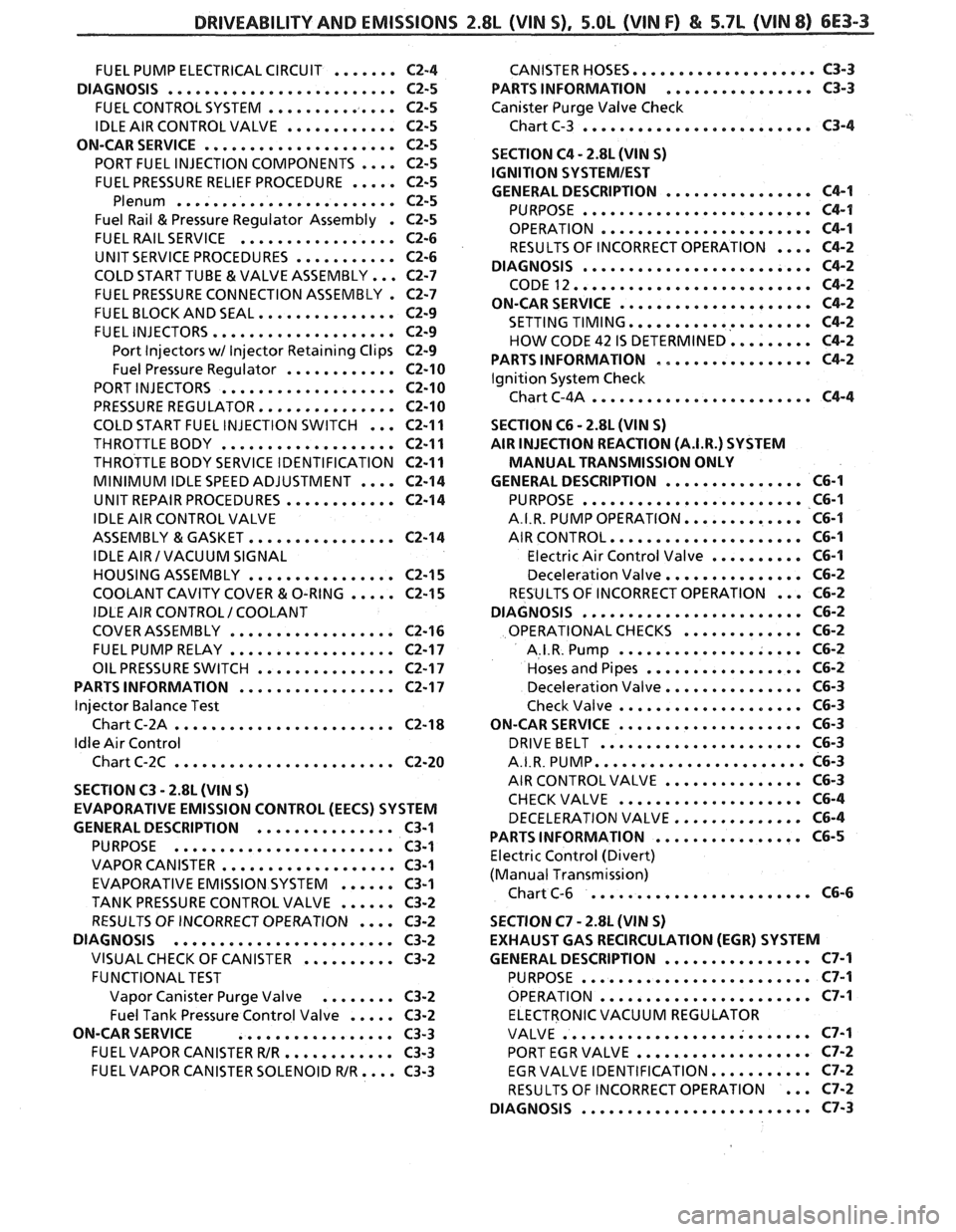
.................... FUEL PUMP ELECTRICAL CIRCUIT ....... C2-4 CANISTER HOSES C3-3
................ DIAGNOSIS ......................... C2-5 PARTS INFORMATION C3-3
FUEL CONTROL SYSTEM .............. C2-5 Canister Purge Valve Check
......................... IDLE AIR CONTROL VALVE ............ C2-5 Chart C-3 C3-4
ON-CAR SERVICE
..................... C2-5
.... PORT FUEL INJECTION COMPONENTS C2-5
FUEL PRESSURE RELIEF PROCEDURE ..... C2-5
Plenum ........................ C2-5
Fuel Rail & Pressure Regulator Assembly . C2-5
FUEL RAIL SERVICE ................. C2-6
UNIT SERVICE PROCEDURES ........... C2-6
COLD START TUBE & VALVE ASSEMBLY ... C2-7
FUEL PRESSURE CONNECTION ASSEMBLY . C2-7
FUEL BLOCK AND SEAL ............... C2-9
FUEL INJECTORS .................... C2-9
Port Injectors wl Injector Retaining Clips C2-9
Fuel Pressure Regulator ............ C2-10
PORT INJECTORS ................... C2-10
PRESSURE REGULATOR ............... C2-10
COLD START FUEL INJECTION SWITCH ...
THROTTLE BODY ...................
THROTTLE BODY SERVICE IDENTIFICATION
MINIMUM IDLE SPEED ADJUSTMENT
....
UNIT REPAIR PROCEDURES ............
IDLE AIR CONTROL VALVE
ASSEMBLY
& GASKET ................
IDLE AIR I VACUUM SIGNAL
HOUSING ASSEMBLY
................
COOLANT CAVITY COVER & O-RING .....
IDLE AIR CONTROL I COOLANT
COVER ASSEMBLY
..................
FUEL PUMP RELAY ..................
OIL PRESSURE SWITCH ...............
PARTS INFORMATION .................
Injector Balance Test
Chart C-2A
........................
Idle Air Control
Chart C-2C
........................
SECTION C3 . 2.8L (WIN S)
EVAPORATIVE EMISSION CONTROL (EECS) SYSTEM
GENERAL
DESCRIPTION ............... C3-1
PURPOSE ........................ C3-1
VAPOR CANISTER ................... C3-1
EVAPORATIVE EMISSION SYSTEM ...... C3-1
TANK PRESSURE CONTROL VALVE ...... C3-2
.... RESULTS OF INCORRECT OPERATION C3-2
DIAGNOSIS
........................ C3-2
VISUAL CHECK OF CANISTER .......... C3-2
FUNCTIONAL TEST
Vapor Canister Purge Valve
........ C3-2
..... Fuel Tank Pressure Control Valve C3-2
ON-CAR SERVICE
................. C3-3
FUEL VAPOR CANISTER WR ............ C3-3
FUEL VAPOR CANISTER SOLENOID WR .... C3-3
SECTION C4 . 2.8L (VIN S)
IGNITION
SQSTEMIEST
................ GENERAL DESCRIPTION C4-1
......................... PURPOSE C4-1
OPERATION ....................... C4-1
RESULTS OF INCORRECT OPERATION .... C4-2
DIAGNOSIS
......................... C4-2
CODE 12 .......................... C4-2
ON-CAR SERVICE ..................... C4-2
SETTING TIMING .................... C4-2
HOW CODE 42 IS DETERMINED ......... C4-2
PARTS INFORMATION ................. C4-2
Ignition System Check
Chart C-4A
........................ C4-4
SECTION C6 . 2.8L (VIN S)
AIR INJECTION REACTION (A.I.R.) SYSTEM
MANUAL TRANSMISSION ONLY
............... GENERAL DESCRIPTION C6-1
........................ PURPOSE C6-1
............. A.I.R. PUMP OPERATION C6-I
..................... AIR CONTROL C6-1
.......... Electric Air Control Valve C6-1
............... Deceleration Valve C6-2
... RESULTS OF INCORRECT OPERATION C6-2
........................ DIAGNOSIS C6-2
............. OPERATIONAL CHECKS C6-2
.................... A.I.R. Pump C6-2
................. Hoses and Pipes C6-2
............... Deceleration Valve C6-3
.................... Check Valve C6-3
.................... ON-CAR SERVICE C6-3
...................... DRIVEBELT C6-3
....................... A.I.R. PUMP C6-3
............... AIR CONTROL VALVE C6-3
.................... CHECKVALVE C6-4
DECELERATION VALVE .............. C6-4
................ PARTS INFORMATION C6-5
Electric Control (Divert)
(Manual Transmission)
........................ Chart C-6 C6-6
SECTION C7
. 2.8L (VIN S)
EXHAUST GAS RECIRCULATION (EGR) SYSTEM
GENERAL DESCRIPTION
................ C7-1
......................... PURPOSE C7-1
....................... OPERATION C7-I
ELECTRONIC VACUUM REGULATOR
........................... VALVE C7-1
................... PORT EGR VALVE C7-2
........... EGR VALVE IDENTIFICATION C7-2
... RESULTS OF INCORRECT OPERATION C7-2
......................... DIAGNOSIS C7-3
Page 650 of 1825
DRIVEABILITVAND EMISSIONS Z.$L (VIN 5). 5.OL (VIN F) & 5.7L (VIN 8) 6E3-5
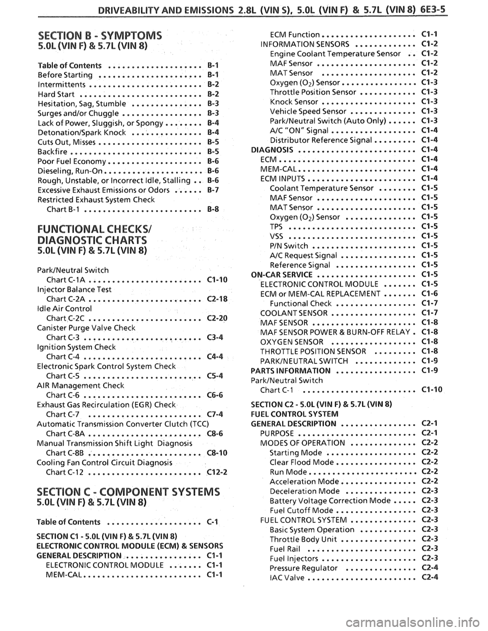
SECTION B . SYMPTOMS
5.OL (VIN F) & 5.7L (VIN 8)
.................... Table of Contents B-1
................... Before Starting ... B-1
. lntermittents .................... ... B-2
Hardstart .......................... B-2
............... Hesitation. Sag. Stumble 8-3
Surges andlor Chuggle ................. B-3
........ Lack of Power. Sluggish. or Spongy 8-4
DetonationISpark Knock ............... B-4
...................... Cuts Out. Misses €3-5
Backfire ............................ B-5
Poor Fuel Economy .................... B-6
Dieseling. Run.On ..................... 8-6
Rough. Unstable. or Incorrect Idle. Stalling . . B-6
Excessive Exhaust Emissions or Odors ...... B-7
Restricted Exhaust System Check
Chart
B-1 ......................... B-8
FUNCTIONAL CHECKS1
DIAGNO%"FIC CHARTS
5.OL (VIN F) & 5.7L (WIN 8)
ParkINeutral Switch
. Chart C-1A .................... ... C1-10
Injector Balance Test
Chart C-2A
........................ C2-18
Idle Air Control
Chart C-2C
........................ C2-20
Canister Purge Valve Check
Chart C-3
......................... C3-4
Ignition System Check
ChartC-4
......................... C4-4
Electronic Spark Control System Check
Chart C-5
......................... C5-4
AIR Management Check
Chart C-6
......................... C6-6
Exhaust Gas Recirculation (EGR) Check
Chart C-7
........................ C7-4
Automatic Transmission Converter Clutch (TCC)
Chart
6-814 ........................ C8-6
Manual Transmission Shift Light Diagnosis
Chart C-8B
........................ C8-10
Cooling Fan Control Circuit Diagnosis
Chart C- 1 2
........................ C12-2
SECTION C . COMP0NEN"I"SVSTEMS
5.OL (VIN F) & 5.7L (WIN 8)
Table of Contents .................... C-1
SECTION
C1 . 5.OL (VIN F) & 5.7L (VIN 8)
ELECTRONIC CONTROL MODULE (ECM)
81 SENSORS
GENERAL DESCRIPTION
................ C1-1
ELECTRONIC CONTROL MODULE ....... C1-1
MEM.CAL ......................... C1-1
................... ECM Function. C1-1
INFORMATION SENSORS ............. C1-2
Engine Coolant Temperature Sensor . . C1-2
..................... MAF Sensor C1-2
.................... MAT Sensor C1-2
Oxygen (Oz) Sensor ..............a. C1-3
Throttle Position Sensor ............ C1-3
.................... Knock Sensor C1-3
Vehicle Speed Sensor .............. C1-3
ParkINeutral Switch (Auto Only) ...... C1-3
.................. A/C "ON" Signal C1-4
Distributor Reference Signal ......... C1-4
DIAGNOSIS ......................... C1-4
ECM ............................. C1-4
MEM.CAL ......................... C1-4
ECM INPUTS ....................... C1-4
Coolant Temperature Sensor ........ C1-5
..................... MAF Sensor C1-5
..................... MAT Sensor C1-5
Oxygen (Oz) Sensor ............... C1-5
TPS ........................... C1-5
VSS ........................... C1-5
...................... PIN Switch C1-5
A/C Request Signal ................ C1-5
Reference Signal ................. C1-5
ON-CAR SERVICE ..................... C1-5
ELECTRONIC CONTROL MODULE ....... C1-5
ECM or MEM-CAL REPLACEMENT ....... C1-6
Functional Check ................. C1-7
COOLANTSENSOR .................. C1-7
MAF SENSOR ...................... C1-8
MAF SENSOR POWER & BURN-OFF RELAY . C1-8
OXYGEN SENSOR .................. C1-8
THROTTLE POSITION SENSOR ......... C1-8
PARKINEUTRAL SWITCH ............. C1-9
................. PARTS INFORMATION C1-9
ParkINeutral Switch
Chart
C-1 ..................... ... C1-10
SECTION C2 . 5.0L (WIN F) & 5.7L (WIN 8)
FUEL CONTROL SYSTEM
................ GENERAL DESCRIPTION C2-1
......................... PURPOSE C2-1
.............. MODES OF OPERATION CZ-2
................... Starting Mode C2-2
Clear Flood Mode ................. CZ-2
....................... Run Mode CZ-2
................ Acceleration Mode C2-2
............... Decelerat~on Mode C2-3
Battery Voltage Correction Mode ..... C2-3
................. Fuel Cutoff Mode C2-3
.............. FUEL CONTROL SYSTEM C2-3
............ Basic System Operation CZ-3
................ Throttle Body Unit CZ-3
....................... Fuel Rail C2-3
.................... Fuel Injectors CZ-3
............... Pressure Regulator C2-4
....................... IAC Valve 62-4
Page 655 of 1825
6E3-A-2 2.88, (VIM S) DRIVEABILITY AND EMISSIONS
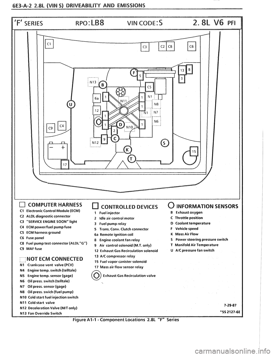
'Fa SERIES
COMPUTER HARNESS
C1 Electronic Control Module (ECM)
C2 ALDL diagnostic connector
C3 "SERVICE ENGINE
SOON" light
C4 ECM powerlfuel pump fuse
C5 ECM harness ground
C6 Fuse panel
C8 Fuel pump test connector
(ALDL"G")
C9 MAFfuse
CONTROLLED DEVICES
1 Fuel injector
2
Idle air control motor
3 Fuel pump relay
5 Trans. Conv. Clutch connector
6a Remote ignition coil
8 Engine coolant fan relay
9 Air control solenoid (M.T. only)
12 Exhaust Gas Recirculation solenoid
0 INFORMATION SENSORS
B Exhaust oxygen
C Throttle position D Coolant temperature
F Vehicle speed
K Mass Air Flow
S Power steering pressure switch
T Manifold Air Temperature
U AIC pressure fan switch
13 AIC compressor relay
,..,a :'"' NOT ECM 'ONNECTED 15 Fuel vapor canister solenoid N1 Crankcase vent valve (PCV) 17 bass air flow sensor relay N4 Engine temp. switch (telltale)
N5 Engine temp. sensor (gage) Exhaust Gas Recirculation valve
N6 Oil press. switch (telltale)
N7 Oil press, sensor (gage)
N8 Oil press. swich (fuel pump)
N10 Cold start fuel injection switch
N11 Cold start valve 7-29-87 N12 Deceleration Valve (MIT only)
N13 Fan Override Switch *5S 2127-6E
Figure Al-l - Component Locations 2.8L "F" Series
Page 658 of 1825
DRIVEABILITY AND EMISSIONS 2.8L (VIN S) 6E3-A-5
ECM
BRAKE SWITC
BACK
VIEW OF
AIR DIVERT SOLENOID
MANUALITRANS
IGNITION 12V
TANMIHT 250 ALTERNATOR
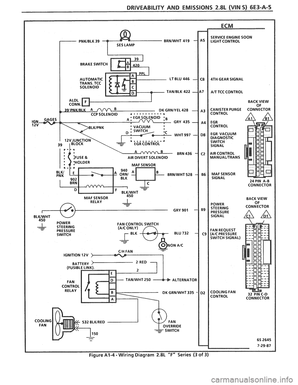
Figure A1-4 - Wiring Diagram 2.8L "F" Series (3 of 3)
Page 663 of 1825

6E3-A-"I 2.8L (VlN S) DRIVEABILITY AND EMlSSlONS
TO OIL PRESS. SW.
&FUEL PUMP RELAY
FUSE
81 HOLDER BATTERY 12 V .. m.. . n.
. . . . . . . . FUSIBLE LINK
439 PNWBLK
419 BRNNVHT
SERIAL
DATA
451
WHTJBLK
450 BLKNVHT
ALDL CONNECTOR
NO "SERVICE ENGlNE SOON" "LIGHT
2.8b (VIM 5) 'T" "SERIES (PORT)
Circuit Description:
There should always be a steady "Service Engine Soon" light when the ignition is "ON" and engine stopped.
Battery is supplied directly to the light bulb. The electronic control module
(ECNI) will control the light and
turn it "ON" by providing a ground path through CKT 419 to the ECM.
Test Description: Numbers below refer to circled
numbers on the diagnostic chart.
1. If the fuse in holder is blown refer to facing page of
Code
54 for complete circuit.
2. Using a test light connected to 12 volts probe each
of the system ground circuits to be sure a good
ground is present. See ECM terminal end view in
front of this section for
ECM pin locations of
ground circuits.
Diagnostic Aids:
Engine runs OK, check:
@ Faulty light bulb.
@ CKT 419 open.
@ Gage fuse blown.
This will result in no oil or
generator lights, seat belt reminder, etc. Engine
cranks but will not run.
@ Continuous battery - fuse or fusible link open.
@ ECM ignition fuse open.
@ Battery CKT 340 to ECM open.
@ Ignition CKT 439 to ECM open.
e Poor connection to ECM.
Solenoids and relays are turned "ON"
and "OFF"
by the ECM, using internal electronic switches called
"drivers". Each driver is part of a group of four called
"Quad-Drivers". Failure of one driver can damage
any other driver in the set. Solenoid and relay coil
resistance must measure more than 20 ohms. Less
resistance will cause early failure of the ECM
"driver".
Before replacing ECM, be sure to check the coil
resistance of all solenoids and relays controlled by the
ECM. See ECM wiring diagram for the
solenoid(s)
and relay(s) and the coil terminal identification.
Page 664 of 1825

DRIVEABILITY AND EMISSIONS 2.8L (VIN 5) 6E3-A-l l
CHART A-1
CLEAR CODES AND CONFIRM "CLOSED LOOP " OPERATION AND NO "SERVICE ENGINE SOON" LIGHT.
DISCONNECT
ECM CONNECTORS. BATTERY
FUSE (IN HOLDER)
IGNITION "ON".
PROBE
CUT 419, WITH TEST LIGHT
TO GROUND.
- GAGE FUSE. SHORT TO GROUND IN
- FAULTY BULB. @ PROBE CKT 340 & 439 CIRCUIT THAT HAD A
- OPEN CUT 419. WITH TEST LIGHT TO
- CKT 419 SHORTED TO
REPAIR OPEN IN
GROUNDS OR ECM. CIRCUIT THAT DID NOT
SEE QUAD DRIVER
CHECK (CHART
C-1).
Page 665 of 1825
6E3-A-92 2.8b (VIN SI DRIVEABILITY AND EMISSIONS
TO OIL PRESS. SW.
&FUEL PUMP RELAY
FUSE
& HOLDER BATTERY 12
V
.. am.. . FUSIBLE LINK 15 WAY
439
PNWBLK
- 419 BUNNVHT
SERIAL DATA
451
WHTIBLK
450 BLWHT
ALDL CONNECTOR
CHART A-2
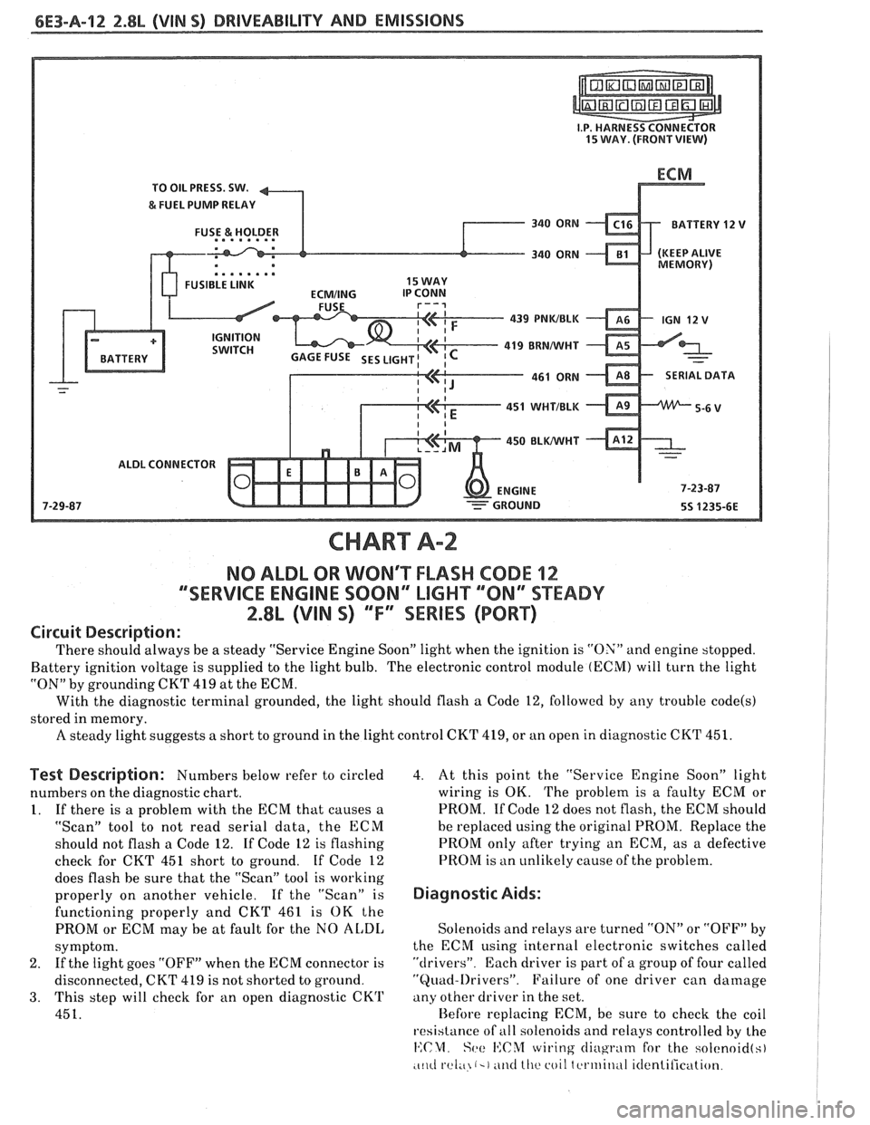
NO ALDL OR WONT FLASH CODE 12
""SERVICE ENGlNE SOON" MGHT ""8N13SPEADY
2.8L (VIN S) ""FYSERlES (PORT)
Circuit Description:
There should always be a steady "Service Engine Soon" light when the ignition is "ON" and engine stopped.
Battery ignition voltage is supplied to the light bulb. The electronic control module
(ECM) will turn the light
"ON" by grounding CKT
419 at the ECM.
With the diagnostic terminal grounded, the light should flash
a Code 12, followed by any trouble code(s)
stored in memory.
A steady light suggests a short to ground in the light control CKT 419, or an open in diagnostic CKT 451.
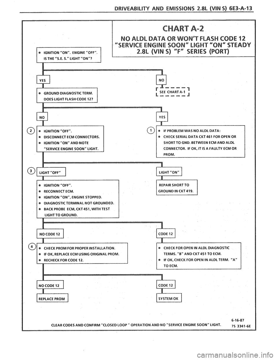
Test Description: Numbers below refer to circled
numbers on the diagnostic chart.
1. If there is a problem with the ECM that causes a
"Scan" tool to not read serial data, the ECM
should not flash a Code 12. If Code 12 is flashing
check for CKT
451 short to ground. If Code 12
does flash be sure that the "Scan" tool is working
properly on another vehicle. If the "Scan" is
functioning properly and CKT 461 is OK the
PROM or ECM may be at fault for the NO
AL,DI,
symptom.
2. If
the light goes "OFF" when the ECM connector is
disconnected, CKT 419 is not shorted to ground.
3. This step will check for an open diagnostic CKrl'
451.
4. At this point the "Service Engine Soon" light
wiring is OK. The problem is a faulty ECM or
PROM. If Code 12 does not flash, the ECM should
he replaced using the original PROM. Replace the
PROM only after trying an ECM, as a defective
PROM is an unlikely cause of the problem.
Diagnostic Aids:
Solenoids and relays are turned "ON" or "OFF" by
the ECM using internal electronic switches called
"drivers". Each driver is part of a group of four called
"Quad-l)rivers". Failure of one driver can damage
any other driver in the set.
Hefore replacing ECM, be sure to check the coil
resistance of
all solenoids and relays controlled by the
14:CM. Set: I':C%f wiring cliugrntn for the solcnoid(s)
.c~~cl rel;~ (-1 ~ititl lllc coil tcrtriitlul itlentilication.
Page 666 of 1825
DRIVEABILITY AND EMISSIONS 2.8b (VIN 5) 6E3-A-13
CHART A-2
NO ALDL DATA OR WONRT FLASH CODE 12
DISCONNECT ECM CONNECTORS.
IGNITION "ON" AND NOTE SHORT TO
GND. BETWEEN ECM AND ALDL
IGNITION "ON", ENGINE STOPPED.
KT
451, WITH TEST
IF OK, REPLACE ECM USING ORIGINAL PROM. TERMS.
"B" AND CKT 451 TO ECM.