1987 SUZUKI GRAND VITARA light
[x] Cancel search: lightPage 327 of 962
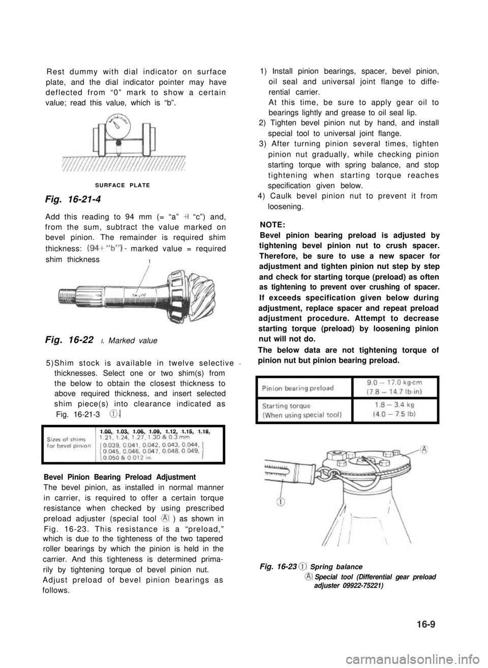
Rest dummy with dial indicator on surface
plate, and the dial indicator pointer may have
deflected from “0” mark to show a certain
value; read this value, which is “b”.
SURFACE PLATE
Fig. 16-21-4
Add this reading to 94 mm (= “a” + “c”) and,
from the sum, subtract the value marked on
bevel pinion. The remainder is required shim
thickness: (94+“b”) - marked value = required
shim thickness1
Fig. 16-22 I. Marked value
5)Shim stock is available in twelve selective L
thicknesses. Select one or two shim(s) from
the below to obtain the closest thickness to
above required thickness, and insert selected
shim piece(s) into clearance indicated as
Fig. 16-21-3 0.
1.00, 1.03, 1.06, 1.09, 1.12, 1.15, 1.18,
Bevel Pinion Bearing Preload Adjustment
The bevel pinion, as installed in normal manner
in carrier, is required to offer a certain torque
resistance when checked by using prescribed
preload adjuster (special tool @ ) as shown in
Fig. 16-23. This resistance is a “preload,”
which is due to the tighteness of the two tapered
roller bearings by which the pinion is held in the
carrier. And this tighteness is determined prima-
rily by tightening torque of bevel pinion nut.
Adjust preload of bevel pinion bearings as
follows.
1) Install pinion bearings, spacer, bevel pinion,
oil seal and universal joint flange to diffe-
rential carrier.
At this time, be sure to apply gear oil to
bearings lightly and grease to oil seal lip.
2) Tighten bevel pinion nut by hand, and install
special tool to universal joint flange.
3) After turning pinion several times, tighten
pinion nut gradually, while checking pinion
starting torque with spring balance, and stop
tightening when starting torque reaches
specification given below.
4) Caulk bevel pinion nut to prevent it from
loosening.
NOTE:
Bevel pinion bearing preload is adjusted by
tightening bevel pinion nut to crush spacer.
Therefore, be sure to use a new spacer for
adjustment and tighten pinion nut step by step
and check for starting torque (preload) as often
as tightening to prevent over crushing of spacer.
If exceeds specification given below during
adjustment, replace spacer and repeat preload
adjustment procedure. Attempt to decrease
starting torque (preload) by loosening pinion
nut will not do.
The below data are not tightening torque of
pinion nut but pinion bearing preload.
Fig. 16-23 @ Spring balance
@ Special tool (Differential gear preload
adjuster 09922-75221)
16-9
Page 357 of 962
Before giving a test pull to knuckle arm with a
spring balance in the alternative method, in-
stall a large amount of shims on each kingpin to
lighten preload on tapered roller bearing.
Keep on reading the torque, each time decreas-
ing shim thickness a little, and continue this
process until specified torque value is obtained.
(This process protects kingpins because it ensure
that no excessive pull will be applied to bearings
at the onset.) If the process fails to produce
specified torque, that is, if desired torque
resistance does not occur even when shim
thickness has been reduced to zero on each
kingpin, it means that bearings or kingpins are
excessively worn and need replacement.
NOTE:
l Read spring balance indication when knuckle
arm begins to turn. In other words, you are
to read “starting torque.”
l When checking knuckle arm starting torque,
be sure to have axle hub oil seal removed
and tighten king pin bolts to specified torque.
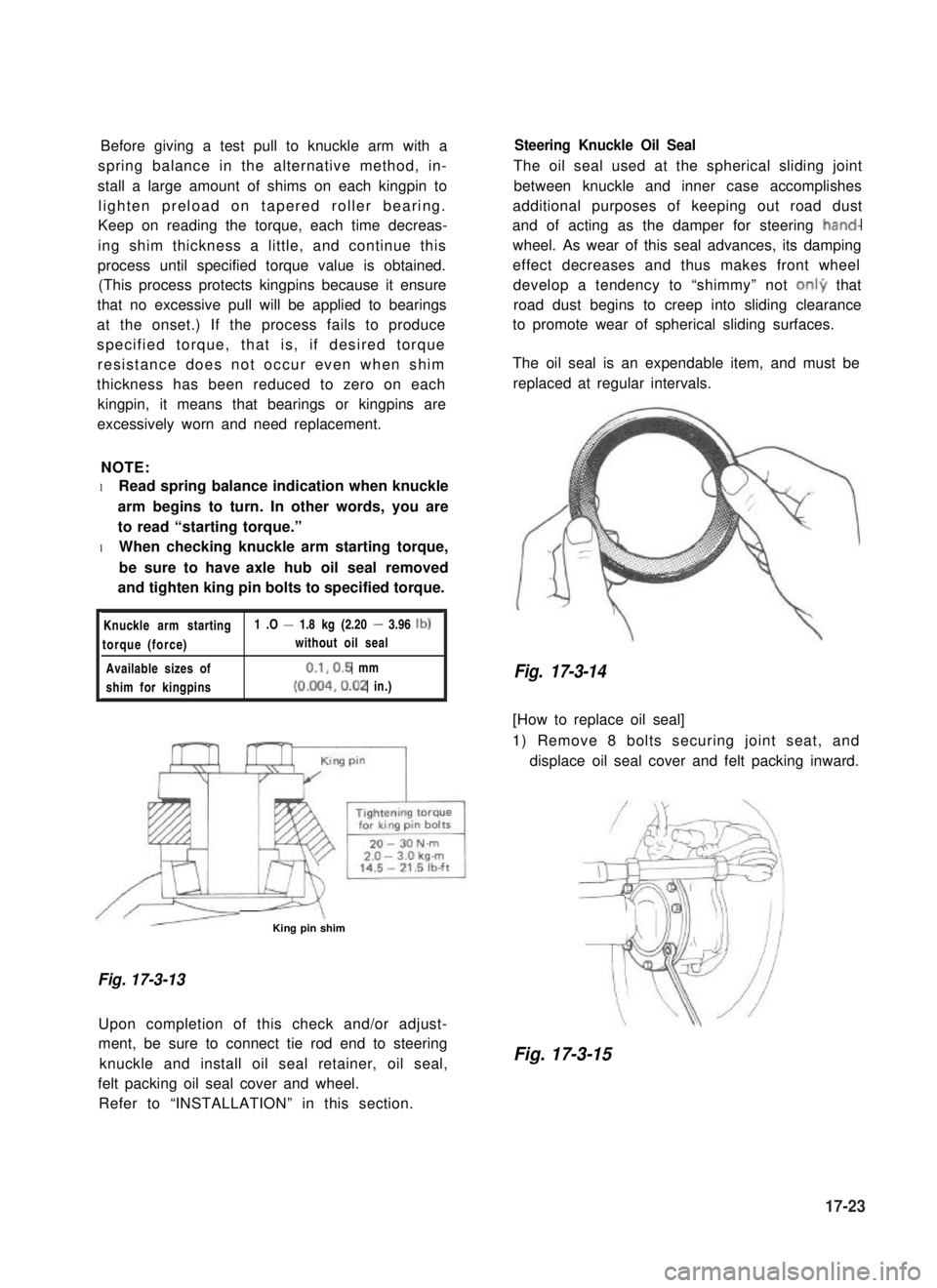
Knuckle arm starting1 .O - 1.8 kg (2.20 - 3.96 lb)
torque (force)without oil seal
Available sizes of0.1,0.5 mm
shim for kingpins(0.004,0.02 in.)
/r--QzL- -\King pin shim
Fig. 17-3-13
Upon completion of this check and/or adjust-
ment, be sure to connect tie rod end to steering
knuckle and install oil seal retainer, oil seal,
felt packing oil seal cover and wheel.
Refer to “INSTALLATION” in this section.
Steering Knuckle Oil Seal
The oil seal used at the spherical sliding joint
between knuckle and inner case accomplishes
additional purposes of keeping out road dust
and of acting as the damper for steering hand-
wheel. As wear of this seal advances, its damping
effect decreases and thus makes front wheel
develop a tendency to “shimmy” not onI9 that
road dust begins to creep into sliding clearance
to promote wear of spherical sliding surfaces.
The oil seal is an expendable item, and must be
replaced at regular intervals.
Fig. 17-3-14
[How to replace oil seal]
1) Remove 8 bolts securing joint seat, and
displace oil seal cover and felt packing inward.
Fig. 17-3-15
17-23
Page 384 of 962
/I
d-
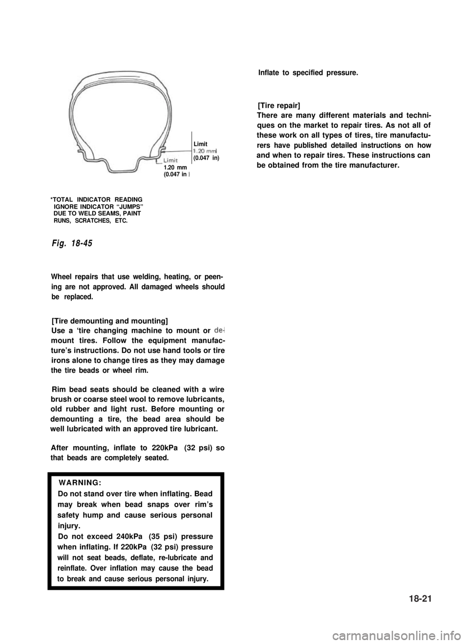
Limitl.Mmm(0.047 in)
1.20 mm(0.047 in 1
*TOTAL INDICATOR READINGIGNORE INDICATOR “JUMPS”DUE TO WELD SEAMS, PAINTRUNS, SCRATCHES, ETC.
Fig. 18-45
Wheel repairs that use welding, heating, or peen-
ing are not approved. All damaged wheels should
be replaced.
[Tire demounting and mounting]
Use a ‘tire changing machine to mount or de-
mount tires. Follow the equipment manufac-
ture’s instructions. Do not use hand tools or tire
irons alone to change tires as they may damage
the tire beads or wheel rim.
Rim bead seats should be cleaned with a wire
brush or coarse steel wool to remove lubricants,
old rubber and light rust. Before mounting or
demounting a tire, the bead area should be
well lubricated with an approved tire lubricant.
After mounting, inflate to 220kPa (32 psi) so
that beads are completely seated.
WARNING:
Do not stand over tire when inflating. Bead
may break when bead snaps over rim’s
safety hump and cause serious personal
injury.
Do not exceed 240kPa (35 psi) pressure
when inflating. If 220kPa (32 psi) pressure
will not seat beads, deflate, re-lubricate and
reinflate. Over inflation may cause the bead
to break and cause serious personal injury.1
Inflate to specified pressure.
[Tire repair]
There are many different materials and techni-
ques on the market to repair tires. As not all of
these work on all types of tires, tire manufactu-
rers have published detailed instructions on how
and when to repair tires. These instructions can
be obtained from the tire manufacturer.
18-21
Page 406 of 962
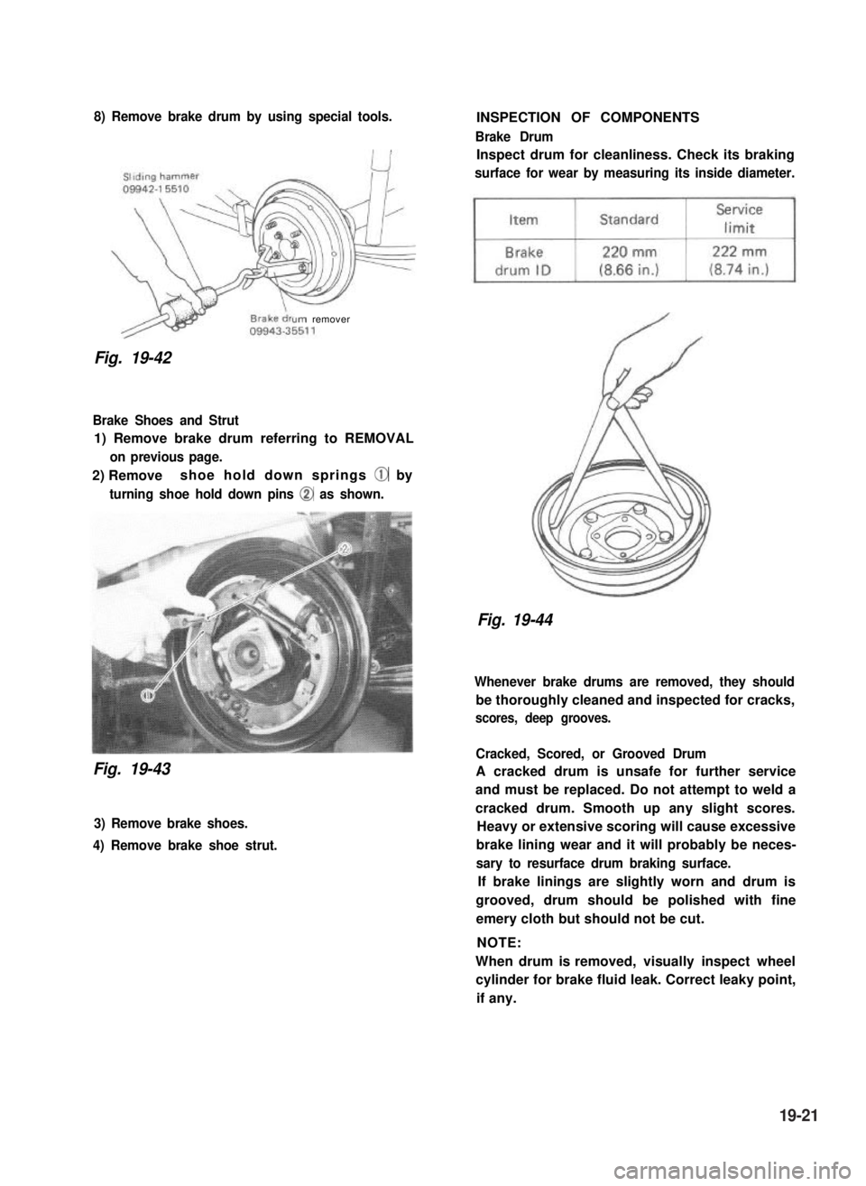
8) Remove brake drum by using special tools.
urn remover
Fig. 19-42
Brake Shoes and Strut
1) Remove brake drum referring to REMOVAL
on previous page.
2) Removeshoe hold down springs @ by
turning shoe hold down pins @ as shown.
Fig. 19-43
3) Remove brake shoes.
4) Remove brake shoe strut.
INSPECTION OF COMPONENTS
Brake Drum
Inspect drum for cleanliness. Check its braking
surface for wear by measuring its inside diameter.
Fig. 19-44
Whenever brake drums are removed, they should
be thoroughly cleaned and inspected for cracks,
scores, deep grooves.
Cracked, Scored, or Grooved Drum
A cracked drum is unsafe for further service
and must be replaced. Do not attempt to weld a
cracked drum. Smooth up any slight scores.
Heavy or extensive scoring will cause excessive
brake lining wear and it will probably be neces-
sary to resurface drum braking surface.
If brake linings are slightly worn and drum is
grooved, drum should be polished with fine
emery cloth but should not be cut.
NOTE:
When drum is removed, visually inspect wheel
cylinder for brake fluid leak. Correct leaky point,
if any.
19-21
Page 417 of 962
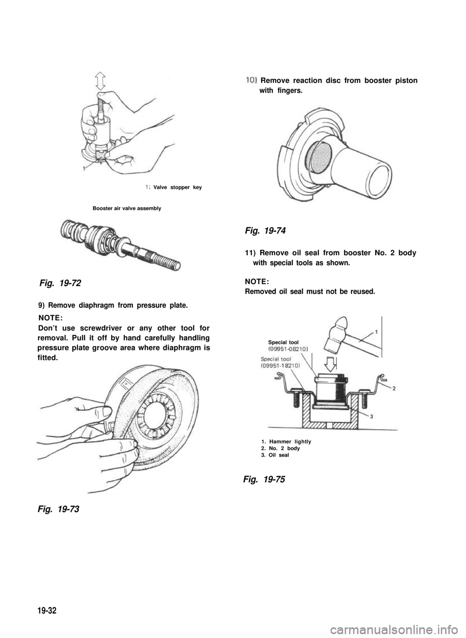
1. Valve stopper key
Booster air valve assembly
Fig. 19-72
10) Remove reaction disc from booster piston
with fingers.
Fig. 19-74
11) Remove oil seal from booster No. 2 body
with special tools as shown.
NOTE:
Removed oil seal must not be reused.
;1
Special tool~09951-082101
Special toolk
109951~W~lO,\ 0
9) Remove diaphragm from pressure plate.
NOTE:
Don’t use screwdriver or any other tool for
removal. Pull it off by hand carefully handling
pressure plate groove area where diaphragm is
fitted.
1. Hammer lightly2. No. 2 body3. Oil seal
Fig. 19-75
Fig. 19-73
19-32
Page 427 of 962
19-8. MAINTENANCE SERVICE
ROAD TESTING BRAKES
Brakes should be tested on dry, clean, smooth
and reasonably level roadway which is not
crowned. Road test brakes by making brake
applications with both light and heavy pedal
forces at various speeds to determine if the car
stops evenly and effectively.
Also drive car to see if it leads to one side or the
other without brake application. If it does,
check tire pressure, front end alignment and
front suspension attachments for looseness.
See diagnosis chart for other causes.
BRAKE FLUID LEAKS
Check master cylinder fluid levels. While a slight
drop in reservoir level does result from normal
lining wear, an abnormally low level indicates a
leak in the system.In such a case, check the
entire brake system for leakage. If even a slight
evidence of leakage is noted, the cause should be
corrected or defective parts should be replaced.
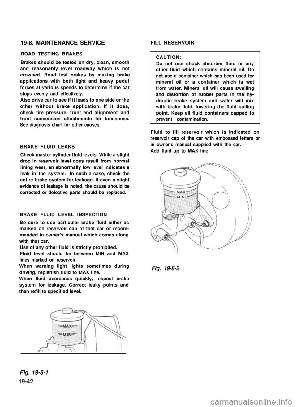
BRAKE FLUID LEVEL INSPECTION
Be sure to use particular brake fluid either as
marked on reservoir cap of that car or recom-
mended in owner’s manual which comes along
with that car.
Use of any other fluid is strictly prohibited.
Fluid level should be between MIN and MAX
lines marked on reservoir.
When warning light lights sometimes during
driving, replenish fluid to MAX line.
When fluid decreases quickly, inspect brake
system for leakage. Correct leaky points and
then refill to specified level.
FILL RESERVOIR
CAUTION:
Do not use shock absorber fluid or any
other fluid which contains mineral oil. Do
not use a container which has been used for
mineral oil or a container which is wet
from water. Mineral oil will cause swelling
and distortion of rubber parts in the hy-
draulic brake system and water will mix
with brake fluid, lowering the fluid boiling
point. Keep all fluid containers capped to
prevent contamination.
Fluid to fill reservoir which is indicated on
reservoir cap of the car with embossed letters or
in owner’s manual supplied with the car.
Add fluid up to MAX line.
Fig. 19-8-2
Fig. 19-8-1
19-42
Page 428 of 962
BRAKE PEDAL FREE HEIGHT ADJUSTMENT
Brake pedal height is normal if brake pedal is
as high as clutch pedal.
1) When booster push rod clevis has been
reinstalled, it is important that measurement
between booster mounting surface (with a
gasket attached) and the center of clevis
pin hole is adjusted within 125.5 mm -
126.5 mm (4.94 - 4.98 in.). (See page
19-37.)
2) When stop light switch has been removed,
refer to the following STOP LIGHT SWITCH
ADJUSTMENT for proper installation.
The services in above steps 1) and 2) may
affect brake pedal height.
STOP LIGHT SWITCH ADJUSTMENT
Adjustment should be made as follows when
installing the switch.
Pull up brake pedal toward you and while
holding it there, adjust switch position so that
clearance between the end of thread and brake
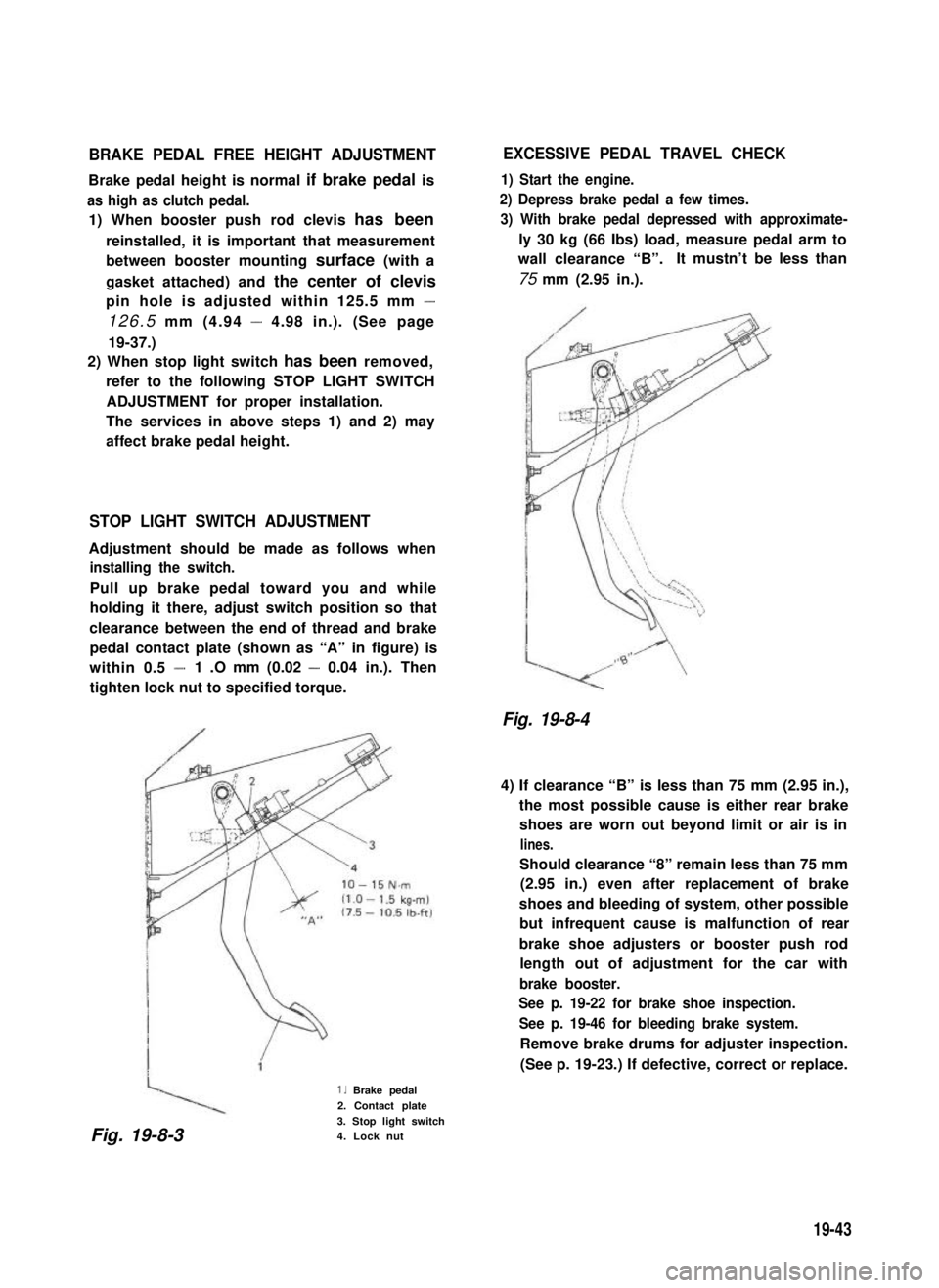
pedal contact plate (shown as “A” in figure) is
within 0.5 -1 .O mm (0.02 - 0.04 in.). Then
tighten lock nut to specified torque.
1. Brake pedal
2. Contact plate
3. Stop light switch4. Lock nut
EXCESSIVE PEDAL TRAVEL CHECK
1) Start the engine.
2) Depress brake pedal a few times.
3) With brake pedal depressed with approximate-
ly 30 kg (66 Ibs) load, measure pedal arm to
wall clearance “B”.It mustn’t be less than
75 mm (2.95 in.).
Fig. 19-8-4
4) If clearance “B” is less than 75 mm (2.95 in.),
the most possible cause is either rear brake
shoes are worn out beyond limit or air is in
lines.
Should clearance “8” remain less than 75 mm
(2.95 in.) even after replacement of brake
shoes and bleeding of system, other possible
but infrequent cause is malfunction of rear
brake shoe adjusters or booster push rod
length out of adjustment for the car with
brake booster.
See p. 19-22 for brake shoe inspection.
See p. 19-46 for bleeding brake system.
Remove brake drums for adjuster inspection.
(See p. 19-23.) If defective, correct or replace.
Fig. 19-8-3
19-43
Page 429 of 962
BRAKE HOSE AND PIPE INSPECTION
Hose
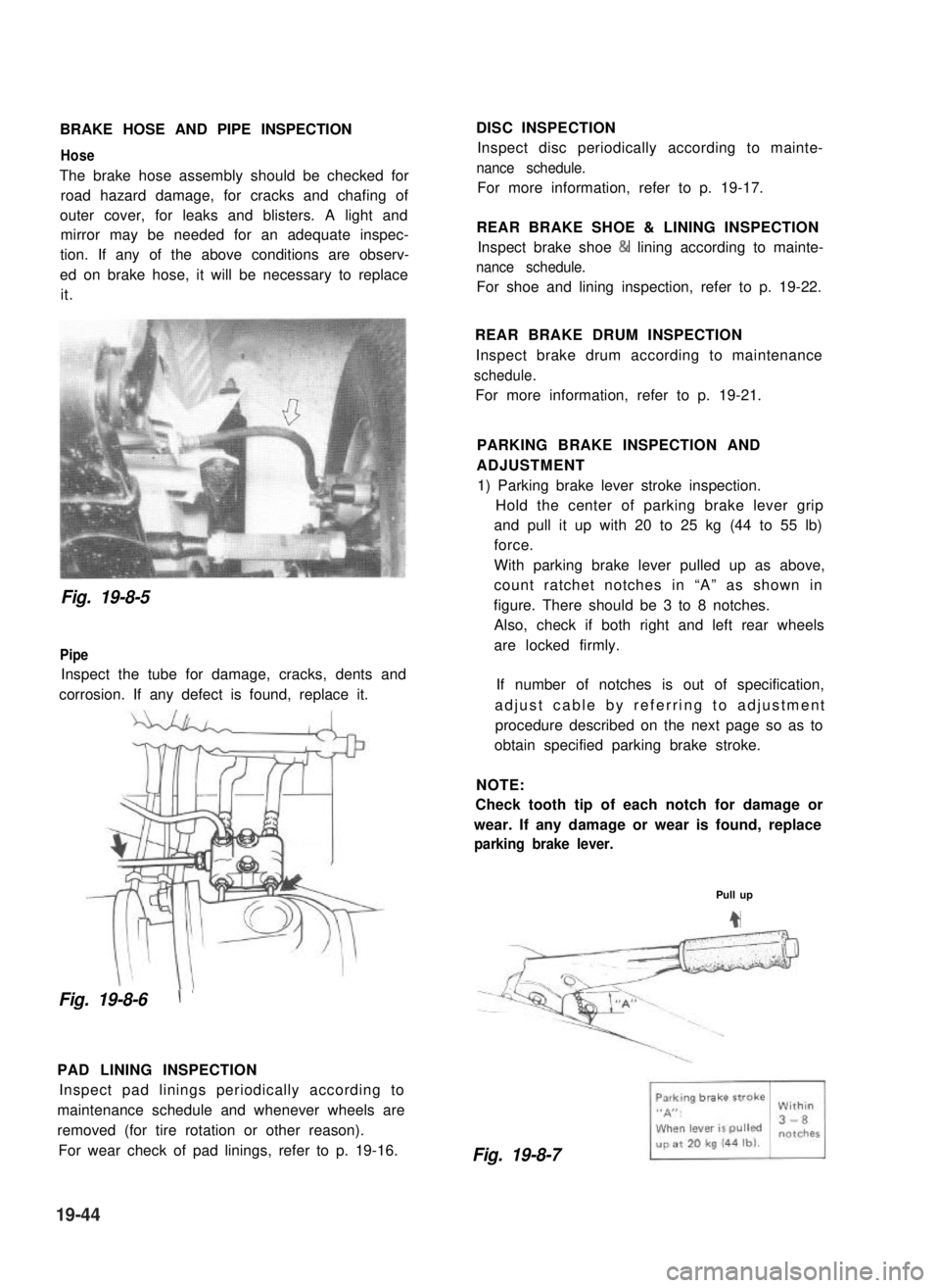
The brake hose assembly should be checked for
road hazard damage, for cracks and chafing of
outer cover, for leaks and blisters. A light and
mirror may be needed for an adequate inspec-
tion. If any of the above conditions are observ-
ed on brake hose, it will be necessary to replace
it.
DISC INSPECTION
Inspect disc periodically according to mainte-
nance schedule.
For more information, refer to p. 19-17.
REAR BRAKE SHOE & LINING INSPECTION
Inspect brake shoe & lining according to mainte-
nance schedule.
For shoe and lining inspection, refer to p. 19-22.
Fig. 19-8-5
Pipe
Inspect the tube for damage, cracks, dents and
corrosion. If any defect is found, replace it.
Fig. 19-8-6\ ’
PAD LINING INSPECTION
Inspect pad linings periodically according to
maintenance schedule and whenever wheels are
removed (for tire rotation or other reason).
For wear check of pad linings, refer to p. 19-16.
REAR BRAKE DRUM INSPECTION
Inspect brake drum according to maintenance
schedule.
For more information, refer to p. 19-21.
PARKING BRAKE INSPECTION AND
ADJUSTMENT
1) Parking brake lever stroke inspection.
Hold the center of parking brake lever grip
and pull it up with 20 to 25 kg (44 to 55 lb)
force.
With parking brake lever pulled up as above,
count ratchet notches in “A” as shown in
figure. There should be 3 to 8 notches.
Also, check if both right and left rear wheels
are locked firmly.
If number of notches is out of specification,
adjust cable by referring to adjustment
procedure described on the next page so as to
obtain specified parking brake stroke.
NOTE:
Check tooth tip of each notch for damage or
wear. If any damage or wear is found, replace
parking brake lever.
Pull up
4
Fig. 19-8-7
19-44