Page 458 of 962

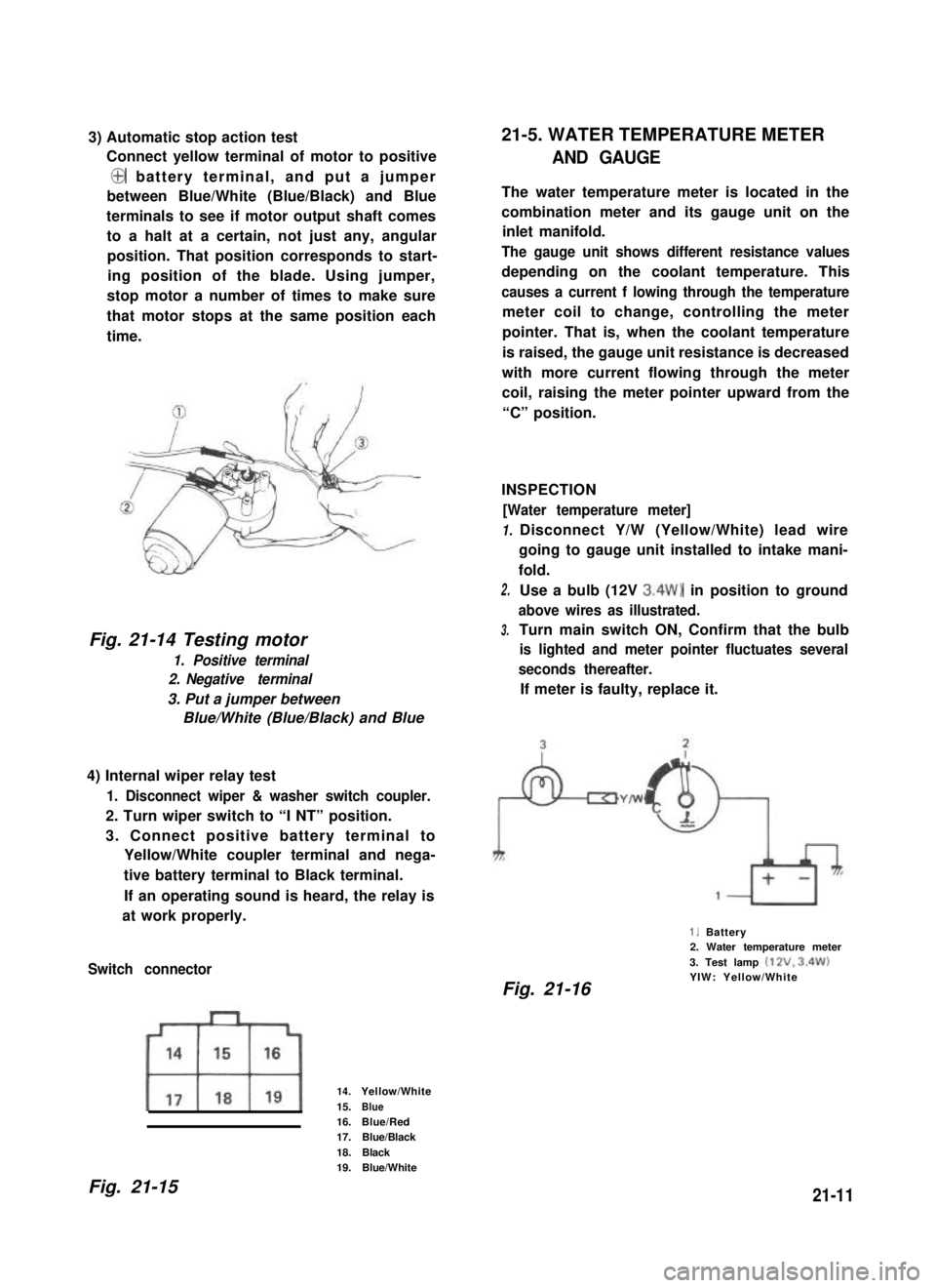
3) Automatic stop action test
Connect yellow terminal of motor to positive
@ battery terminal, and put a jumper
between Blue/White (Blue/Black) and Blue
terminals to see if motor output shaft comes
to a halt at a certain, not just any, angular
position. That position corresponds to start-
ing position of the blade. Using jumper,
stop motor a number of times to make sure
that motor stops at the same position each
time.
Fig. 21-14 Testing motor
1. Positive terminal
2. Negative terminal
3. Put a jumper between
Blue/White (Blue/Black) and Blue
4) Internal wiper relay test
1. Disconnect wiper & washer switch coupler.
2. Turn wiper switch to “I NT” position.
3. Connect positive battery terminal to
Yellow/White coupler terminal and nega-
tive battery terminal to Black terminal.
If an operating sound is heard, the relay is
at work properly.
Switch connector
14.Yellow/White
15.Blue16.Blue/Red17.Blue/Black
18.Black19.Blue/White
21-5. WATER TEMPERATURE METER
AND GAUGE
The water temperature meter is located in the
combination meter and its gauge unit on the
inlet manifold.
The gauge unit shows different resistance values
depending on the coolant temperature. This
causes a current f lowing through the temperature
meter coil to change, controlling the meter
pointer. That is, when the coolant temperature
is raised, the gauge unit resistance is decreased
with more current flowing through the meter
coil, raising the meter pointer upward from the
“C” position.
INSPECTION
[Water temperature meter]
1.
2.
3.
Disconnect Y/W (Yellow/White) lead wire
going to gauge unit installed to intake mani-
fold.
Use a bulb (12V 3.4W) in position to ground
above wires as illustrated.
Turn main switch ON, Confirm that the bulb
is lighted and meter pointer fluctuates several
seconds thereafter.
If meter is faulty, replace it.
1. Battery2. Water temperature meter
3. Test lamp (12V. 3.4W)YIW: Yellow/WhiteFig. 21-16
Fig. 21-1521-11
Page 459 of 962
![SUZUKI GRAND VITARA 1987 Service Repair Manual [Gauge unit] 21-6. FUEL LEVEL METER AND GAUGE
Warm up gauge unit. Thus make sure its resis-
tance is decreased with increase of temperature.
Temperature and resistance relationship can be
plotted in a SUZUKI GRAND VITARA 1987 Service Repair Manual [Gauge unit] 21-6. FUEL LEVEL METER AND GAUGE
Warm up gauge unit. Thus make sure its resis-
tance is decreased with increase of temperature.
Temperature and resistance relationship can be
plotted in a](/manual-img/20/57437/w960_57437-458.png)
[Gauge unit] 21-6. FUEL LEVEL METER AND GAUGE
Warm up gauge unit. Thus make sure its resis-
tance is decreased with increase of temperature.
Temperature and resistance relationship can be
plotted in a graph as shown below.
The fuel level meter circuit consists of the fuel
level meter installed inside the combination
meter and the fuel level gauge installed to the
fuel tank.
Fig. 21-17
wTemp.
Fig. 21-18 Resistance- Temp. Relationship
Temperature
50°C (122°F)
80°C (176°F)
100°C (212°F)
Resistance
133.9 -178.9 f-i
47.5-56.8 !a
26.2 -29.3 52
Current flowing through the meter coil is
changed to control the meter pointer. That is,
when fuel is full, the fuel level gauge unit
resistance is decreased with more current flowing
into the meter coil, causing the meter pointer
to point at the “F” position.
INSPECTION
[Fuel level meter]
1. Disconnect Y/R (Yellow/Red) lead wire
going to gauge unit.
2. Use a bulb (12V 3.4W) in position to ground
above lead wire as illustrated.
3. Turn ignition switch ON.
Make sure the bulb is lighted and meter
pointer fluctuates several seconds thereafter.
If meter is faulty, replace it.
Fig. 21-191. Battery2. Fuel level meter
3. Test lamp (12V. 3.4%‘)YR : Yellow/Red
NOTE:
Wind sealing tape on screw threads of gauge
before installing gauge to intake manifold.
21-12
Page 462 of 962

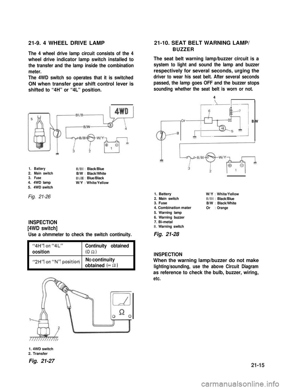
21-9. 4 WHEEL DRIVE LAMP21-10. SEAT BELT WARNING LAMP/
BUZZERThe 4 wheel drive lamp circuit consists of the 4
wheel drive indicator lamp switch installed to
the transfer and the lamp inside the combination
meter.
The 4WD switch so operates that it is switched
ON when transfer gear shift control lever is
shifted to “4H” or “4L” position.
The seat belt warning lamp/buzzer circuit is a
system to light and sound the lamp and buzzer
respectively for several seconds, urging the
driver to wear his seat belt. After several seconds
passed, the lamp goes OFF and the buzzer stops
sounding whether the seat belt is worn or not.
1.BatteryB/B1:Black/Blue2.Main switchB/W:Black/White3.FuseBI/B:Blue/Black4.4WD lampW/Y:White/Yellow5.4WD switch
Fig. 21-26
INSPECTION
[4WD switch]
Use a ohmmeter to check the switch continuity.
I
“4H” or “4L”Continuity obtained
oosition(052)I
I
#,2HM or ##N## positionNO continuity
obtained (- 52 1I
CL-
01
8
4\II
B/W
1. Battery
2. Main switch3. Fuse
4. Combination mater
5. Warning lamp
6. Warning buzzer7. Bi-metal8. Warning switch
W/Y:White/Yellow
BIBI:Black/BlueB/W:Black/White
Or:Orange
Fig. 21-28
INSPECTION
When the warning lamp/buzzer do not make
lighting/sounding, use the above Circuit Diagram
as reference to check the bulb, buzzer, wiring,
etc.
1. 4WD switch
2. Transfer
Fig. 21-2721-15
Page 465 of 962
21-14. FUSE BOX
The fuses in the fuse box is wired as follows.
Head light (R)
Fuse box
Head light (L)Battery7
Horn, Interior light, Door warning
buzzer, ctock (optional)
Stop light
Hazard warning light-W/GI10AW,YI
Cigarette lighter (optional),
Radio (optional)
-w’B++-B7Ignition coil, Fuel cut solenoid,
TWSV, MCSV, vent solenoid,-B/W15A
3
BIBI-
ECM
Heater blower motor-L9
Rear defogger (optional)-Y/G15A
Wiper motor, washer motor-Y/El15A:: BIBI-
Turn signal light, Back-up light-Y10A
Illumination light, License light,
Meter illumination light
-R’y++lFront position and tail light (RI,
Side marker light (RI--RIG5A:: RIB
Lighting switch
Front position and tail light (L), --R,a,
Side marker light (L)
-t
-c
Mainswitch
Tostarter
B/R--,
-
21-18
Page 466 of 962
21-15. WIRING HARNESS ROUTING
When reinstalling wire harness, be careful for the following.
l When doing wiring harness related work, make always sure to disconnect battery negative cable from
battery.
l Clamp wire harness securely at prescribed positions.
l Try to route wire harness so as to avoid contact with other parts as much as possible. Use special care
not to let it contact sharp edges of body or other parts.
0 Connect connectors securely.
Engine Room Wiring
1.Wire harness No. 2
2.Battery3. To starter, alternator, head light, small light, horn and etc.
4. To license light, stop/tail light, 4WD switch
5.Earth
6.To wiring harness No.17. To head light, small light, etc.
8.To distributor
9. To ignition coil
10. To back up light switch
11. To fifth switch
12.To TWSV
13.Duty check coupler
14. Thermal engine room switch
15. HAC
16.Ignition coil
17.Brake fluidreservoir
Fig. 27-37
21-19
Page 467 of 962
1.Battery2.Fusible link
3.To starter
4. To starter, alternator, etc
5.Earth6. Earth (To starter mounting bolt)7.Wiring harnessNo.2
64
1
I
1.From wire harnessNo.22. TWSV (Three way solenoid valve)
3. Water temperautre gauge4.Alternator5.Intake manifold
6.Clamp
7.ToVSV6.Thermal switch
9. Mount this terminal horizontal-ly as shown
10.Thermostat cap
1. Wire harness No. 2
2. To distributor
3. To fifth switch4. To back up light switch5. To ignition coil6. Condensor
7. Noise suppressor filter(Clamp it toward engineroom so as to prevent itfrom contacting dashpanel edge.)6. Earth9. To license light, stop/taillight, 4WD switch
10. Ignition coil
11. Distributor12. To wire harness No. 2
13. Ignition coil cap
Fig. 21-38
21-20
Page 468 of 962
Fig. 21-39
Instrument Panel Wiring
1.Wire harness No.2
2. Side marker light3.Head light
4.Earth
5.Washer motor
6. To oil pressure gauge
7. To combination light
16
1.Wire harness No. 1
2.To wire~harness No.2
3.To wire harness No.2
4. To fuse box5.Horn relay
6. To combination switch7.To clutch switch
8.Tostop lampswitch15.Doorwarning buzzer
9. To heater blower motor16. Check relay
10.Toradio17.To wipermotor
Il. To heater fan switch18.To illumination lamp
12. To cigar light19. To optional meter
13.Toradio20.Toclock
14.ToECM21.Tometer
Fig. 21-40
21-21
Page 471 of 962
ModelsConvertible/Hardtop ITEM
Tail/Brake light
Side marker light
12V, 3132 cp
12V, 3.8W
License plate light12V,4cp
Back-up light12V32cp
Interior light12v, 5wIMeter pilot light12V,1.4W
Main fuse
Fuse box
POWER TRANSMISSION
Clutch type
Transmission type
Final reduction ratio
0.5 mm2 (fusible link)
1 O/l Of 1 O/l 0/10/1 5/15/l 5/15/l 5/l 0/5/5/5A
Dry, single disc
5-forward all synchromesh, 1 reverse
3.727
Gear ratios
Transfer gear
ratios
Overall reduction ratios:
low3.652
2nd1.947
3rd1.423
4th
1 0.864
reverse1 3.466Ilow range
high range
2.268
1.409
Ilow1 30.8691
Low range
2nd16.457
3rd12.028
4th8.452
t5th7.303I
reverse29.297
low19.177
2nd10.224
3rd7.472
I
-.I4th5.251._..
5th
reverse
4.537
18.201
High range
22-2