1987 SUZUKI GRAND VITARA light
[x] Cancel search: lightPage 235 of 962
10-l. ALTERNATOR
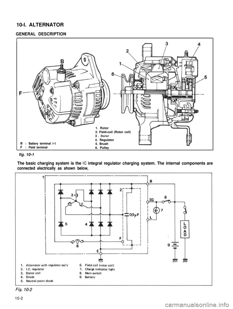
GENERAL DESCRIPTION
B :F :Battery terminal (+)
-1. Rotor
2. Field-coil (Rotor coil)
3. Stator
4. Regulator5. BrushField terminal6. Pulley
The basic charging system is the IC integral regulator charging system. The internal components are
connected electrically as shown below,
ThTh*
1. Alternator with regulator ass’y6. Field coil (rotor coil)
2.IX. regulator7.Charge indicatorlight
3.Stator coil8.Mein switch
4.Diode9.Battery5. Neutral point diode
fig. 10-1
10-2
Page 237 of 962
A. Faulty Indicator Lamp Operation
Problem
Charge light does not light
with ignition ON and engine
off
Charge light does not go out
with engine running
(battery requires frequent
re-
charging) Possible cause
Correcti on
Fuse blown
Check fuse
Light burned outReplace light
Wiring connection loose Tighten loose connections
IC regulator faultyReplace IC regulator
Drive belt loose or worn Adjust or replace drive belt
Battery cables loose, corroded or worn Repair or replace cables
IC regulator or alternator faultyCheck charging system
Wiring faulty.Repair wiring
B. Undercharged Battery a. Voltmeter
This condition, as shown by slow cranking or indicator clear with red dot, can be caused by
one or more of the following conditions even
though the indicator lamp may be operating
normally. The following procedures also apply
to cars with a voltmeter.
1) Insure that the undercharged condition has
not been caused by accessories left on for
extended period.
2) Check drive belt for proper tension.
3) If a battery defect is suspected, refer to
latter part of this section, p. 10-l 0 - p, 1 O-
11.
4) Inspect wiring for defects. Check all connec- tions for tightness and cleanliness, including
slip connectors at alternator and bulkhead,
and battery cable connections at battery,
starter and ignition ground cable.
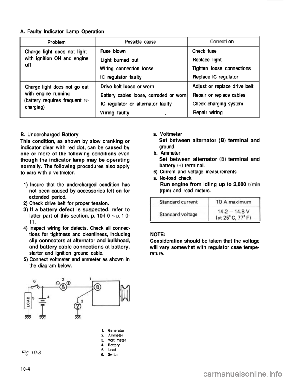
5) Connect voltmeter and ammeter as shown inthe diagram below.
Set between alternator (B) terminal and
ground.
b. Ammeter
Set between alternator (B) terminal and
battery (+) terminal.
6) Current and voltage measurements
a. No-load check
Run engine from idling up to 2,000 r/min
(rpm) and read meters.
NOTE:
Consideration should be taken that the voltage
will vary somewhat with regulator case tempe-
rature.
Fig. 10-3
10-4
1.Generator
2.Ammeter
3. Volt meter
4. Battery
6. Load
6. Switch
Page 244 of 962
![SUZUKI GRAND VITARA 1987 Service Repair Manual [Carrier and hold-down]
The battery carrier and hold-down clamp should
be clean and free from corrosion before instal-
ling the battery. The carrier should be in good
condition so that it will support SUZUKI GRAND VITARA 1987 Service Repair Manual [Carrier and hold-down]
The battery carrier and hold-down clamp should
be clean and free from corrosion before instal-
ling the battery. The carrier should be in good
condition so that it will support](/manual-img/20/57437/w960_57437-243.png)
[Carrier and hold-down]
The battery carrier and hold-down clamp should
be clean and free from corrosion before instal-
ling the battery. The carrier should be in good
condition so that it will support the battery
securely and keep it level.
Make certain there are no parts in carrier before
installing the battery.
To prevent the battery from shaking in its
carrier, the hold-down bolts should be tight but
not over tightened.
[Visual inspection]
Check for obvious damage, such as cracked or
broken case or cover, that could permit loss of
electrolyte. If obvious damage is noted, replace
the battery. Determine cause of damage and
correct as needed.
Check the battery terminal and cords for corro-
sion. If any, it should be cleaned.
[Built-in indicator]
This sealed battery has a built-in temperature
compensated indicator in the top of the battery.
This indicator is to be used with the following
diagnostic procedure. When observing the
indicator, make sure that the battery has a clean
top. A light may be needed in some poorly-lit
areas.
Under normal operation, two indications can
be seen
2
Clear
RedCHARGING
NECESSARY
Fig. lo-23
l Clear with Red Dot
This means the discharging battery. In this case,
charge the battery until the indicator will be
blue with red dot. The charging and electrical
systems should also be checked at this time. If
any defective is found, correct it. While charging
it, if the battery feels hot 52°C (125” F), or if
violent gassing or spewing of electrolyte through
the vent hole occurs, discontinue charging or
reduce charging rate.
[Jump starting in case of emergency with
auxiliary (booster) battery]
NOTE:
l Do not push or tow the vehicle to start.
Damage to the emission system and/or to
other parts of the vehicle may result.
8 Both booster and discharged battery should
be treated carefully when using jumper cables.
Follow the procedure outlined below, being
careful not to cause sparks:
CAUTION:
l Departure from these conditions or the
procedure below could result in: (1)
Serious personal injury (particularly to
eyes) or property damage from such
causes as battery explosion, battery acid,
or electrical burns; and/or (2) damage to
electronic components of either vehicle.
l Never expose battery to open flame or
electric spark-batteries generate a gas
which is flammable and explosive.
l Remove rings,watches,and other
jewelry. Wear approved eye protection.
l Do not allow battery fluid to contact
eyes, skin, fabrics, or painted surfaces -
fluid is a corrosive acid. Flush any con-
tacted area with water immediately and
thoroughly. Be careful that metal tools
or jumper cables do not contact the
positive battery terminal (or metal in
contact with it) and any other metal on
the car, because a short circuit could
occur. Batteries should always be kept
out of the reach of children.
1) Set parking brake and place transmission in
neutral. Turn off the ignition, turn off lights
and all other electrical loads.
2) Check electrolyte level. If level is below low
level line, replace battery.
NOTE:
When jump starting an engine with charging
equipment, be sure equipment used is 12volt
and negative ground. Do not use 24volt charging
equipment. Using each equipment can cause
serious damage to the electrical system or
electronic parts.
10-11
Page 265 of 962
13-3. DISMOUNTINGIn Passenger Compartment
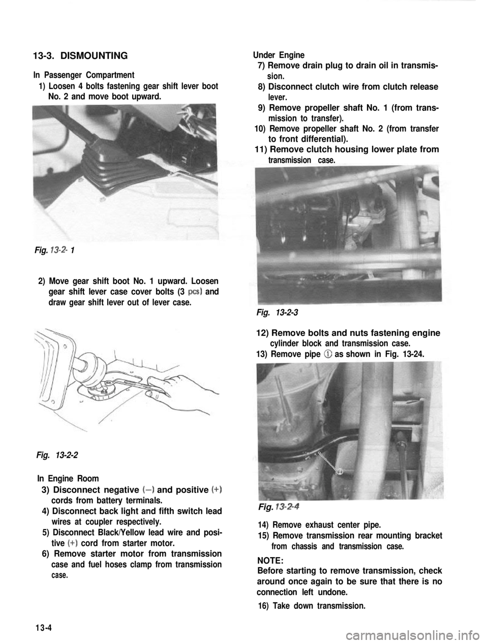
1) Loosen 4 bolts fastening gear shift lever boot
No. 2 and move boot upward.
Fig.
13-2- 1 Under Engine
7) Remove drain plug to drain oil in transmis-
sion.
8) Disconnect clutch wire from clutch release
lever.
9) Remove propeller shaft No. 1 (from trans-
mission to transfer).
10) Remove propeller shaft No. 2 (from transfer
to front differential).
11) Remove clutch housing lower plate from
transmission case.
2) Move gear shift boot No. 1 upward. Loosen
gear shift lever case cover bolts (3
PCS) and
draw gear shift lever out of lever case.
Fig. 13-2-3
Fig. 13-2-2 In Engine Room
3) Disconnect negative (-) and positive (+)
cords from battery terminals.
4) Disconnect back light and fifth switch lead
wires at coupler respectively.
5) Disconnect Black/Yellow lead wire and posi- tive
(+) cord from starter motor.
6) Remove starter motor from transmission
case and fuel hoses clamp from transmission
case.
12) Remove bolts and nuts fastening engine
cylinder block and transmission case.
13) Remove pipe (iJ as shown in Fig. 13-24.
Fig. 13-2-4
14) Remove exhaust center pipe.
15) Remove transmission rear mounting bracket
from chassis and transmission case.
NOTE:
Before starting to remove transmission, check
around once again to be sure that there is no
connection left undone.
16) Take down transmission.
13-4
Page 274 of 962
Input Shaft
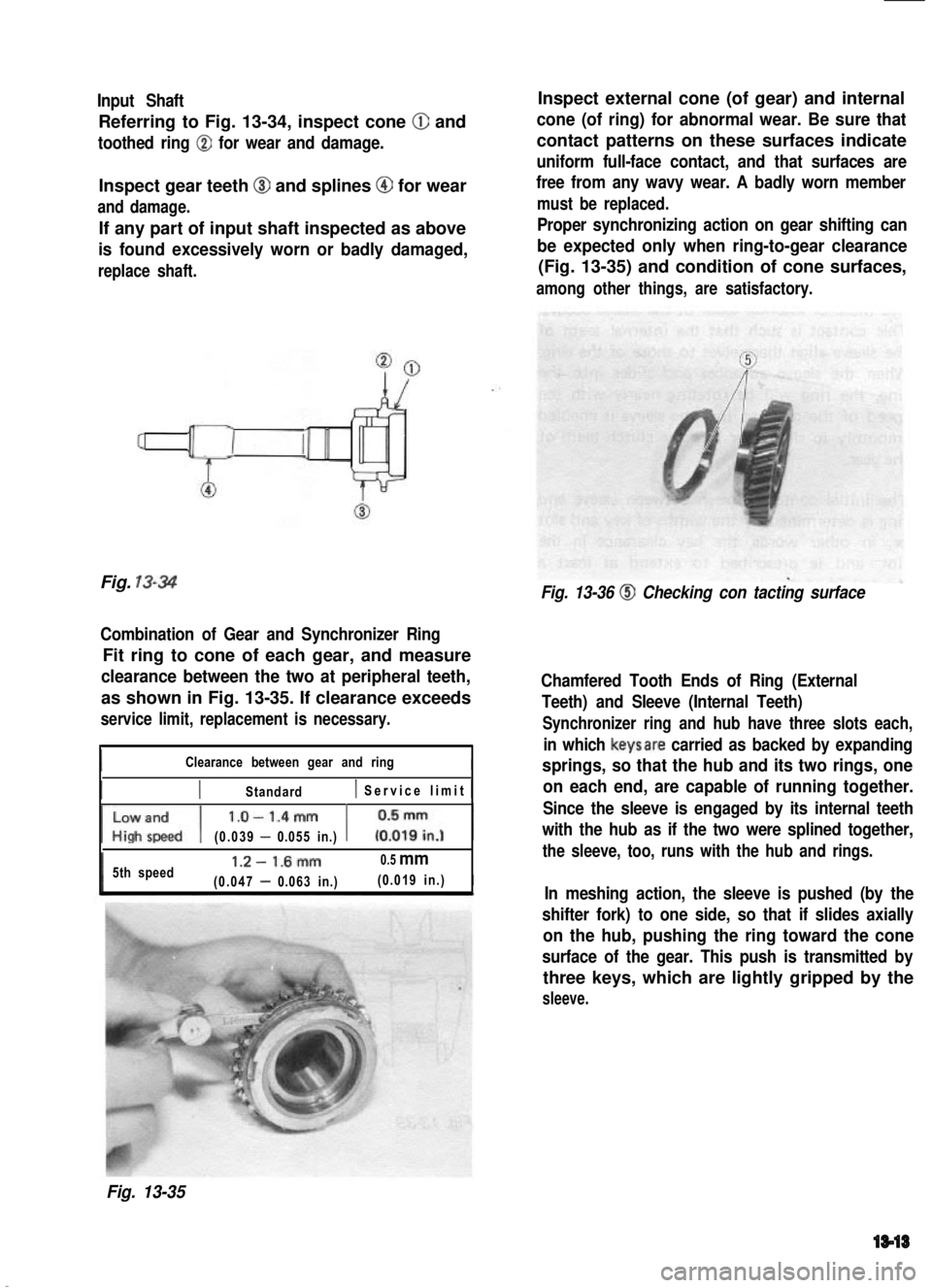
Referring to Fig. 13-34, inspect cone @ and
toothed ring @ for wear and damage.
Inspect gear teeth @I and splines @ for wear
and damage.
If any part of input shaft inspected as above
is found excessively worn or badly damaged,
replace shaft.
Inspect external cone (of gear) and internal
cone (of ring) for abnormal wear. Be sure that
contact patterns on these surfaces indicate
uniform full-face contact, and that surfaces are
free from any wavy wear. A badly worn member
must be replaced.
Proper synchronizing action on gear shifting can
be expected only when ring-to-gear clearance
(Fig. 13-35) and condition of cone surfaces,
among other things, are satisfactory.
Fig. 13-34
Combination of Gear and Synchronizer Ring
Fit ring to cone of each gear, and measure
clearance between the two at peripheral teeth,
as shown in Fig. 13-35. If clearance exceeds
service limit, replacement is necessary.
IClearance between gear and ringI
IIStandard( Service limit 1
~fJ l.O-1.4mm 1 iI;n.j 1
(0.039 - 0.055 in.)
5th speed1.2- 1.6mm0.5 mm
(0.047 - 0.063 in.)(0.019 in.)I
Fig. 13-36 @I Checking con tacting surface
Chamfered Tooth Ends of Ring (External
Teeth) and Sleeve (Internal Teeth)
Synchronizer ring and hub have three slots each,
in which keysare carried as backed by expanding
springs, so that the hub and its two rings, one
on each end, are capable of running together.
Since the sleeve is engaged by its internal teeth
with the hub as if the two were splined together,
the sleeve, too, runs with the hub and rings.
In meshing action, the sleeve is pushed (by the
shifter fork) to one side, so that if slides axially
on the hub, pushing the ring toward the cone
surface of the gear. This push is transmitted by
three keys, which are lightly gripped by the
sleeve.
Fig. 13-35
13-13
Page 292 of 962

14-4. TRANSFER SERVICES NOT REQUIRING TRANSFER REMOVAL
Following parts or components do not require transfer removal to receive services (replacement, inspec-
tion) :
Part or ComponentNature of Service
1. Universal-joint yoke flangesReplacement or inspection
2. Front drive shift shaft forkReplacement or inspectionI
3. Transfer output front shaft oil seal
4. Transfer output front shaft bearing
5. Transfer output front shaft
Replacement or inspection
Replacement
Replacement
6. Transfer front caseReplacement
7. Front drive clutch hubReplacement or inspection
8. Front drive clutch sleeveReplacement or inspection
9. Transfer input shaft oil sealReplacement
10. 4WD indicator light switchReplacement or inspection
11. Speedometer driven gearReplacement or inspection
12. Gear shift control leverReplacement or inspection
13. Gear shift control boot No. 1, No. 2Replacement
14. Gear shift control lever spring seatReplacement or inspection.
14-5
Page 295 of 962
14-6. DISASSEMBLY
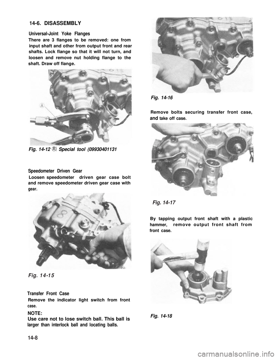
Universal-Joint Yoke Flanges
There are 3 flanges to be removed: one from
input shaft and other from output front and rear
shafts. Lock flange so that it will not turn, and
loosen and remove nut holding flange to the
shaft. Draw off flange.
Fig. 14-12 @ Special tool (09930401131
Speedometer Driven Gear
Loosen speedometerdriven gear case bolt
and remove speedometer driven gear case with
gear.
Transfer Front Case
Remove the indicator light switch from front
case.
NOTE:
Use care not to lose switch ball. This ball is
larger than interlock ball and locating balls.
Fig. 14-16
Remove bolts securing transfer front case,
and take off case.
By tapping output front shaft with a plastic
hammer,remove output front shaft from
front case.
Fig. 14-18
Fig. 14-15
14-8
Fig. 14-17
Page 320 of 962
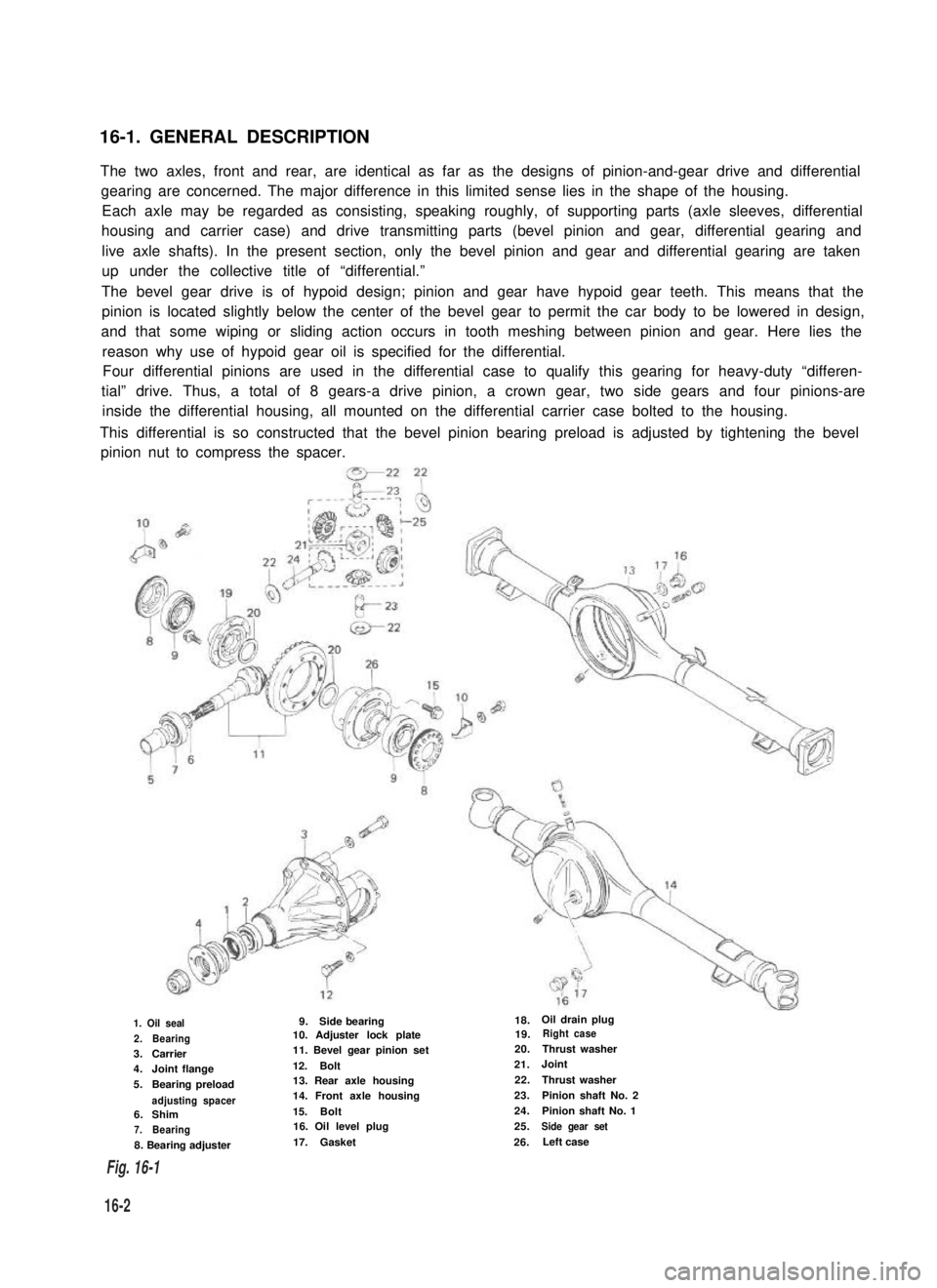
16-1. GENERAL DESCRIPTION
The two axles, front and rear, are identical as far as the designs of pinion-and-gear drive and differential
gearing are concerned. The major difference in this limited sense lies in the shape of the housing.
Each axle may be regarded as consisting, speaking roughly, of supporting parts (axle sleeves, differential
housing and carrier case) and drive transmitting parts (bevel pinion and gear, differential gearing and
live axle shafts). In the present section, only the bevel pinion and gear and differential gearing are taken
up under the collective title of “differential.”
The bevel gear drive is of hypoid design; pinion and gear have hypoid gear teeth. This means that the
pinion is located slightly below the center of the bevel gear to permit the car body to be lowered in design,
and that some wiping or sliding action occurs in tooth meshing between pinion and gear. Here lies the
reason why use of hypoid gear oil is specified for the differential.
Four differential pinions are used in the differential case to qualify this gearing for heavy-duty “differen-
tial” drive. Thus, a total of 8 gears-a drive pinion, a crown gear, two side gears and four pinions-are
inside the differential housing, all mounted on the differential carrier case bolted to the housing.
This differential is so constructed that the bevel pinion bearing preload is adjusted by tightening the bevel
pinion nut to compress the spacer.
1. Oil seal
2.Bearing3.Carrier4.Joint flange
5.Bearing preload
adjusting spacer6.Shim7.Bearing
8. Bearing adjuster
9.Side bearing10. Adjuster lock plate11. Bevel gear pinion set
12.Bolt13. Rear axle housing14. Front axle housing
15.Bolt16. Oil level plug
17.Gasket
18.Oil drain plug19.Right case
20.Thrust washer
21.Joint
22.Thrust washer
23.Pinion shaft No. 2
24.Pinion shaft No. 1
25.Side gear set
26.Left case
16-2
Fig. 16-1