Page 262 of 962

SECTION 13
TRANSMISSION
CONTENTS
13-l. GENERAL DESCRIPTION..................................13-1
TRANSMISSION GEAR RATIO..............................13-3
13-3. DISMOUNTING...........................................13-4
DISASSEMBLY............................................13-5
13-5. INSPECTION OF COMPONENTS............................13-12
13-6. IMPORTANT STEPS IN INSTALLATION.....................13-15
13-7. MAINTENANCE SERVICES................................13-25
13-8. RECOMMENDED TORQUE SPECIFICATION.................. 13-26
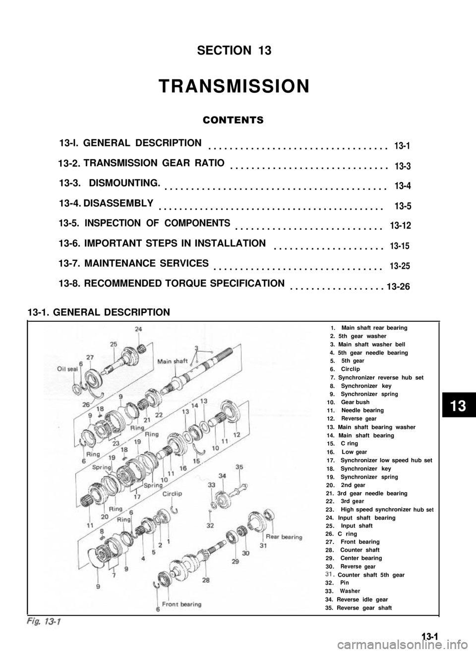
13-1. GENERAL DESCRIPTION
241.Main shaft rear bearing
2. 5th gear washer
3. Main shaft washer bell
4. 5th gear needle bearing
Oil sealfiMain shi5.5thgear
6.ICirclip
7. Synchronizer reverse hub set
8.Synchronizer key
9.Synchronizerspring
10.Gear bush
11.Needle bearing
12.Reversegear
13. Main shaft bearing washer
14. Main shaft bearing15.C ring
16.Lowgear
17.Synchronizer low speed hub set
18.Synchronizerkey
19.Synchronizerspring
20.2ndgear
F21. 3rd gear needle bearing22.3rdgear
23.hub
I
1High speed synchronizerset
I
24. Input shaft bearing25.Input shaft
i ’
IL’
ear bearing26. C ring27.AFront bearing
28.Counter shaft
429.Center bearing
930.ReversegearI i31. Counter shaft 5th gear
932.Pin
33.Washer
34. Reverse idle gear
35. Reverse gear shaft
13-1
13-2.
13-4.
13
Page 264 of 962
Reverse gear shift fork
Reverse gear
Ii
5th gear
I
Counter shaft 5th gaar
Counter shaft reverse gear
r
Reverse idle gear
13-2. TRANSMISSION GEAR RATIO
Primary gear ratio35123-
IPrimary speed ratio
Gear ratio
Secondary ratios
Speed ratio
Overall speed reduction ratio
41/18
2.277
3.466
-1.521
LowSecondThirdFourthFifth
36/l53212529131-25144
2.4001.2800.935-0.568
3.6521.9471.4231.0000.864
13-3
Page 265 of 962

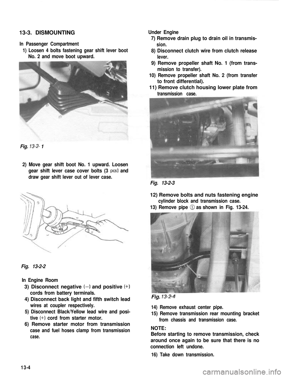
13-3. DISMOUNTINGIn Passenger Compartment
1) Loosen 4 bolts fastening gear shift lever boot
No. 2 and move boot upward.
Fig.
13-2- 1 Under Engine
7) Remove drain plug to drain oil in transmis-
sion.
8) Disconnect clutch wire from clutch release
lever.
9) Remove propeller shaft No. 1 (from trans-
mission to transfer).
10) Remove propeller shaft No. 2 (from transfer
to front differential).
11) Remove clutch housing lower plate from
transmission case.
2) Move gear shift boot No. 1 upward. Loosen
gear shift lever case cover bolts (3
PCS) and
draw gear shift lever out of lever case.
Fig. 13-2-3
Fig. 13-2-2 In Engine Room
3) Disconnect negative (-) and positive (+)
cords from battery terminals.
4) Disconnect back light and fifth switch lead
wires at coupler respectively.
5) Disconnect Black/Yellow lead wire and posi- tive
(+) cord from starter motor.
6) Remove starter motor from transmission
case and fuel hoses clamp from transmission
case.
12) Remove bolts and nuts fastening engine
cylinder block and transmission case.
13) Remove pipe (iJ as shown in Fig. 13-24.
Fig. 13-2-4
14) Remove exhaust center pipe.
15) Remove transmission rear mounting bracket
from chassis and transmission case.
NOTE:
Before starting to remove transmission, check
around once again to be sure that there is no
connection left undone.
16) Take down transmission.
13-4
Page 266 of 962
13-4. DISASSEMBLY
Replacing Clutch Release Shaft Bush
1) Remove clutch release bearing from input
shaft bearing retainer.
Fig. 13-3-Z
4) Take out the other bush, too.
Fig. 13-3
2) Remove a part of spring from clutch release
shaft lever.
Fig. 13-3-3
Fig. 13-3- 1
3) Remove clutch release shaft spring from
shaft. With special tool (A) applied in such a
position as shown in Fig. 13-3-2, tap the end
of special tool to take out bush and cap.
Clutch release bush remover (A) (09925
48210)
5) Precautions on bush reinstallation:
l Make sure to apply grease to inside of bushes.
l Drive in bushes to the same level as inside
surface of transmission case. Install cap and
oil seal securely after greasing oil seal lip.
Fig. 13-3-4
13-5
Page 267 of 962
Fig. 13-3-5
l After installing seal, caulk transmission case
against seal at two points.
Separating Upper Case from Lower Case
1) Remove clutch release bearing from trans-
mission input shaft.
Fig. 13-4-2
4) Remove bolts fastening upper and lower
cases together, separate the two, and take
out main shaft assembly. A steel bar, similar
in shape to screwdriver, may have to be
used to pry two cases apart, as shown. In
such a case, do not stick bar too far into
between two mating faces, or faces may
become damaged.
Fig. 13-4
2) Remove input shaft bearing retainer bolts
and pull out retainer by using 3 conventio-
nal 6 mm bolts.
Fig. 13-5
Fig. 13-4-l
3) Remove bolts securing extension
transmission case and reverse shift
0. Then take off extension case.
13-6
case to
rim bolt
Fig. 13-5 1
Page 279 of 962
Fig. 13-53
10) Install 3rd gear bearing, 3rd gear, high speed
synchronizer ring and hub/sleeve. When
installing hub, direct the side with larger
outer diameter boss to 3rd gear side. Then
fit circlip into groove in main shaft.
3rd earB
H’ub
Fig. 13-54
Fig. 13-55
11) Install synchronizer ring, needle bearing and
input shaft.
Fig. 13-56
Counter Shaft and Reverse Idle Gear
1) Drive counter shaft front bearing into lower
case. Then using plastic hammer, drive
counter shaft into front bearing a little.
In the above state, using bearing installer
(special tool), drive center bearing onto
counter shaft and into lower case.
Bearing installer (D) (09925-18010)
1. Center bearing
2. Counter shaft
Fig. 13-57
3. Transmission lower case
4. Wood stand
13-18
Page 283 of 962
Fig. 13-72Fig. 13:74 Main shaft and input shaft assembly
Transmission Lower Case and Upper Case
1) With counter shaft ass’y, reverse idle gear
and reverse gear shaft installed in lower
case, check to ensure that bearing stopper
rings @ are fitted in both sides of lower
case as shown below.
Also check for 2 knock pins 0.
Fig. 13-75
Fig. 13-73
2) Make sure that mating surfaces of both lower
and upper cases are clean.
3) Install main shaft and input shaft ass’y in
lower case.Fig. 13-76
13-22
Page 284 of 962
4) Uniformly apply sealant (SUZUKI BOND
NO. 1215, 99000-31110) to mating surface
of lower case.
Extension Case
1) Check to ensure that knock pins @ are
fitted.
Fig. 13-77Fig. 13-79
5) Install upper case to lower case by matching
3 shift forks with 3 grooves in synchronizer
sleeve on main shaft respectively.
Fig. 13-78 CiJ Shift forks
2)Apply grease (SUZUKI SUPER GREASE
A 99000-25010) to oil seal lip.
3) Clean surface of extension case to mate
with transmission case and uniformly apply
sealant (SUZUKI BOND No. 1215, 99000-
31110).
Fig. 13-806) Tighten case bolts to specification.
Tightening torque N.mkg-mlb-ftfor transmissioncase bolts18-281.8-2.813.5-20.0
4) Make sure that 3 shift shafts are in neutral
position as shown in Fig. 13-23.
5) Install extension case to transmission case.
6) Tighten case bolts to specification.
Tightening torque N.mkg-mlb-ftfor extension casebolts18-281.8-2.813.5-20.0
13-23