1987 SUZUKI GRAND VITARA transmission
[x] Cancel search: transmissionPage 163 of 962
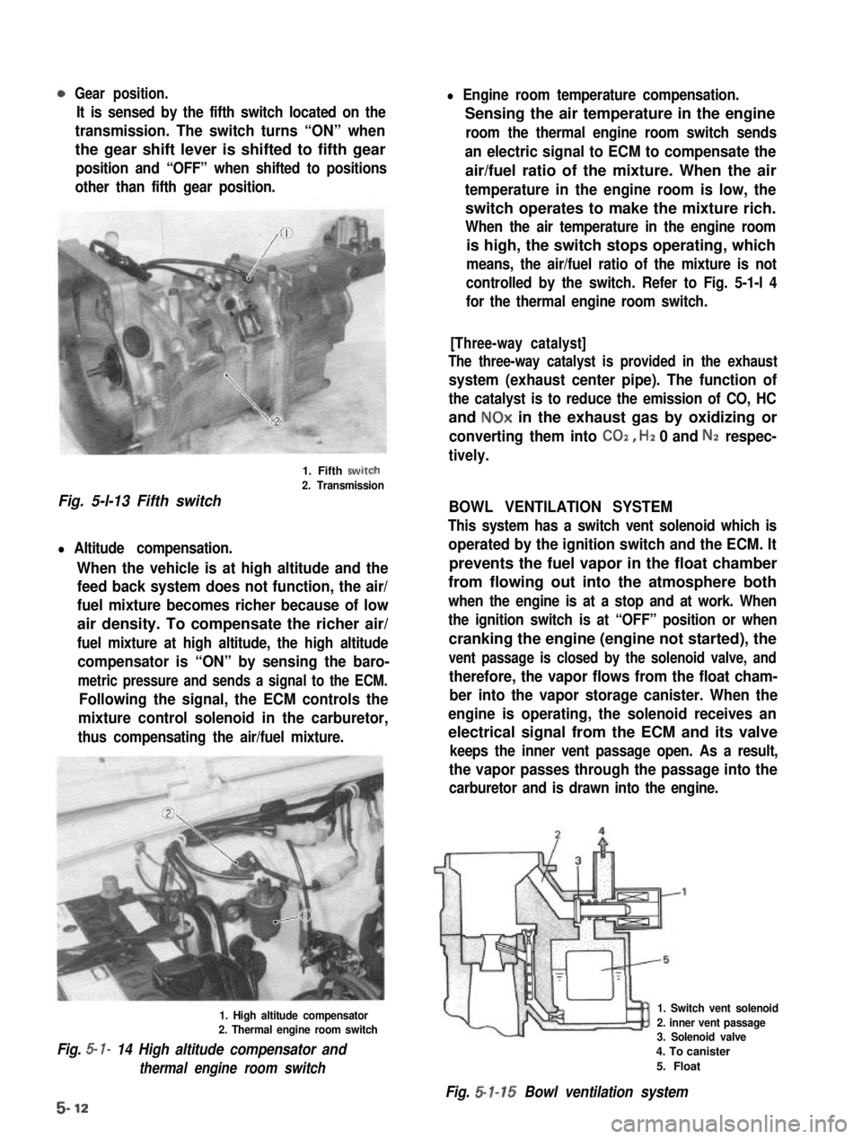
Gear position.
It is sensed by the fifth switch located on the
transmission. The switch turns “ON” when
the gear shift lever is shifted to fifth gear
position and “OFF” when shifted to positions
other than fifth gear position.
1. Fifth swirch
2. Transmission
Fig. 5-l-13 Fifth switch
l Altitude compensation.
When the vehicle is at high altitude and the
feed back system does not function, the air/
fuel mixture becomes richer because of low
air density. To compensate the richer air/
fuel mixture at high altitude, the high altitude
compensator is “ON” by sensing the baro-
metric pressure and sends a signal to the ECM.
Following the signal, the ECM controls the
mixture control solenoid in the carburetor,
thus compensating the air/fuel mixture.
1. High altitude compensator2. Thermal engine room switch
Fig. 5- I- 14 High altitude compensator and
thermal engine room switch
l Engine room temperature compensation.
Sensing the air temperature in the engine
room the thermal engine room switch sends
an electric signal to ECM to compensate the
air/fuel ratio of the mixture. When the air
temperature in the engine room is low, the
switch operates to make the mixture rich.
When the air temperature in the engine room
is high, the switch stops operating, which
means, the air/fuel ratio of the mixture is not
controlled by the switch. Refer to Fig. 5-1-l 4
for the thermal engine room switch.
[Three-way catalyst]
The three-way catalyst is provided in the exhaust
system (exhaust center pipe). The function of
the catalyst is to reduce the emission of CO, HC
and NOx in the exhaust gas by oxidizing or
converting them into CO2, Hz 0 and Nz respec-
tively.
BOWL VENTILATION SYSTEM
This system has a switch vent solenoid which is
operated by the ignition switch and the ECM. It
prevents the fuel vapor in the float chamber
from flowing out into the atmosphere both
when the engine is at a stop and at work. When
the ignition switch is at “OFF” position or when
cranking the engine (engine not started), the
vent passage is closed by the solenoid valve, and
therefore, the vapor flows from the float cham-
ber into the vapor storage canister. When the
engine is operating, the solenoid receives an
electrical signal from the ECM and its valve
keeps the inner vent passage open. As a result,
the vapor passes through the passage into the
carburetor and is drawn into the engine.
1. Switch vent solenoid
2. inner vent passage3. Solenoid valve
4. To canister
5. Float
Fig. 5-l-15 Bowl ventilation system
5-12
Page 219 of 962
Ignition Timing
Ignition timing10” BTDC at
800 * 50 r/min
1 Ignition orderIl-3-4-2I
When checking and adjusting ignition timing,
be sure to use timing light (09900-27301 or
09900-27311).
NOTE:
Prior to check and adjustment of ignition timing,
make sure that head lights, heater fan, rear
defogger (if equipped), and air conditioner (if
equipped) are “OFF”. If any one of these
systems is “ON”,idle up system operates and
engine idle speed will be out of the specification.
[Checking]
1. Remove rubber plug from timing check
window on the transmission case.
2. Start engine and warm it up to normal operat-
ing temperature.
3. After warming up, check to be sure that idle
speed is within specification. If idle speed is
out of specification, adjust it by turning
idle speed adjusting screw of carburetor.
4. Connect timing light to high tension cord of
No. 1 cylinder.
5. With engine running at specified idle speed,
direct the timing light to timing check win-
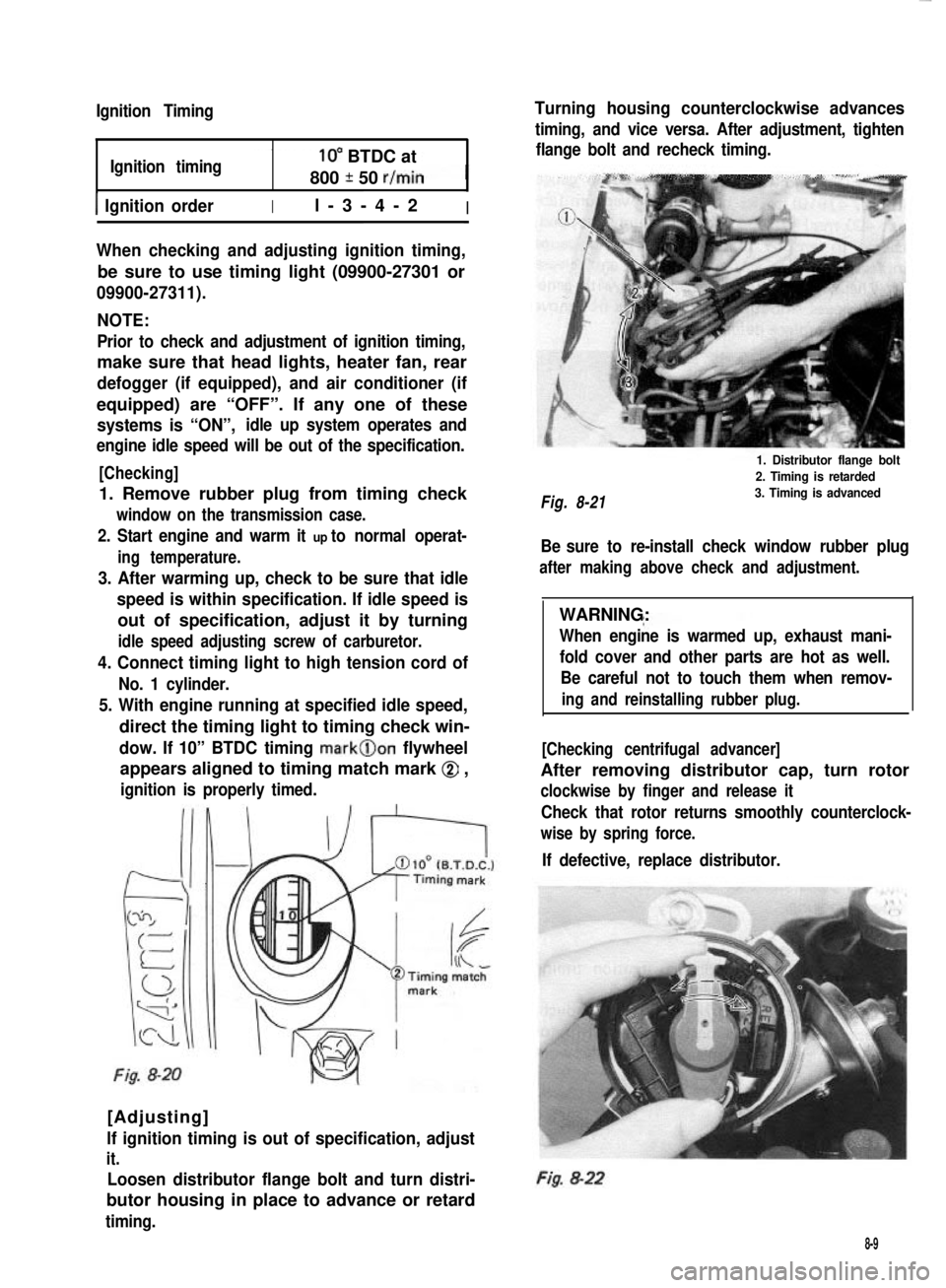
dow. If 10” BTDC timing mark@on flywheel
appears aligned to timing match mark @ ,
ignition is properly timed.
Fig. 8-20
[Adjusting]
lf ignition timing is out of specification, adjust
it.
Loosen distributor flange bolt and turn distri-
butor housing in place to advance or retard
timing.
Turning housing counterclockwise advances
timing, and vice versa. After adjustment, tighten
flange bolt and recheck timing.
Fig. 8-21
1. Distributor flange bolt
2. Timing is retarded
3. Timing is advanced
Be sure to re-install check window rubber plug
after making above check and adjustment.
WARNING:
When engine is warmed up, exhaust mani-
fold cover and other parts are hot as well.
Be careful not to touch them when remov-
ing and reinstalling rubber plug.
[Checking centrifugal advancer]
After removing distributor cap, turn rotor
clockwise by finger and release it
Check that rotor returns smoothly counterclock-
wise by spring force.
If defective, replace distributor.
Fig. 8-22
8-9
Page 244 of 962
![SUZUKI GRAND VITARA 1987 Service Repair Manual [Carrier and hold-down]
The battery carrier and hold-down clamp should
be clean and free from corrosion before instal-
ling the battery. The carrier should be in good
condition so that it will support SUZUKI GRAND VITARA 1987 Service Repair Manual [Carrier and hold-down]
The battery carrier and hold-down clamp should
be clean and free from corrosion before instal-
ling the battery. The carrier should be in good
condition so that it will support](/manual-img/20/57437/w960_57437-243.png)
[Carrier and hold-down]
The battery carrier and hold-down clamp should
be clean and free from corrosion before instal-
ling the battery. The carrier should be in good
condition so that it will support the battery
securely and keep it level.
Make certain there are no parts in carrier before
installing the battery.
To prevent the battery from shaking in its
carrier, the hold-down bolts should be tight but
not over tightened.
[Visual inspection]
Check for obvious damage, such as cracked or
broken case or cover, that could permit loss of
electrolyte. If obvious damage is noted, replace
the battery. Determine cause of damage and
correct as needed.
Check the battery terminal and cords for corro-
sion. If any, it should be cleaned.
[Built-in indicator]
This sealed battery has a built-in temperature
compensated indicator in the top of the battery.
This indicator is to be used with the following
diagnostic procedure. When observing the
indicator, make sure that the battery has a clean
top. A light may be needed in some poorly-lit
areas.
Under normal operation, two indications can
be seen
2
Clear
RedCHARGING
NECESSARY
Fig. lo-23
l Clear with Red Dot
This means the discharging battery. In this case,
charge the battery until the indicator will be
blue with red dot. The charging and electrical
systems should also be checked at this time. If
any defective is found, correct it. While charging
it, if the battery feels hot 52°C (125” F), or if
violent gassing or spewing of electrolyte through
the vent hole occurs, discontinue charging or
reduce charging rate.
[Jump starting in case of emergency with
auxiliary (booster) battery]
NOTE:
l Do not push or tow the vehicle to start.
Damage to the emission system and/or to
other parts of the vehicle may result.
8 Both booster and discharged battery should
be treated carefully when using jumper cables.
Follow the procedure outlined below, being
careful not to cause sparks:
CAUTION:
l Departure from these conditions or the
procedure below could result in: (1)
Serious personal injury (particularly to
eyes) or property damage from such
causes as battery explosion, battery acid,
or electrical burns; and/or (2) damage to
electronic components of either vehicle.
l Never expose battery to open flame or
electric spark-batteries generate a gas
which is flammable and explosive.
l Remove rings,watches,and other
jewelry. Wear approved eye protection.
l Do not allow battery fluid to contact
eyes, skin, fabrics, or painted surfaces -
fluid is a corrosive acid. Flush any con-
tacted area with water immediately and
thoroughly. Be careful that metal tools
or jumper cables do not contact the
positive battery terminal (or metal in
contact with it) and any other metal on
the car, because a short circuit could
occur. Batteries should always be kept
out of the reach of children.
1) Set parking brake and place transmission in
neutral. Turn off the ignition, turn off lights
and all other electrical loads.
2) Check electrolyte level. If level is below low
level line, replace battery.
NOTE:
When jump starting an engine with charging
equipment, be sure equipment used is 12volt
and negative ground. Do not use 24volt charging
equipment. Using each equipment can cause
serious damage to the electrical system or
electronic parts.
10-11
Page 247 of 962
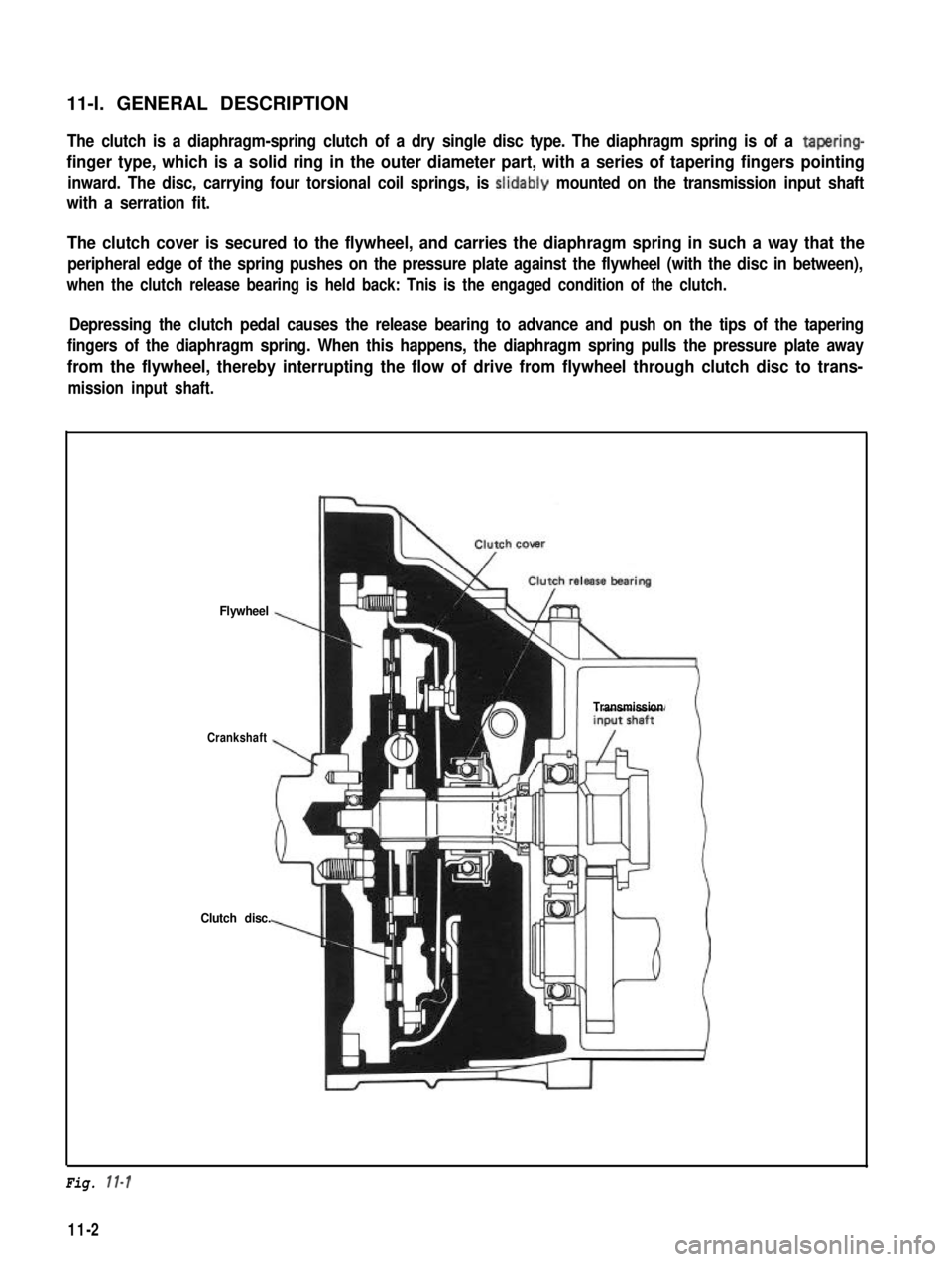
11-l. GENERAL DESCRIPTIONThe clutch is a diaphragm-spring clutch of a dry single disc type. The diaphragm spring is of a tapering-
finger type, which is a solid ring in the outer diameter part, with a series of tapering fingers pointing
inward. The disc, carrying four torsional coil springs, is slidably mounted on the transmission input shaft
with a serration fit.
The clutch cover is secured to the flywheel, and carries the diaphragm spring in such a way that the
peripheral edge of the spring pushes on the pressure plate against the flywheel (with the disc in between),
when the clutch release bearing is held back: Tnis is the engaged condition of the clutch.
Depressing the clutch pedal causes the release bearing to advance and push on the tips of the tapering
fingers of the diaphragm spring. When this happens, the diaphragm spring pulls the pressure plate away
from the flywheel, thereby interrupting the flow of drive from flywheel through clutch disc to trans-
mission input shaft.
Flywheel
Crankshaft
Clutch disc.
Transmission
Fig. 11-l
11-2
Page 249 of 962
11-2. REMOVALRemoval of clutch presupposes that the trans-
mission has been dismounted according to the
method outlined in SECTION 13 TRANS-
MISSION.
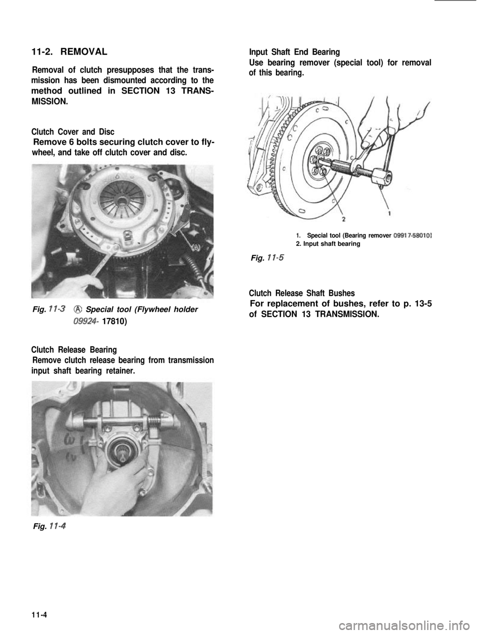
Clutch Cover and Disc
Remove 6 bolts securing clutch cover to fly-
wheel, and take off clutch cover and disc.
Fig. 1 l-3@ Special tool (Flywheel holder
09924- 17810)
Clutch Release Bearing Remove clutch release bearing from transmission
input shaft bearing retainer.
Input Shaft End Bearing
Use bearing remover (special tool) for removal
of this bearing.
1.Special tool (Bearing remover 09917-58010)
2. Input shaft bearing
Fig. 11-5
Clutch Release Shaft Bushes
For replacement of bushes, refer to p. 13-5
of SECTION 13 TRANSMISSION.
Fig. 11-4
11-4
Page 250 of 962
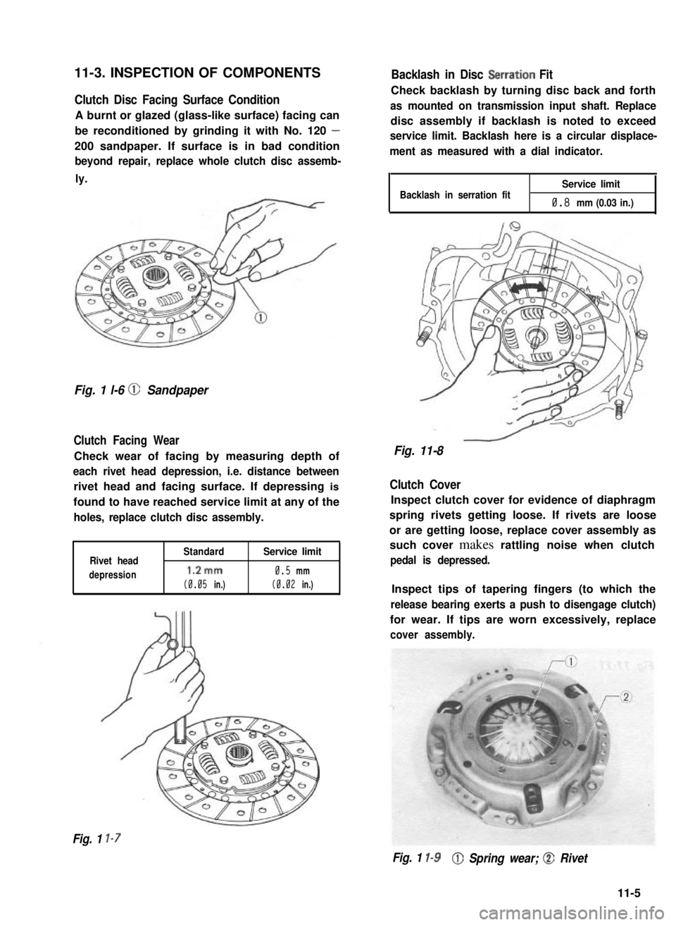
Clutch Disc Facing Surface Condition
A burnt or glazed (glass-like surface) facing can
be reconditioned by grinding it with No. 120 -
200 sandpaper. If surface is in bad condition
beyond repair, replace whole clutch disc assemb-
ly.
11-3. INSPECTION OF COMPONENTSBacklash in Disc Setration Fit
Check backlash by turning disc back and forth
as mounted on transmission input shaft. Replace
disc assembly if backlash is noted to exceed
service limit. Backlash here is a circular displace-
ment as measured with a dial indicator.
Fig. 1 l-6 @ Sandpaper
Clutch Facing Wear
Check wear of facing by measuring depth of
each rivet head depression, i.e. distance between
rivet head and facing surface. If depressing is
found to have reached service limit at any of the
holes, replace clutch disc assembly.
Rivet head
depression
Standard
1.2mm
(0.05 in.)
Service limit
0.5 mm
(0.02 in.)
Backlash in serration fitService limit
0.8 mm (0.03 in.)
Fig. 11-8
Clutch Cover
Inspect clutch cover for evidence of diaphragm
spring rivets getting loose. If rivets are loose
or are getting loose, replace cover assembly as
such cover makes rattling noise when clutch
pedal is depressed.
Inspect tips of tapering fingers (to which the
release bearing exerts a push to disengage clutch)
for wear. If tips are worn excessively, replace
cover assembly.
Fig. 1 l-7
Fig. 1 l-9@ Spring wear; @ Rivet
11-5
Page 253 of 962
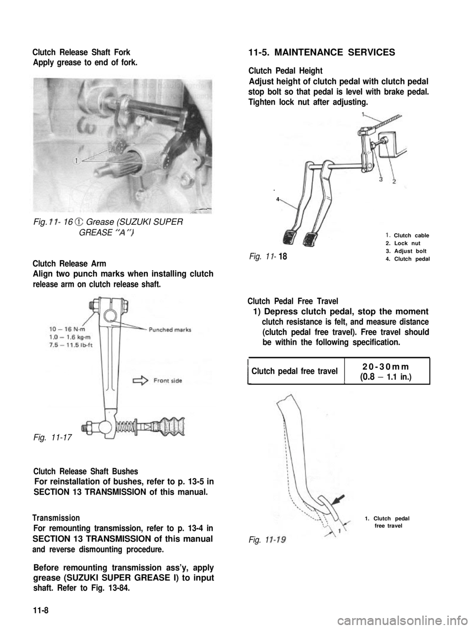
Clutch Release Shaft Fork
Apply grease to end of fork.
Fig. I l- 16 @ Grease (SUZUKI SUPER
GREASE “‘A “)
Clutch Release Arm
Align two punch marks when installing clutch
release arm on clutch release shaft.
Fig. 11-17
Clutch Release Shaft Bushes
For reinstallation of bushes, refer to p. 13-5 in
SECTION 13 TRANSMISSION of this manual.
Transmission
For remounting transmission, refer to p. 13-4 in
SECTION 13 TRANSMISSION of this manual
and reverse dismounting procedure.
11-5. MAINTENANCE SERVICES
Clutch Pedal Height
Adjust height of clutch pedal with clutch pedal
stop bolt so that pedal is level with brake pedal.
Tighten lock nut after adjusting.
.
4
I-
I- 18
1. Clutch cable2. Lock nut3. Adjust bolt4. Clutch pedalFig. 1
Clutch Pedal Free Travel
1) Depress clutch pedal, stop the moment
clutch resistance is felt, and measure distance
(clutch pedal free travel). Free travel should
be within the following specification.
!Clutch pedal free travel20-30mm
(0.8 - 1.1 in.)c
Fig. 1
1. Clutch pedalfree travel
Before remounting transmission ass’y, apply
grease (SUZUKI SUPER GREASE I) to input
shaft. Refer to Fig. 13-84.
11-8
Page 260 of 962
12-4. INSTALLATION
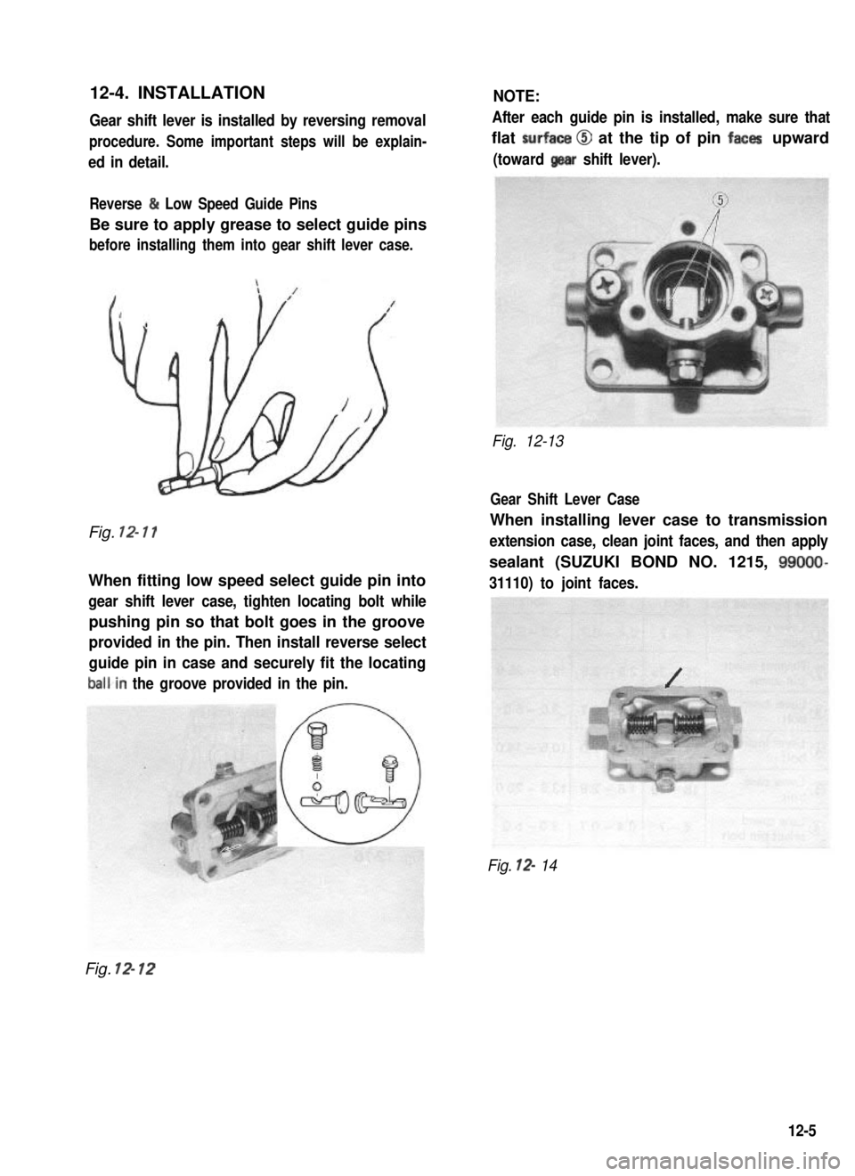
Gear shift lever is installed by reversing removal
procedure. Some important steps will be explain-
ed in detail.
NOTE:
After each guide pin is installed, make sure that
flat surfaca @I at the tip of pin faces upward
(toward gear shift lever).
Reverse & Low Speed Guide Pins
Be sure to apply grease to select guide pins
before installing them into gear shift lever case.
Fig. 12- 11
When fitting low speed select guide pin into
gear shift lever case, tighten locating bolt while
pushing pin so that bolt goes in the groove
provided in the pin. Then install reverse select
guide pin in case and securely fit the locating
balkin the groove provided in the pin.
Fig. 12-13
Gear Shift Lever Case
When installing lever case to transmission
extension case, clean joint faces, and then apply
sealant (SUZUKI BOND NO. 1215, 99009
31110) to joint faces.
Fig. 12- 14
Fig. 12- 12
12-5