Page 285 of 962

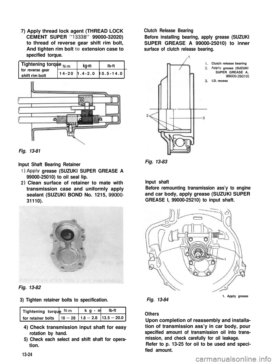
7) Apply thread lock agent (THREAD LOCK
CEMENT SUPER “1333B” 99000-32020)
to thread of reverse gear shift rim bolt,
And tighten rim bolt to. extension case to
specified torque.
Tightening torque ,,,”kg-mlb-ftfor reverse gear
shift rim bolt14-20 1.4-2.0 10.5-14.0
\
Fig. 13-81
Input Shaft Bearing Retainer
1
2
)Apply grease (SUZUKI SUPER GREASE A
99000-25010) to oil seal lip.
‘) Clean surface of retainer to mate with
transmission case and uniformly apply
sealant (SUZUKI BOND No. 1215, 99000-
31110).
Fig. 13-82
3) Tighten retainer bolts to specification.
h
Tightening torque N*mkg-mlb-ft
forretainerbolts18-281.8-2.813.5-20.0
4) Check transmission input shaft for easy
rotation by hand.
5) Check each select and shift shaft for opera-
tion.
Clutch Release Bearing
Before installing bearing, apply grease (SUZUKI
SUPER GREASE A 99000-25010) to inner
surface of clutch release bearing.
Fig. 13-83
Clutch release bearing
Apply grease (SUZUKISUPER GREASE A,99000-25010)I.D. recess
Input shaft
Before remounting transmission ass’y to engine
and car body, apply grease (SUZUKI SUPER
GREASE I, 99000-25210) to input shaft.
Fig. 13-841. Apply grease
Others
Upon completion of reassembly and installa-
tion of transmission ass’y in car body, pour
specified amount of transmission oil into trans-
mission, and check carefully for oil leakage.
Refer to p. 13-25 for oil to be used and speci-
fied amount.13-24
Page 286 of 962
13-7. MAINTENANCE SERVICES
Transmission Oil
Before changing oil, check for oil leakage first
and correct defects, if any. Fill specified new oil
in specified amount.
Oil capacity1.3 litres
(2.75/2.29 US/Imp. pt.)
IOil specificationGear oil, SAE 8OW-90,75W-80
or 75W-90I
It is. highly recommended to use SAE 75W-90.
gear oil.
For viscosity chart, refer to P. I-20.
Fig. 13-85
@ Oil filler plug
@ Oil drain plup@ Oil level plug
After filling transmission with oil, torque oil
filler and drain plugs to specification.
Tightening torque N.m
for oil drain andkg-mlb-ft
filler plug18-28 1.8-2.8 13.5-20.0
Tightening torque
for oil level pluglo-161.0-1. 7.5-11.5
NOTE:
Whenever car was hoisted for any other service
work than oil change, also be sure to check for
oil leakage.
When installing oil drain and filler plugs to
transmission case,aipply sealant (SUZUKI
BOND No.1215, 99000-31110) to thread part
of plug.
13-25
Page 287 of 962
13-8. RECOMMENDED TORQUE SPECIFICATION
Be sure to torque each bolt and nut according to specification given below, whenever loosened.
If specified torque for particular bolt or nut is not included in the list, refer to page O-13.
System
Gear shifting
control
TransmissionI
Fastening parts
8.Extension case bolt
13-25
Page 289 of 962

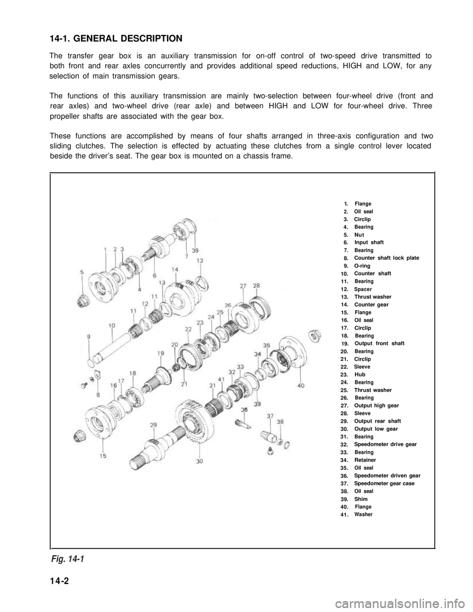
14-1. GENERAL DESCRIPTION
The transfer gear box is an auxiliary transmission for on-off control of two-speed drive transmitted to
both front and rear axles concurrently and provides additional speed reductions, HIGH and LOW, for any
selection of main transmission gears.
The functions of this auxiliary transmission are mainly two-selection between four-wheel drive (front and
rear axles) and two-wheel drive (rear axle) and between HIGH and LOW for four-wheel drive. Three
propeller shafts are associated with the gear box.
These functions are accomplished by means of four shafts arranged in three-axis configuration and two
sliding clutches. The selection is effected by actuating these clutches from a single control lever located
beside the driver’s seat. The gear box is mounted on a chassis frame.
1.Flange
2.Oil seal
3.Circlip
4.Bearing
5.Nut6.Input shaft
7.Bearing
8.Counter shaft lock plate
9.O-ring
10.Counter shaft
11.Bearing
12.Spacer
13.Thrust washer
14.Counter gear
15.Flange
16.Oil seal
17.Circlip
18.Bearing
19.Output front shaft
20.Bearing
21.Circlip
22.Sleeve
23.Hub
24.Bearing
25.Thrust washer
26.Bearing
27.Output high gear
28.Sleeve
29.Output rear shaft
30.Output low gear
31.Bearing
32.Speedometer drive gear
33.Bearing
34.Retainer
35.Oil seal
36.Speedometer driven gear
37.Speedometer gear case
38.Oil seal
39.Shim
40.Flange
41.Washer
Fig. 14- 1
14-2
Fig. 14-1
Page 312 of 962
151. GENERAL DESCRIPTION
These automobiles, covered in this manual are four-wheel drive machines and, as such, use three propeller
shafts designated as No. 1, No. 2 and No. 3.
No, 1 propeller shaft transmits drive from the transmission to the transfer gear box. No. 2 shaft and No. 3
shaft extend from the transfer gear box, the former driving the front axle and the latter the rear axle.
The cross spider in each universal joint is fitted with four needle roller bearings.
From
TQ transfer
transmission casaTo transfar casa
Propeller shaft No. 2
To rear differential
To front differential
To transfer case
15-2
Fig. 15-1
Page 313 of 962

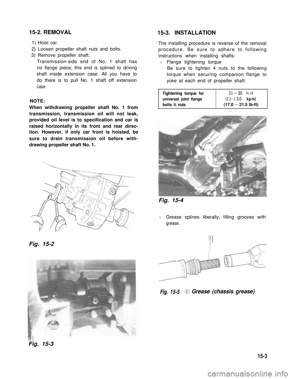
15-2. REMOVAL15-3. INSTALLATION
1) Hoist car.
2) Loosen propeller shaft nuts and bolts.
3) Remove propeller shaft.
Transmission-side end of No. 1 shaft has
no flange piece; this end is splined to driving
shaft inside extension case. All you have to
do there is to pull No. 1 shaft off extension
case.
NOTE:
When withdrawing propeller shaft No. 1 from
transmission, transmission oil will not leak,
provided oil level is to specification and car is
raised horizontally in its front and rear direc-
tion. However, if only car front is hoisted, be
sure to drain transmission oil before with-
drawing propeller shaft No. 1.
Fig. 15-2
The installing procedure is reverse of the removal
procedure. Be sure to adhere to following
instructions when installing shafts:
l Flange tightening torque
Be sure to tighten 4 nuts to the following
torque when securing companion flange to
yoke at each end of propeller shaft:
Tightening torque for
universal joint flange
bolts & nuts
23- 30 N.m
(2.3- 3.0 kg-m)
(17.0 - 21.5 lb-ft)
Fig. 15-4
l Grease splines liberally, filling grooves with
grease.
Q
Fig. 15-5@ Grease (chassis grease)
f&,a.
Fig. 15-3
15-3
Page 314 of 962

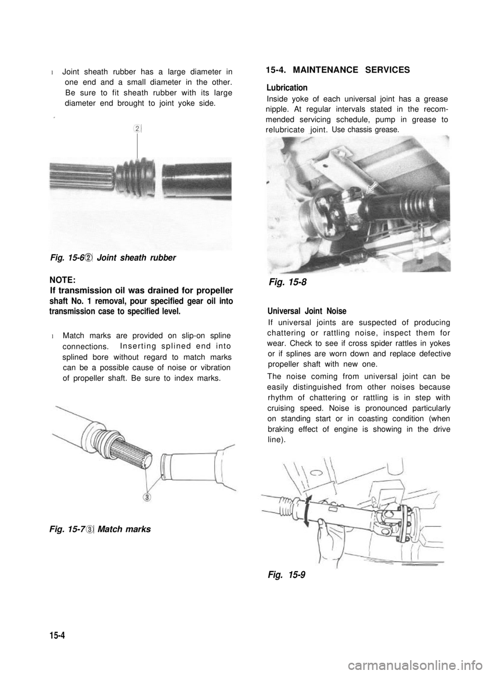
l Joint sheath rubber has a large diameter in
one end and a small diameter in the other.
Be sure to fit sheath rubber with its large
diameter end brought to joint yoke side.
.
cc
Fig. 15-6 @I Joint sheath rubber
NOTE:
If transmission oil was drained for propeller
shaft No. 1 removal, pour specified gear oil into
transmission case to specified level.
l Match marks are provided on slip-on spline
connections.Inserting splined end into
splined bore without regard to match marks
can be a possible cause of noise or vibration
of propeller shaft. Be sure to index marks.
Fig. 15-7 @I Match marks
15-4. MAINTENANCE SERVICES
Lubrication
Inside yoke of each universal joint has a grease
nipple. At regular intervals stated in the recom-
mended servicing schedule, pump in grease to
relubricate joint.Use chassis grease.
Fig. 15-8
Universal Joint Noise
If universal joints are suspected of producing
chattering or rattling noise, inspect them for
wear. Check to see if cross spider rattles in yokes
or if splines are worn down and replace defective
propeller shaft with new one.
The noise coming from universal joint can be
easily distinguished from other noises because
rhythm of chattering or rattling is in step with
cruising speed. Noise is pronounced particularly
on standing start or in coasting condition (when
braking effect of engine is showing in the drive
line).
Fig. 15-9
15-4
Page 471 of 962
ModelsConvertible/Hardtop ITEM
Tail/Brake light
Side marker light
12V, 3132 cp
12V, 3.8W
License plate light12V,4cp
Back-up light12V32cp
Interior light12v, 5wIMeter pilot light12V,1.4W
Main fuse
Fuse box
POWER TRANSMISSION
Clutch type
Transmission type
Final reduction ratio
0.5 mm2 (fusible link)
1 O/l Of 1 O/l 0/10/1 5/15/l 5/15/l 5/l 0/5/5/5A
Dry, single disc
5-forward all synchromesh, 1 reverse
3.727
Gear ratios
Transfer gear
ratios
Overall reduction ratios:
low3.652
2nd1.947
3rd1.423
4th
1 0.864
reverse1 3.466Ilow range
high range
2.268
1.409
Ilow1 30.8691
Low range
2nd16.457
3rd12.028
4th8.452
t5th7.303I
reverse29.297
low19.177
2nd10.224
3rd7.472
I
-.I4th5.251._..
5th
reverse
4.537
18.201
High range
22-2