Page 1063 of 1865
ASSEMBLY 7B
ASSEMBLY-STEP 2
Torque Specifications
12—10 N-m (1.2—1.8 m-kg, 8.7—130 ft-lb)
8—11 N-m (80—110 cm-kg, 68—95 In-lb)
41—55 N-m (4.2—5.6 m-kg, 30—41 ft-lb) 11—14 N-m (1.1—1.4 m-kg, 8—10 ft-lb)
86U07B-379
7B—197
Page 1065 of 1865
ASSEMBLY 7B
2. Install the parking assist lever and snap ring.
86U07B-382
86U07B-383
86U07B-384
3. Install the actuator support.
Tightening torque:
11—14 Nm (1.1—1.4 m-kg, 8.0—10 ft-lb)
4. Install the manual shaft and manual plate.
(1) Install the manual plate, spacer, washer, and
nut.
(2) Tighten the nut to specified torque.
Tightening torque:
41—55 Nm (4.2—5.6 m-kg, 30—41 ft-lb)
(3) Install the bracket.
Tightening torque:
8—11 N-m (80—110 cm-kg, 69—95 in-lb)
86U07B-385
7B-199
Page 1066 of 1865
7B ASSEMBLY
(4) Install the detent ball, spring, washer and plug;
then tighten the plug.
Tightening torque:
12—18
N
m (1.2—1.8 m-kg, 8.7—13 ft-lb)
86U07B-386
Install the low and reverse brake piston.
(1) Apply ATF to the inner and outer seals, and
install them to the low and reverse brake piston.
(2) Face the outer seal lip toward the inside by
gently rolling it down around the circumference
for easier installation into the case.
(3) Install the low and reverse brake piston by
pushing evenly around the circumference, be-
ing careful not to damage the outer seal.
86U07B-388
(4) Install the spring and retainer assembly.
86U07B-389
7B-200
Page 1067 of 1865

ASSEMBLY 7B
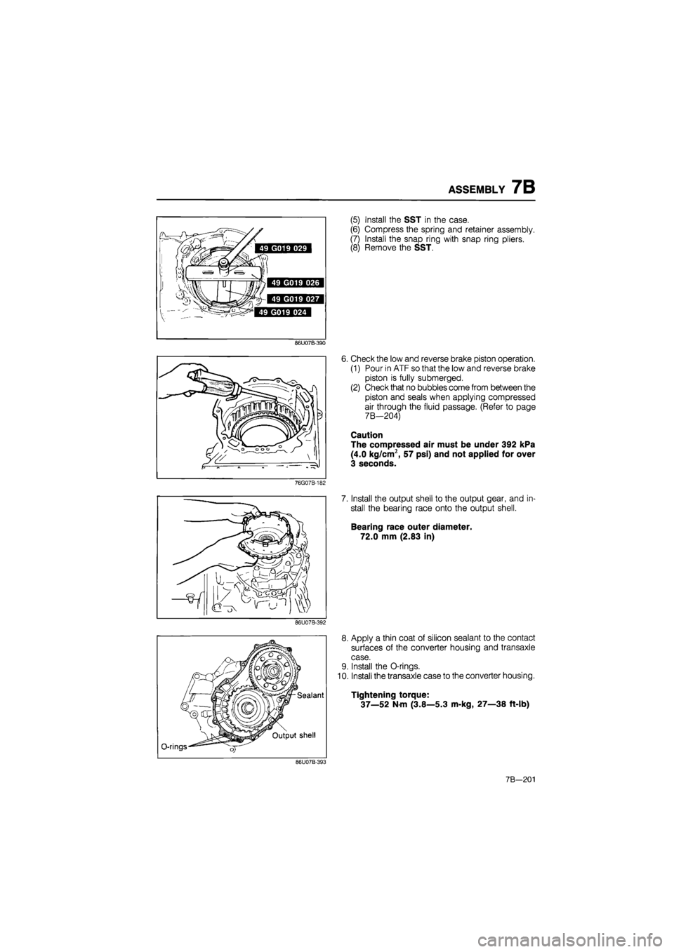
86U07B-390
76G07B-182
86U07B-392
O-rings
Sealant
Output shell
(5) Install the SST in the case.
(6) Compress the spring and retainer assembly.
(7) Install the snap ring with snap ring pliers.
(8) Remove the SST.
6. Check the low and reverse brake piston operation.
(1) Pour in ATF so that the low and reverse brake
piston is fully submerged.
(2) Check that no bubbles come from between the
piston and seals when applying compressed
air through the fluid passage. (Refer to page
7B—204)
Caution
The compressed air must be under 392 kPa
(4.0 kg/cm2, 57 psi) and not applied for over
3 seconds.
7. Install the output shell to the output gear, and in-
stall the bearing race onto the output shell.
Bearing race outer diameter.
72.0 mm (2.83 in)
8. Apply a thin coat of silicon sealant to the contact
surfaces of the converter housing and transaxle
case.
9. Install the O-rings.
10. Install the transaxle case to the converter housing.
Tightening torque:
37—52
N
m (3.8—5.3 m-kg, 27—38 ft-lb)
86U07B-393
7B—201
Page 1074 of 1865
7B ASSEMBLY
ASSEMBLY-STEP 4
Torque Specifications
31—47 N-m (3.7—4.8 m-kg, 23—35 ft-lb)
. 29—39 N-m (3.0—4.0 m-kg, 22—29 ft-lb)
16—24 N m (1.6—2.4 m-kg, 12-17 ft-lb)
8—11 N-m (80—110 cm-kg, 69—95 In-lb)
19—26 N-m I.9—2.6 m-kg, 14—19 ft-lb)
SB—67 N-m (5.9—6.8 m-kg, 43—49 ft-lb)
— 19—26 N-m (1.9—2.6 m-kg, 14—19 ft-lb)
8—11 N-m (85—110 cm-kg, 74—95 in-lb)
8—11 N-m (80—110 cm-kg, 69-95 in-lb)
8—11 N-m (0.8—1.1 m-kg, 69—95 In-lb)
86U07B-417
7B-208
Page 1075 of 1865
ASSEMBLY 7B
86U07B-418
86U07B-419
76G07B-223
Procedure
1. Use the following procedure to adjust the total end
play and select a suitable bearing race.
(1) Set the thrust bearing onto the clutch assembly.
(2) Remove the previous race and gasket.
(3) Set the thickest bearing race 2.2 mm (0.087
in) onto the oil pump.
(4) Set the oil pump onto the clutch assembly.
(5) Measure clearance between the transaxle case
and oil pump.
(6) Select a suitable bearing race from the chart
below.
Clearance mm (in) Select this bearing race mm (in)
0.91-1.10 (0.036—0.043) 1.2 (0.047)
0.71-0.90 (0.028-0.035) 1.4 (0.055)
0.51-0.70 (0.020—0.027) 1.6 (0.063)
0.31-0.50 (0.012-0.019) 1.8 (0.071)
0.11-0.30 (0.004-0.011) 2.0 (0.078)
0-0.10 (0-0.003) 2.2 (0.087)
(7) Remove the oil pump.
(8) Place the selected bearing race and a new gas-
ket onto the oil pump.
(9) Install the oil pump onto the clutch assembly.
Tightening torque:
19—26 Nm (1.9—2.6 m-kg, 14—19 ft-lb)
86U07B-421
7B-209
Page 1076 of 1865
7B ASSEMBLY
2. Adjust the 2-4 brake band.
(1) Loosen the locknut and tighten the piston stem
to the specified torque.
Tightening torque:
9—11
N
m (90—110 cm-kg, 78—95 in-lb)
86U07B-422
(2) Loosen the piston stem 2 turns.
(3) Tighten the locknut to the specified torque.
Tightening torque:
25—39 N-m (2.5—4.0 m-kg, 18—29 tt-lb)
86U07B-423
Install the oil strainer along with a new O-ring to
the transaxle.
Tightening torque:
8—11 N-m (80—110 cm-kg, 69—95 in-lb)
86U07B-424
4. Install the oil pan along with a new gasket.
Tightening torque:
8—11 N-m (85—110 cm-kg, 74—95 in-lb)
Note
Install the magnets in the positions shown in
the illustration.
86U07B-425
7B—210
Page 1077 of 1865
ASSEMBLY 7B
5. Align the manual valve with the pin on the manual
plate, and install the control valve body into the
transaxle case.
Tightening torque:
11—15 Nm
(110—150 cm-kg, 95—130 in-lb)
86U07B-426
6. Install the solenoid connector and a new O-ring in
the transaxle case.
86U07B-427
7. Install a new O-ring on the bracket; then feed the
throttle cable through the transaxle case and con-
nect it to the throttle cam.
8. Install the throttle cable attaching bolts and bracket.
Tightening torque:
(§)8—11 Nm
(80—110 cm-kg, 69—95 in-lb)
(1)19—26
N
m
(1.9—2.6 m-kg, 14—19 ft-lb)
86U07B-428
9. Install the control valve body cover along with a
new gasket.
Tightening torque:
8—11
N
m (85—110 cm-kg, 74—95 in-lb)
86U07B-429
7 B—211