Page 1028 of 1865
7B INSPECTION AND PREAIR
83U07B-289
83U07B-290
83U07B-291
6. Install the N-R accumulator gasket and plate; then
tighten the plate.
Tightening torque:
6—8
N
m (66—80 cm-kg, 57—69 in-lb)
7. Apply ATF to the O-rings, and install them onto the
piston; then install the 1-2 accumulator piston and
1-2 accumulator springs.
8. Install the 1-2 accumulator gasket and plate; then
tighten the plate.
Tightening torque:
6—8 N-m (66—80 cm-kg, 57—69 in-lb)
9. Install the OD release spring, OD release valve,
stopper plug, and stopper pin.
10. Install the bypass spring, bypass valve, stopper
plug, and stopper pin.
11. Install the servo control spring, servo control valve,
stopper plug, and stopper pin.
83U07B-292
7B-162
Page 1032 of 1865

7B INSPECTION AND REPAIR
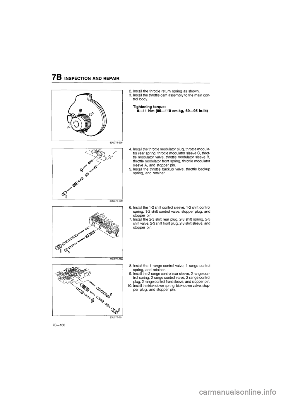
2. Install the throttle return spring as shown.
3. Install the throttle cam assembly to the main con-
trol body.
Tightening torque:
8—11 N-m (80—110 cm-kg, 69—95 in-lb)
83U07B-298
Install the throttle modulator plug, throttle modula-
tor rear spring, throttle modulator sleeve C, throt-
tle modulator valve, throttle modulator sleeve B,
throttle modulator front spring, throttle modulator
sleeve A, and stopper pin.
Install the throttle backup valve, throttle backup
spring, and retainer.
83U07B-299
6. Install the 1-2 shift control sleeve, 1-2 shift control
spring, 1-2 shift control valve, stopper plug, and
stopper pin.
7. Install the 2-3 shift rear plug, 2-3 shift spring, 2-3
shift valve, 2-3 shift front plug, 2-3 shift sleeve, and
stopper pin.
83U07B-300
8. Install the 1 range control valve, 1 range control
spring, and retainer.
9. Install the 2 range control rear sleeve, 2 range con-
trol spring, 2 range control valve, 2 range control
plug, 2 range control front sleeve, and stopper pin.
10. Install the kick-down spring, kick-down valve, stop-
per plug, and stopper pin.
7B-166
Page 1041 of 1865
INSPECTION AND REPAIR 7B
83U07B-326
83U07B-327
83U07B-328
O O CD O C"~>
\<~>C~>
">0
13. Install the front control body on the premain con-
trol body.
14. Loosely tighten the bolts and bracket.
Note
Match the bolt head letter as shown.
15. Install the control valve body mounting bolts as
shown for alignment.
16. Tighten the mounting bolts.
(1) Tighten the front control body.
Tightening torque:
6—8 N-m (66—80 cm-kg, 57—69 in-lb)
83U07B-329
7B—175
Page 1042 of 1865
7B INSPECTION AND REPAIR
(2) Tighten the rear control body.
Tightening torque:
6—8 N-m (66—80 cm-kg, 57—69 in-lb)
17. Install the lock-up solenoid valve along with new
O-ring and oil strainer.
Tightening torque:
6—8 N-m (66—80 cm-kg, 57—69 in-lb)
7B—176
83U07B-330
83U07B-331
Page 1049 of 1865
INSPECTION AND REPAIR 7B
Inspection
Check the following and replace any faulty parts.
1. Damaged or worn idle gear
2. Damaged or worn bearing
86U07B-340
Assembly
1. Press the bearing outer races in with the SST.
86U07B-341
86U07B-342
2. Install the idle gear bearing onto the idle shaft, then
install the idle gear, adjust shim, spacer, and
bearing.
3. Secure the idle shaft in a vise with the SST; then
tighten the locknut to the lower limit of the tighten-
ing torque.
Tightening torque:
128 N-m (13 m-kg, 94 ft-lb)
Note
Use the protective plates to prevent damage
to the SST.
86U07B-343
7B—183
Page 1050 of 1865

7B INSPECTION AND REPAIR
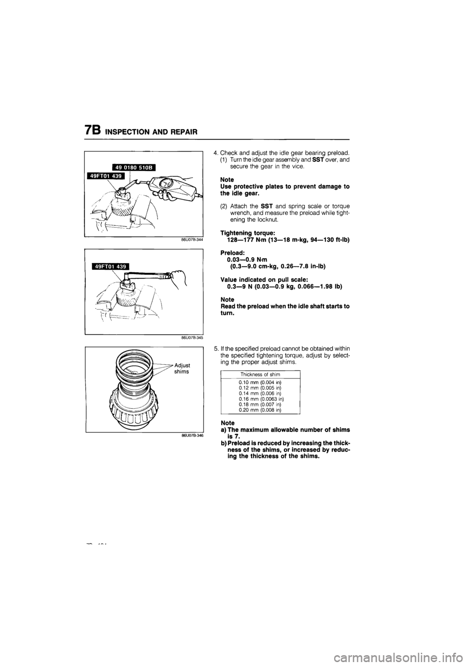
4. Check and adjust the idle gear bearing preload.
(1) Turn the idle gear assembly and SST over, and
secure the gear in the vice.
Note
Use protective plates to prevent damage to
the idle gear.
(2) Attach the SST and spring scale or torque
wrench, and measure the preload while tight-
ening the locknut.
Tightening torque:
128—177
N m
(13—18 m-kg, 94—130 ft-lb)
49FT01 439
Preload:
0.03—0.9 N-m
(0.3—9.0 cm-kg, 0.26—7.8 in-lb)
Value indicated on pull scale:
0.3—9 N (0.03—0.9 kg, 0.066—1.98 lb)
Note
Read the preload when the idle shaft starts to
turn.
86U07B-345
86U07B-346
5. If the specified preload cannot be obtained within
the specified tightening torque, adjust by select-
ing the proper adjust shims.
Thickness
of
shim
0.10 mm (0.004
in)
0.12
mm
(0.005
in)
0.14
mm
(0.006
in)
0.16
mm
(0.0063
in)
0.18 mm (0.007
in)
0.20 mm (0.008
in)
Note
a) The maximum allowable number of shims
is 7.
b) Preload is reduced by increasing the thick-
ness of the shims, or increased by reduc-
ing the thickness of the shims.
Page 1053 of 1865
ASSEMBLY 7B
ASSEMBLY
PRECAUTION
(1) The automatic transaxle consists of high-precision-finished parts, necessitating careful inspection
before assembly because even a small nick could cause fluid leakage or affect performance.
(2) Clean out oil holes and oil passages with compressed air, and check that there are no obstructions.
(3) Before assembly, apply ATF to each O-ring, seal ring, rotating part, and friction part.
(4) If the brake band or drive plates are replaced with new ones, first soak them in ATF for at least
2 hours before installing.
(5) Each seal gasket and O-ring must be replaced with a new one.
(6) Be sure to install all thrust bearings and races in the correct direction and position.
ASSEMBLY—STEP 1
Torque Specifications
83U07B-365
11—14 N-m (110—140 cm-kg, 95—122 in-lb) 6-9 N-m (60—90 cm-kg, 52—78 in-lb)
8—11 N-m (80—110 cm-kg, 69—95 In-lb)
19—26 N m (1.9—2.6 m-kg, 14—19 ft-lb)
83U07B-366
7B—187
Page 1054 of 1865
7B ASSEMBLY
Procedure
1. Adjust the preload of the output gear bearing and select the adjust shim(s) as described below.
Note To adjust the preload, use the SST shown below.
83U07B-367
83U07B-368
(1) Press the bearing cover in after aligning it with
guide bolts as shown.
Tightening torque: 11—14 N-m
(110—140 cm-kg, 95—122 in-lb)
(2) Install the converter housing onto the SST.
(3) Remove the bearing outer race and adjust
shims from the bearing housing. (Refer to page
7B—185)
(4) Mount the output gear assembly onto the con-
verter housing.
76G07B-171
7B-188