Page 2111 of 2389
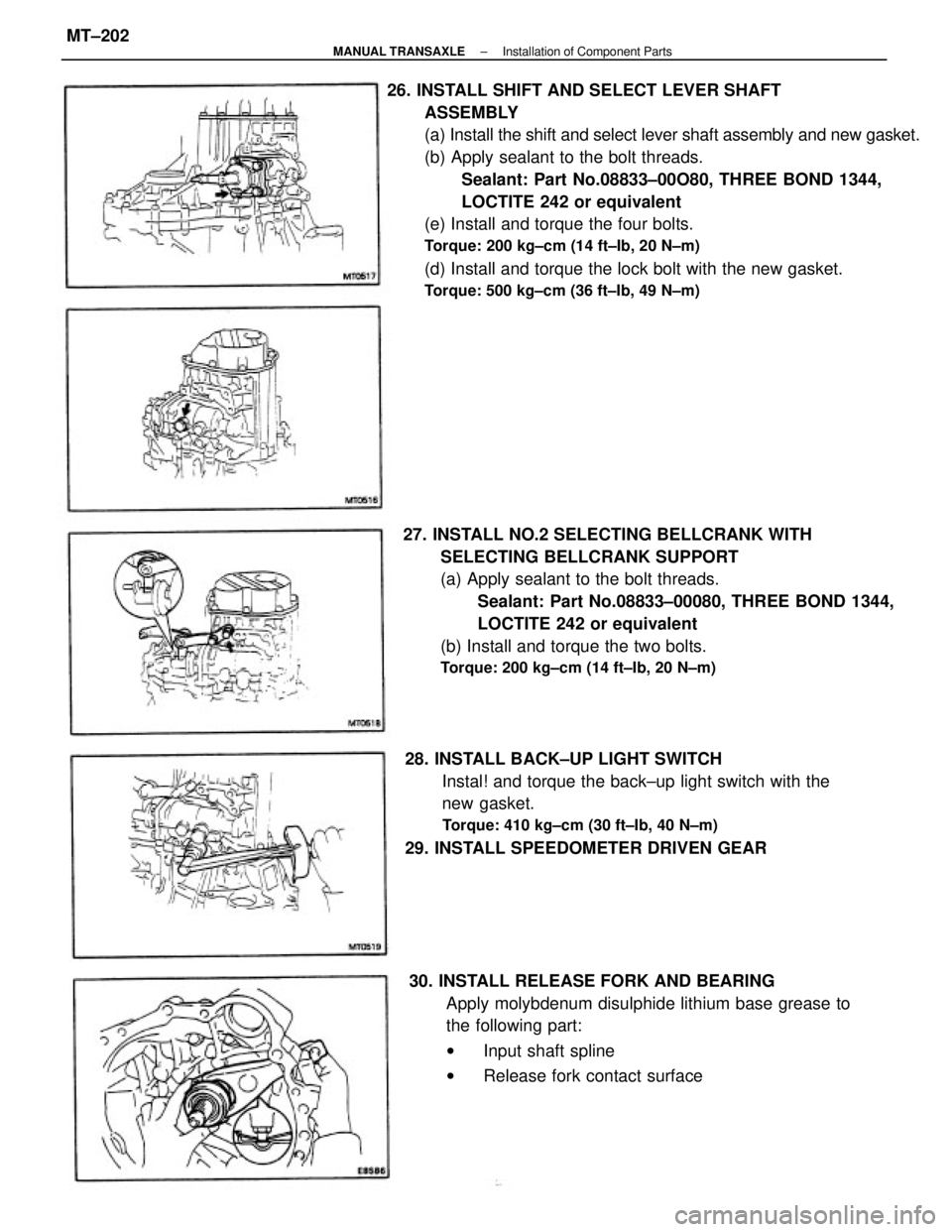
26. INSTALL SHIFT AND SELECT LEVER SHAFT
ASSEMBLY
(a) Install the shift and select lever shaft assembly and new gasket.
(b) Apply sealant to the bolt threads.
Sealant: Part No.08833±00O80, THREE BOND 1344,
LOCTITE 242 or equivalent
(e) Install and torque the four bolts.
Torque: 200 kg±cm (14 ft±Ib, 20 N±m)
(d) Install and torque the lock bolt with the new gasket.
Torque: 500 kg±cm (36 ft±Ib, 49 N±m)
27. INSTALL NO.2 SELECTING BELLCRANK WITH
SELECTING BELLCRANK SUPPORT
(a) Apply sealant to the bolt threads.
Sealant: Part No.08833±00080, THREE BOND 1344,
LOCTITE 242 or equivalent
(b) Install and torque the two bolts.
Torque: 200 kg±cm (14 ft±Ib, 20 N±m)
28. INSTALL BACK±UP LIGHT SWITCH
Instal! and torque the back±up light switch with the
new gasket.
Torque: 410 kg±cm (30 ft±Ib, 40 N±m)
29. INSTALL SPEEDOMETER DRIVEN GEAR
30. INSTALL RELEASE FORK AND BEARING
Apply molybdenum disulphide lithium base grease to
the following part:
wInput shaft spline
wRelease fork contact surface
± MANUAL TRANSAXLEInstallation of Component PartsMT±202
Page 2112 of 2389
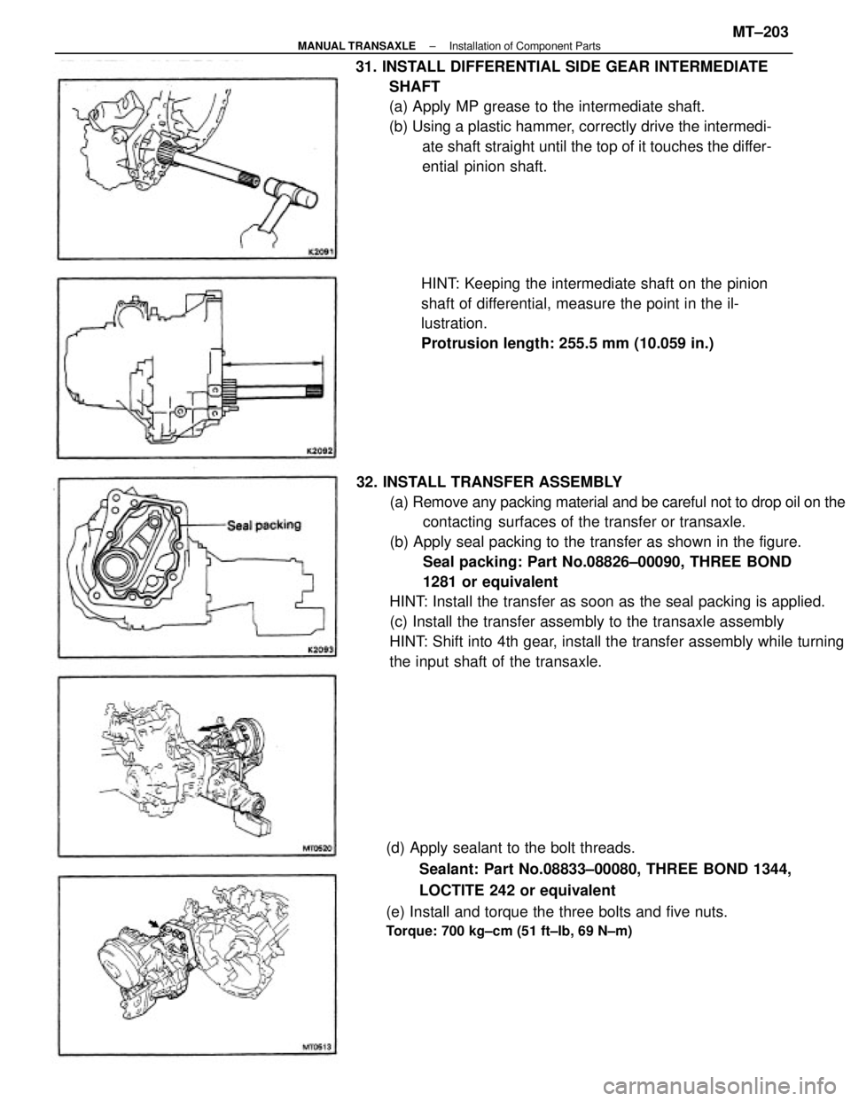
32. INSTALL TRANSFER ASSEMBLY
(a) Remove any packing material and be careful not to drop oil on the
contacting surfaces of the transfer or transaxle.
(b) Apply seal packing to the transfer as shown in the figure.
Seal packing: Part No.08826±00090, THREE BOND
1281 or equivalent
HINT: Install the transfer as soon as the seal packing is applied.
(c) Install the transfer assembly to the transaxle assembly
HINT: Shift into 4th gear, install the transfer assembly while turning
the input shaft of the transaxle. 31. INSTALL DIFFERENTIAL SIDE GEAR INTERMEDIATE
SHAFT
(a) Apply MP grease to the intermediate shaft.
(b) Using a plastic hammer, correctly drive the intermedi-
ate shaft straight until the top of it touches the differ-
ential pinion shaft.
(d) Apply sealant to the bolt threads.
Sealant: Part No.08833±00080, THREE BOND 1344,
LOCTITE 242 or equivalent
(e) Install and torque the three bolts and five nuts.
Torque: 700 kg±cm (51 ft±Ib, 69 N±m)
HINT: Keeping the intermediate shaft on the pinion
shaft of differential, measure the point in the il-
lustration.
Protrusion length: 255.5 mm (10.059 in.)
± MANUAL TRANSAXLEInstallation of Component PartsMT±203
Page 2120 of 2389
18. IF NECESSARY, REPLACE TRANSFER OIL TUBE
(a) Remove the bolt and oil tube.
(d) Install the oil tube.
(e) Install and torque the bolt.
Torque: 130 kg±cm (9 ft±Ib, 13 N±m)
(d) Using snap ring pliers, install the snap ring.
(b) Using a screwdriver, remove the cushion.
(c) Install anew cushion.
± MANUAL TRANSAXLEComponent Parts (Transfer Assembly E56F5)MT±175
Page 2125 of 2389
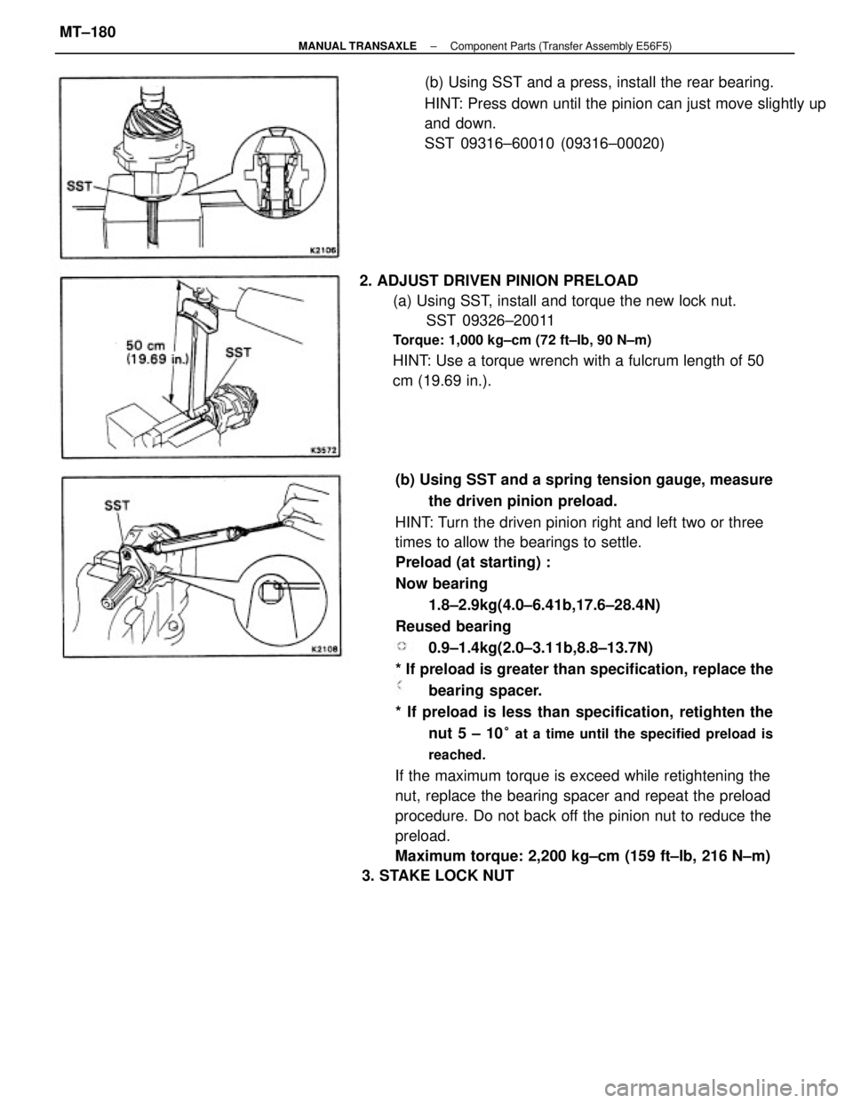
(b) Using SST and a spring tension gauge, measure
the driven pinion preload.
HINT: Turn the driven pinion right and left two or three
times to allow the bearings to settle.
Preload (at starting) :
Now bearing
1.8±2.9kg(4.0±6.41b,17.6±28.4N)
Reused bearing
0.9±1.4kg(2.0±3.1 1b,8.8±13.7N)
* If preload is greater than specification, replace the
bearing spacer.
* If preload is less than specification, retighten the
nut 5 ± 10
° at a time until the specified preload is
reached.
If the maximum torque is exceed while retightening the
nut, replace the bearing spacer and repeat the preload
procedure. Do not back off the pinion nut to reduce the
preload.
Maximum torque: 2,200 kg±cm (159 ft±Ib, 216 N±m)
3. STAKE LOCK NUT 2. ADJUST DRIVEN PINION PRELOAD
(a) Using SST, install and torque the new lock nut.
SST 09326±20011
Torque: 1,000 kg±cm (72 ft±Ib, 90 N±m)
HINT: Use a torque wrench with a fulcrum length of 50
cm (19.69 in.).(b) Using SST and a press, install the rear bearing.
HINT: Press down until the pinion can just move slightly up
and down.
SST 09316±60010 (09316±00020)
± MANUAL TRANSAXLEComponent Parts (Transfer Assembly E56F5)MT±180
Page 2127 of 2389
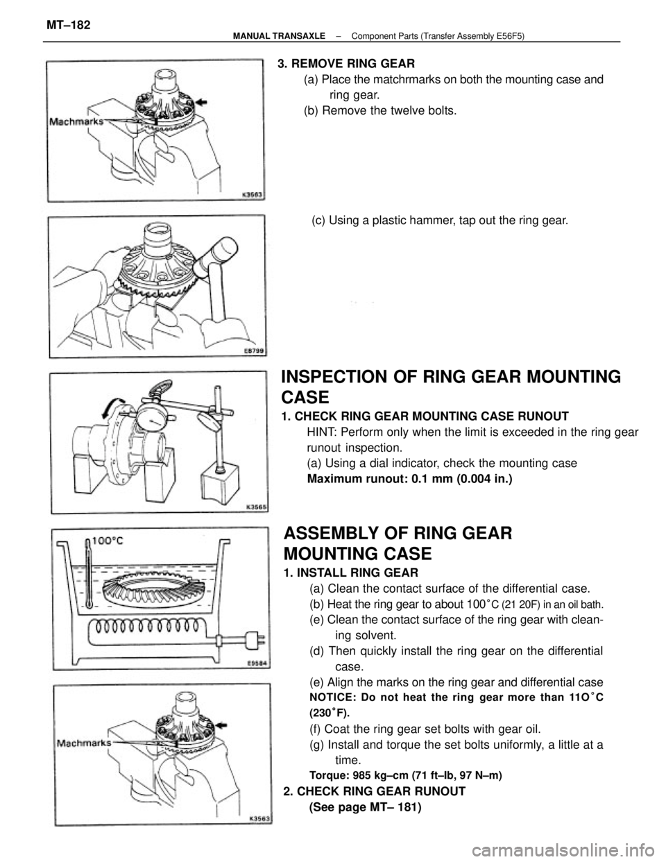
ASSEMBLY OF RING GEAR
MOUNTING CASE
1. INSTALL RING GEAR
(a) Clean the contact surface of the differential case.
(b) Heat the ring gear to about 100
°C (21 20F) in an oil bath.
(e) Clean the contact surface of the ring gear with clean-
ing solvent.
(d) Then quickly install the ring gear on the differential
case.
(e) Align the marks on the ring gear and differential case
NOTICE: Do not heat the ring gear more than 11O°C
(230°F).
(f) Coat the ring gear set bolts with gear oil.
(g) Install and torque the set bolts uniformly, a little at a
time.
Torque: 985 kg±cm (71 ft±Ib, 97 N±m)
2. CHECK RING GEAR RUNOUT
(See page MT± 181)
INSPECTION OF RING GEAR MOUNTING
CASE
1. CHECK RING GEAR MOUNTING CASE RUNOUT
HINT: Perform only when the limit is exceeded in the ring gear
runout inspection.
(a) Using a dial indicator, check the mounting case
Maximum runout: 0.1 mm (0.004 in.) 3. REMOVE RING GEAR
(a) Place the matchrmarks on both the mounting case and
ring gear.
(b) Remove the twelve bolts.
(c) Using a plastic hammer, tap out the ring gear.
± MANUAL TRANSAXLEComponent Parts (Transfer Assembly E56F5)MT±182
Page 2128 of 2389
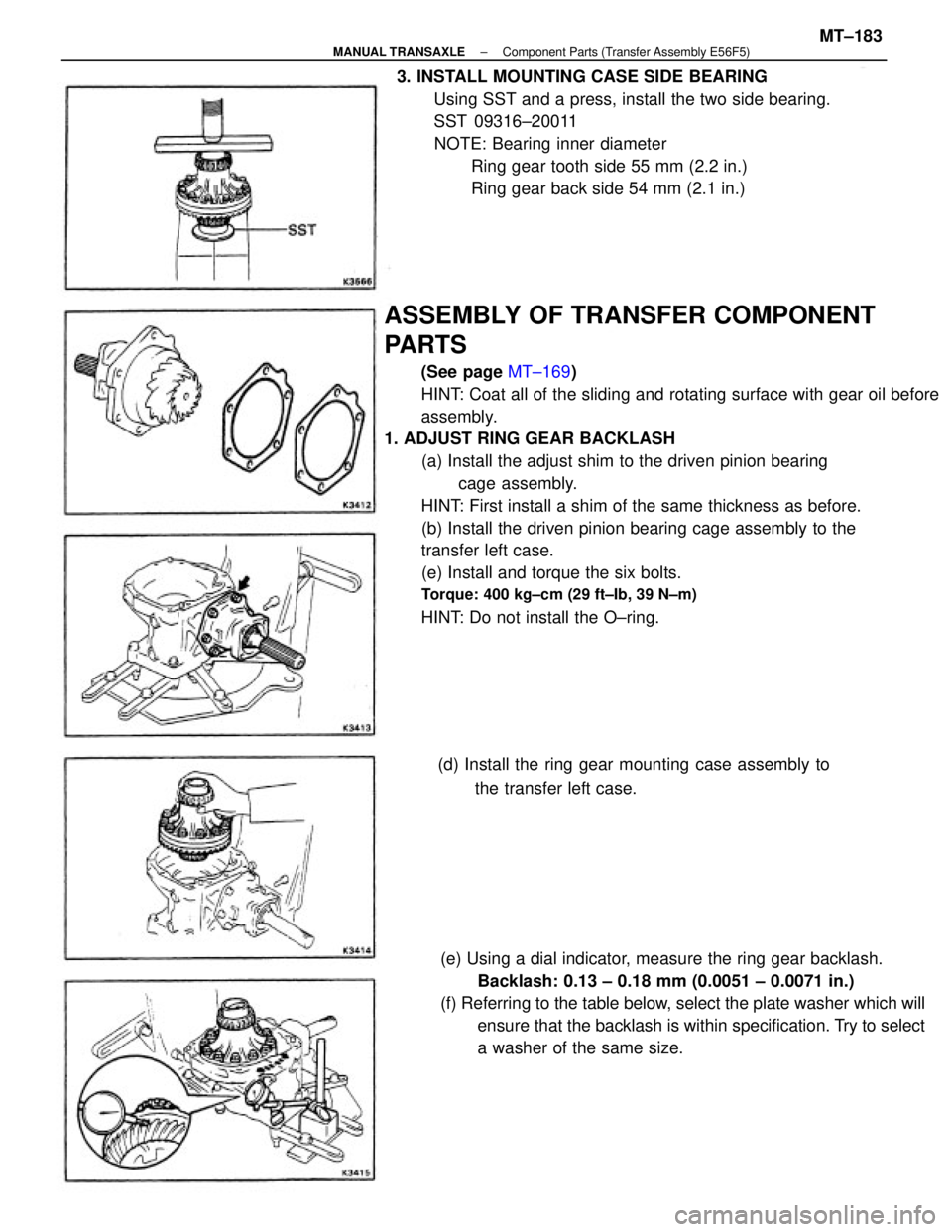
ASSEMBLY OF TRANSFER COMPONENT
PARTS
(See page MT±169)
HINT: Coat all of the sliding and rotating surface with gear oil before
assembly.
1. ADJUST RING GEAR BACKLASH
(a) Install the adjust shim to the driven pinion bearing
cage assembly.
HINT: First install a shim of the same thickness as before.
(b) Install the driven pinion bearing cage assembly to the
transfer left case.
(e) Install and torque the six bolts.
Torque: 400 kg±cm (29 ft±Ib, 39 N±m)
HINT: Do not install the O±ring.
(e) Using a dial indicator, measure the ring gear backlash.
Backlash: 0.13 ± 0.18 mm (0.0051 ± 0.0071 in.)
(f) Referring to the table below, select the plate washer which will
ensure that the backlash is within specification. Try to select
a washer of the same size. 3. INSTALL MOUNTING CASE SIDE BEARING
Using SST and a press, install the two side bearing.
SST 09316±20011
NOTE: Bearing inner diameter
Ring gear tooth side 55 mm (2.2 in.)
Ring gear back side 54 mm (2.1 in.)
(d) Install the ring gear mounting case assembly to
the transfer left case.
± MANUAL TRANSAXLEComponent Parts (Transfer Assembly E56F5)MT±183
Page 2129 of 2389
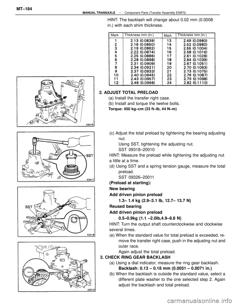
(c) Adjust the total preload by tightening the bearing adjusting
nut.
Using SST, tightening the adjusting nut.
SST 09318±20010
HINT: Measure the preload while tightening the adjusting nut
a little at a time.
(d) Using SST and a spring tension gauge, measure the total
preload.
SST 09326±20011
(Preload at starting):
New bearing
Add driven pinion preload
1.3± 1.4 kg (2.9±3.1 Ib, 12.7± 13.7 N)
Reused bearing
Add driven pinion preload
0.5±0.9kg (1.1 ±2.0Ib,4.9±8.8 N)
HINT: Turn the output shaft counterclockwise and clockwise
several times.
(e) When the standard value for total preload is exceeded, re-
move the transfer right case, push in the adjusting nut and
outer race.
Again adjust the total preload.
3. CHECK RING GEAR BACKLASH
(a) Using a dial indicator, measure the ring gear backlash.
Backlash: 0.13 ± 0.18 mm (0.0051 ± 0.0071 in.)
(b) When the backlash is outside the standard value, select a
different plate washer to the one selected step 2. Again
adjust the backlash and total preload. 2. ADJUST TOTAL PRELOAD
(a) Install the transfer right case.
(b) Install and torque the twelve bolts.
Torque: 450 kg±cm (33 ft±lb, 44 N±m)
HINT: The backlash will change about 0.02 mm (0.0008
in.) with each shim thickness.
Thickness mm (in.) Thickness mm (in.)
Mark
Mark
± MANUAL TRANSAXLEComponent Parts (Transfer Assembly E56F5)MT±184
Page 2131 of 2389
9. INSTALL TRANSFER RIGHT CASE
(a) Remove any packing material and be careful not to drop oil
on the contacting surfaces of the transfer left case or right
case.
(b) Apply seal packing to the transfer left case as shown in the
figure.
Seal packing: Part No.08826±00090, THREE BOND
1281 or equivalent
HINT: Install the transfer right case as soon as the seal pack-
ing is applied. 7. INSTALL DRIVEN PINION BEARING CAGE
ASSEMBLY
(a) Coat the O±ring with gear oil.
(b) Install the O±ring to the driven pinion bearing cage.
(c) Install the driven pinion bearing cage with adjust shim
(Previously selected) to the transfer left case.
(d) Install and torque the six bolts.
Torque: 400 kg±cm (29 ft±Ib. 39 N±m)
6. REMOVE DRIVEN PINION BEARING CAGE
ASSEMBLY
(a) Remove the six bolts and bearing cage assembly.
8. INSTALL RING GEAR MOUNTING CASE ASSEMBLY(b) Remove the ring gear mounting case assembly.
± MANUAL TRANSAXLEComponent Parts (Transfer Assembly F56 F5)MT±186