Page 1032 of 2389

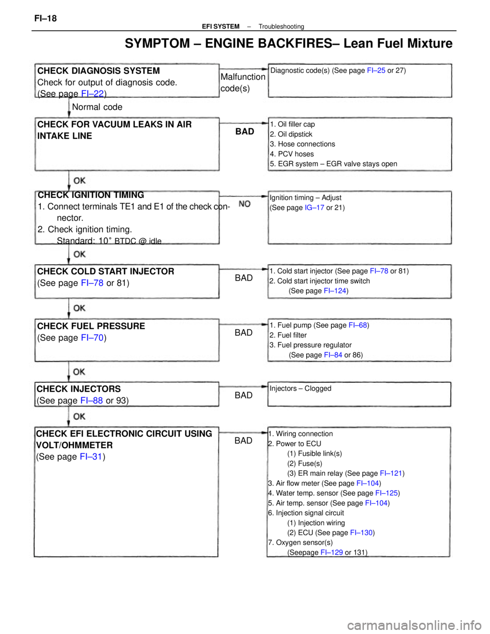
1. Wiring connection
2. Power to ECU
(1) Fusible link(s)
(2) Fuse(s)
(3) ER main relay (See page FI±121)
3. Air flow meter (See page FI±104)
4. Water temp. sensor (See page FI±125)
5. Air temp. sensor (See page FI±104)
6. Injection signal circuit
(1) Injection wiring
(2) ECU (See page FI±130)
7. Oxygen sensor(s)
(Seepage FI±129 or 131)
CHECK IGNITION TIMING
1. Connect terminals TE1 and E1 of the check con-
nector.
2. Check ignition timing.
Standard: 10
° BTDC @ idle
1. Oil filler cap
2. Oil dipstick
3. Hose connections
4. PCV hoses
5. EGR system ± EGR valve stays open
CHECK EFI ELECTRONIC CIRCUIT USING
VOLT/OHMMETER
(See page FI±31)
1. Cold start injector (See page FI±78 or 81)
2. Cold start injector time switch
(See page FI±124)
1. Fuel pump (See page FI±68)
2. Fuel filter
3. Fuel pressure regulator
(See page FI±84 or 86)
CHECK DIAGNOSIS SYSTEM
Check for output of diagnosis code.
(See page FI±22)
SYMPTOM ± ENGINE BACKFIRES± Lean Fuel Mixture
CHECK FOR VACUUM LEAKS IN AIR
INTAKE LINE
CHECK COLD START INJECTOR
(See page FI±78 or 81)
CHECK FUEL PRESSURE
(See page FI±70)
Diagnostic code(s) (See page FI±25 or 27)
Ignition timing ± Adjust
(See page IG±17 or 21)
CHECK INJECTORS
(See page FI±88 or 93)Injectors ± Clogged
Malfunction
code(s)
Normal code
BAD
BAD
BAD BAD
BAD
± EFI SYSTEMTroubleshootingFI±18
Page 1035 of 2389
1. Spark plug
2. Compression pressure
Minimum: 10.0 kg/cm
2
(142 psi, 981 kPa)
at 250 rpm
3. Valve clearance
Standard:
3F±FE IN 0.19±0.29 mm
(0.007 ± 0.011 in.)
EX 0.28 ± 0.38 mm
(0.011 ± 0.015 in.)
2VZ±FE IN 0.13±0.23
(0.005 ± 0.009 in.)
EX 0.27± 0.37 mm
(0.011 ± 0.015 in.)
1. Wiring connection
2. Power to ECU
(1) Fusible link(s)
(2) Fuse(s)
(3) ER main relay (See page FI±121)
3. Air flow meter (See page FI±104)
4. Water temp. sensor (See page FI±125)
5. Air temp. sensor (See page FI±104)
6. Throttle position sensor
(See page FI±106, 110 or 112)
7. Injection signal circuit
(1) Injector wiring
(2) ECU (See page FI±130)
CHECK SPARK PLUGS
Standard: 1.1 mm (0±043 in.)
HINT: Check compression pressure and
valve clearance if necessary.
CHECK EFI ELECTRONIC CIRCUIT USING
VOLT/OHMMETER
(See page FI±31) OK CONTINUED FROM PAGE FI±20
BAD
± EFI SYSTEMTroubleshootingFI±21
Page 1047 of 2389
ON±VEHICLE INSPECTION
1. CHECK FUEL PUMP OPERATION
(a) Turn the ignition switch ON.
NOTICE: Do not start the engine.
(b) Using SST, connect terminals +B and FP of the check con-
nector.
SST 09843±18020
(e) Turn the ignition switch OFF.
If there is no pressure, check the following
parts:
wFusible links
wFuses (ER 15 A, IGN 7.5 A)
wER main relay
wFuel pump
wECU
wWiring connections (e) Check that there is pressure in the hose from the fuel
filter.
HINT: At this time, you will hear fuel return noise.
(d) Remove SST.
SST 09843±18020
± EFI SYSTEMFuel System (Fuel Pump)FI±70
Page 1056 of 2389

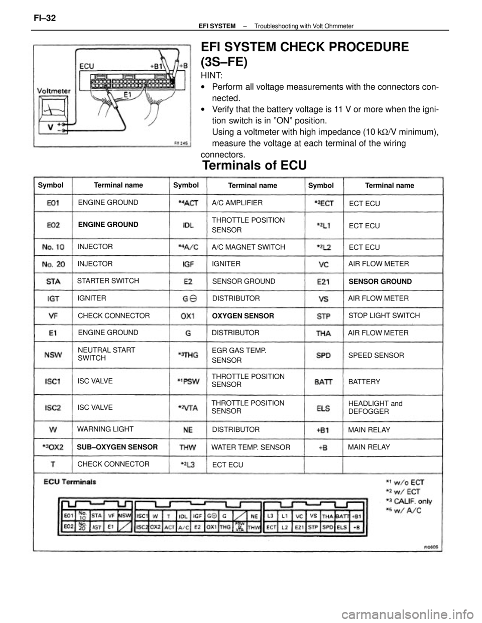
EFI SYSTEM CHECK PROCEDURE
(3S±FE)
HINT:
wPerform all voltage measurements with the connectors con-
nected.
wVerify that the battery voltage is 11 V or more when the igni-
tion switch is in ºONº position.
Using a voltmeter with high impedance (10 kW/V minimum),
measure the voltage at each terminal of the wiring
connectors.
THROTTLE POSITION
SENSORTHROTTLE POSITION
SENSOR
THROTTLE POSITION
SENSOR
Terminals of ECU
NEUTRAL START
SWITCH
HEADLIGHT and
DEFOGGER EGR GAS TEMP.
SENSOR
WATER TEMP. SENSOR SUB±OXYGEN SENSORA/C MAGNET SWITCH
STOP LIGHT SWITCH
CHECK CONNECTORCHECK CONNECTORAIR FLOW METER
AIR FLOW METER
AIR FLOW METER STARTER SWITCH
SENSOR GROUND SENSOR GROUND ENGINE GROUND
ENGINE GROUND ENGINE GROUND
OXYGEN SENSOR
WARNING LIGHTA/C AMPLIFIER
SPEED SENSORTerminal name Terminal name Terminal name
DISTRIBUTORDISTRIBUTOR
DISTRIBUTOR
MAIN RELAYMAIN RELAY ISC VALVE
ISC VALVE INJECTORINJECTOR Symbol
BATTERY Symbol
Symbol
IGNITERECT ECUECT ECU
ECT ECU
IGNITER
ECT ECU
± EFI SYSTEMTroubleshooting with Volt OhmmeterFI±32
Page 1058 of 2389
Check that there is voltage between ECU terminal +B or +B1 and
body ground. (IG SW ON) No voltage between ECU terminals +B or +B1 and El.
(IG SW ON)
Check wiring between ECU terminal E1 and body
ground.
Check wiring between ER main
relay and battery.Check fuse, fusible link and
ignition switch.
Check ER main relay.Try another ECU.
Repair or replace. Repair or replace.
Repair or replace.
Ignition SW ON
STD voltageTerminals
Condition
Replace.
Trouble
BAD BADBAD
BAD No.
± EFI SYSTEMTroubleshooting with Volt OhmmeterFI±34
Page 1067 of 2389
Check that there is voltage at STA (50) terminal of starter.
(IG SW START) STD voltage: 6 ± 14 v Check fusible link, battery, wiring, ignition
switch clutch start switch, starter relay and
neutral start switch..Check wiring between ECU terminal E1 and body
ground. No voltage between ECU terminals STA and E1.
OG SW START)
Check wiring between ignition switch
terminal ST1 and starter terminal STA (50).Check wiring between ECU terminal STA
and ignition switch terminal ST1.
Check starter
operation.
Repair or replace.
Repair or replace.Repair or replace.
Try another ECU.STD voltage
Check starter.
No voltage
Cranking
Terminals ConditionTrouble
BAD
BADBAD BAD No.
± EFI SYSTEMTroubleshooting with Volt OhmmeterFI±43
Page 1074 of 2389

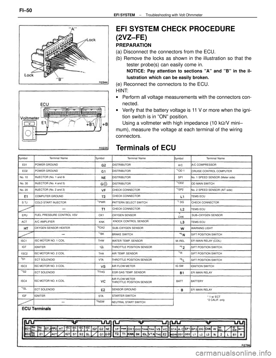
EFI SYSTEM CHECK PROCEDURE
(2VZ±FE)
PREPARATION
(a) Disconnect the connectors from the ECU.
(b) Remove the locks as shown in the illustration so that the
tester probe(s) can easily come in.
NOTICE: Pay attention to sections ºAº and ºBº in the il-
lustration which can be easily broken.
(e) Reconnect the connectors to the ECU.
HINT:
wPerform all voltage measurements with the connectors con-
nected.
wVerify that the battery voltage is 11 V or more when the igni-
tion switch is in ºONº position.
Using a voltmeter with high impedance (10 k
�/V mini±
mum), measure the voltage at each terminal of the wiring
connectors.
AIR FLOW METER
THROTTLE POSITION SENSOR
Terminals of ECU
No. 1 SPEED SENSOR (Meter side)
No. 2 SPEED SENSOR (AlT side)
THROTTLE POSITION SENSOR FUEL PRESSURE CONTROL VSV
THROTTLE POSITION SENSORCRUISE CONTROL COMPUTER
* 1 w/ ECT
*2 CALIF. only KNOCK CONTROL SENSOR PATTERN SELECT SWITCH
OXYGEN SENSOR HEATER
NEUTRAL START SWITCHEGR GAS TEMP. SENSOR INJECTOR (No. 2 and 3)INJECTOR (No. 4 and 5)
SIFT POSITION SWITCH.
ISC MOTOR NO. 3 COILINJECTOR (No. 1 and 6i
ISC MOTOR NO. 1 COIL
ISC MOTOR NO. 4 COILSIFT POSITION SWITCH ISC MOTOR NO. 2 COILWATER TEMP. SENSORSUB±OXYGEN SENSOR
SIFT POSITION SWITCH COLD START INJECTOR
EFI MAIN RELAY (COIL)
SIFT POSITION SWITCHSUB±OXYGEN SENSOR CHECK CONNECTOR
COMPUTER GROUND
CHECK CONNECTORCHECK CONNECTOR CHECK CONNECTOR
AIR TEMP. SENSORA/C COMPRESSOR
SENSOR GROUNDTerminal Name
OXYGEN SENSOROD MAIN SWITCH
STARTER SWITCHIGNITION SWITCH Terminal Name
AIR FLOW METERTerminal Name
POWER GROUND
POWER GROUND
WARNING LIGHT
EFI MAIN RELAY BRAKE SWITCH
EFt MAIN RELAY ECT SOLENOID
ECT SOLENOIDA/C AMPLIFIER
ECT SOLENOIDDISTRIBUTOR
DISTRIBUTOR DISTRIBUTOR
DISTRIBUTOR
TEMS ECU
TEMS ECU
TEMS ECU Symbol Symbol Symbol
BATTERY IGNITER
IGNITER
*2NSW
*1OD2
No. 30 No. 10
No. 20
*1PWR
*2OX2
M±REL
*1OD 1
*2CHK
*2THGIG SW
*1SP2
BATT
*1SL
*1 DG
1S1THW
*1S2
*1BK
ISC4 1SC2 ISC1
ISC3VTAOX1
ACTS TJSP1
THA
STAKNK EO2 E01
IGT
*1R A/C
EPU
1
L
IGF
± EFI SYSTEMTroubleshooting with Volt OhmmeterFI±50
Page 1077 of 2389
Check that there is voltage between ECU terminal M±REL and body
ground. (IG SW ON)Check that there is voltage between ECU terminal IG SW and body
ground. (IG SW ON).
There is no voltage between ECU terminals M±REL and El.
(IG SW ON)There is no voltage between ECU terminals IG SW and El.
(IG SW ON)
Check wiring between ECU terminal E 1 and body
ground.Check wiring between ECU terminal E t and body ground.
Check EFI main relay and wiring
harness. (See page F!±121 )Check fuse, fusible link and
ignition switch.
Repair or replace.Repair or replace. Repair or replace.
Try another ECU.
Try another ECU.
Try another ECU.
wM±REL ± E1 wIG SW ± E1
Replace. BADBAD
BAD
BAD
± EFI SYSTEMTroubleshooting with Volt OhmmeterFI±53