Page 1313 of 2389
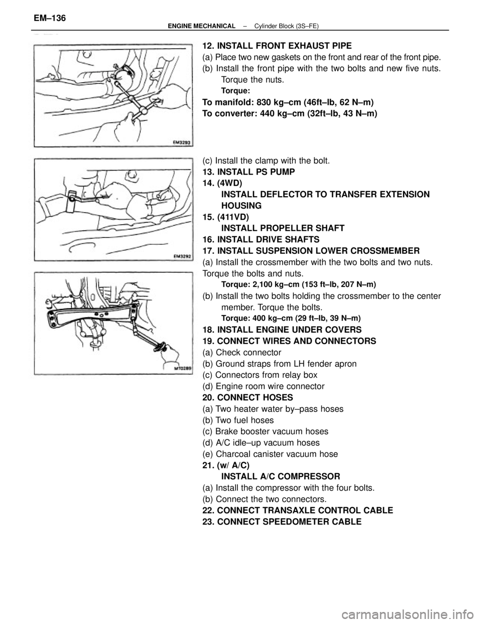
(c) Install the clamp with the bolt.
13. INSTALL PS PUMP
14. (4WD)
INSTALL DEFLECTOR TO TRANSFER EXTENSION
HOUSING
15. (411VD)
INSTALL PROPELLER SHAFT
16. INSTALL DRIVE SHAFTS
17. INSTALL SUSPENSION LOWER CROSSMEMBER
(a) Install the crossmember with the two bolts and two nuts.
Torque the bolts and nuts.
Torque: 2,100 kg±cm (153 ft±lb, 207 N±m)
(b) Install the two bolts holding the crossmember to the center
member. Torque the bolts.
Torque: 400 kg±cm (29 ft±Ib, 39 N±m)
18. INSTALL ENGINE UNDER COVERS
19. CONNECT WIRES AND CONNECTORS
(a) Check connector
(b) Ground straps from LH fender apron
(c) Connectors from relay box
(d) Engine room wire connector
20. CONNECT HOSES
(a) Two heater water by±pass hoses
(b) Two fuel hoses
(c) Brake booster vacuum hoses
(d) A/C idle±up vacuum hoses
(e) Charcoal canister vacuum hose
21. (w/ A/C)
INSTALL A/C COMPRESSOR
(a) Install the compressor with the four bolts.
(b) Connect the two connectors.
22. CONNECT TRANSAXLE CONTROL CABLE
23. CONNECT SPEEDOMETER CABLE 12. INSTALL FRONT EXHAUST PIPE
(a) Place two new gaskets on the front and rear of the front pipe.
(b) Install the front pipe with the two bolts and new five nuts.
Torque the nuts.
Torque:
To manifold: 830 kg±cm (46ft±Ib, 62 N±m)
To converter: 440 kg±cm (32ft±lb, 43 N±m)
± ENGINE MECHANICALCylinder Block (3S±FE)EM±136
Page 1318 of 2389
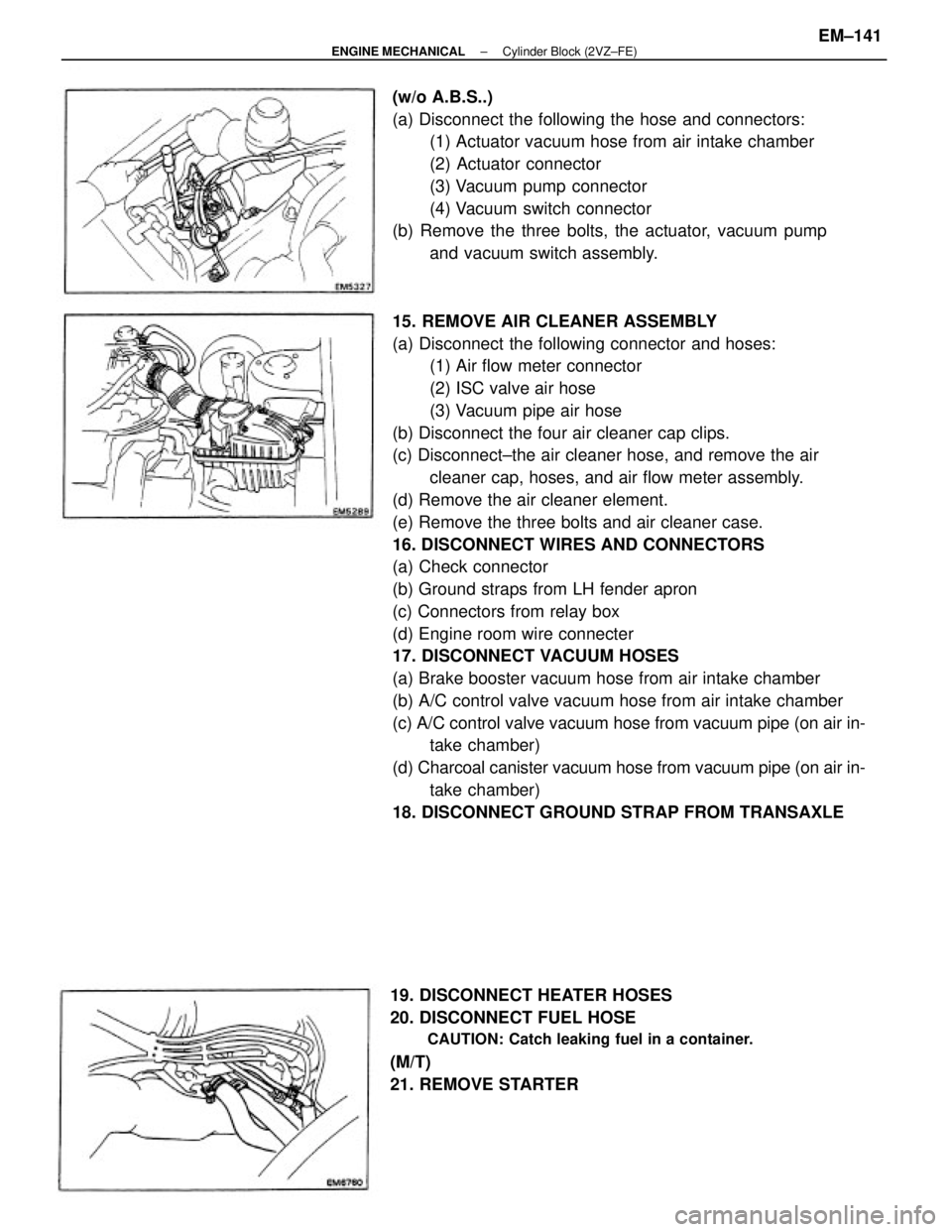
15. REMOVE AIR CLEANER ASSEMBLY
(a) Disconnect the following connector and hoses:
(1) Air flow meter connector
(2) ISC valve air hose
(3) Vacuum pipe air hose
(b) Disconnect the four air cleaner cap clips.
(c) Disconnect±the air cleaner hose, and remove the air
cleaner cap, hoses, and air flow meter assembly.
(d) Remove the air cleaner element.
(e) Remove the three bolts and air cleaner case.
16. DISCONNECT WIRES AND CONNECTORS
(a) Check connector
(b) Ground straps from LH fender apron
(c) Connectors from relay box
(d) Engine room wire connecter
17. DISCONNECT VACUUM HOSES
(a) Brake booster vacuum hose from air intake chamber
(b) A/C control valve vacuum hose from air intake chamber
(c) A/C control valve vacuum hose from vacuum pipe (on air in-
take chamber)
(d) Charcoal canister vacuum hose from vacuum pipe (on air in-
take chamber)
18. DISCONNECT GROUND STRAP FROM TRANSAXLE (w/o A.B.S..)
(a) Disconnect the following the hose and connectors:
(1) Actuator vacuum hose from air intake chamber
(2) Actuator connector
(3) Vacuum pump connector
(4) Vacuum switch connector
(b) Remove the three bolts, the actuator, vacuum pump
and vacuum switch assembly.
19. DISCONNECT HEATER HOSES
20. DISCONNECT FUEL HOSE
CAUTION: Catch leaking fuel in a container.
(M/T)
21. REMOVE STARTER
± ENGINE MECHANICALCylinder Block (2VZ±FE)EM±141
Page 1319 of 2389
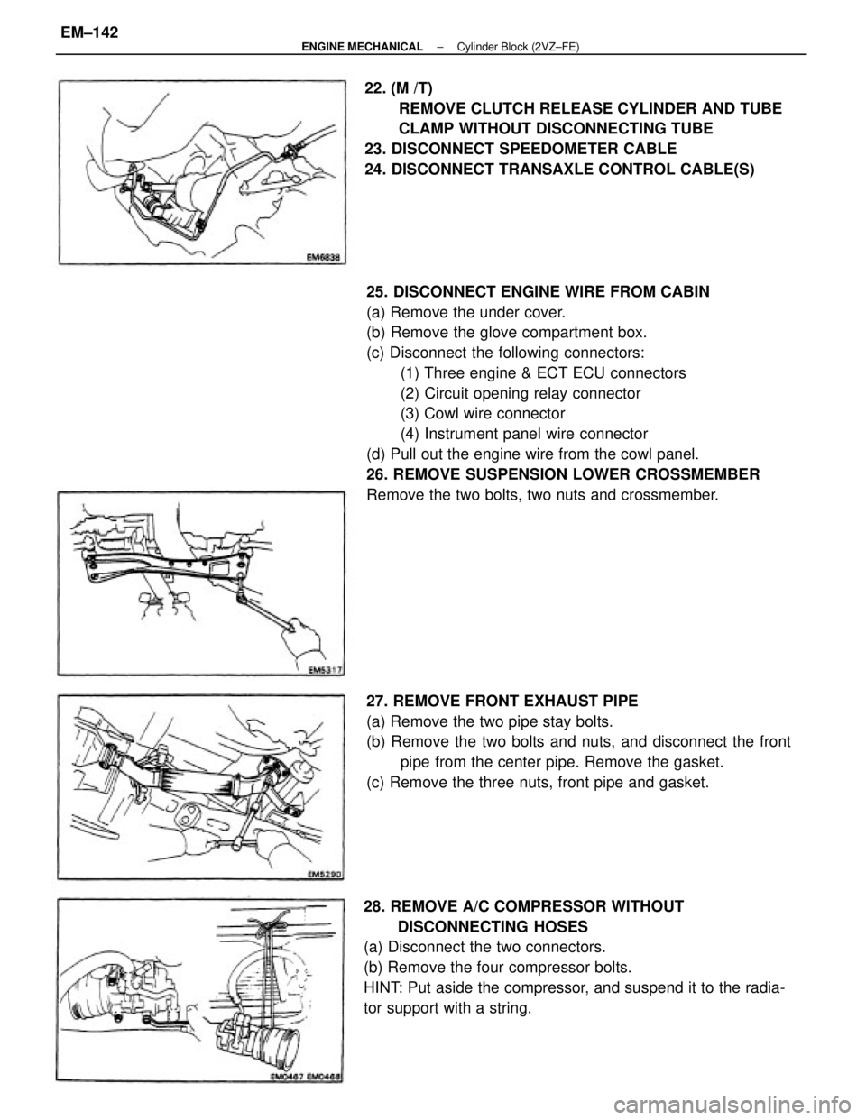
25. DISCONNECT ENGINE WIRE FROM CABIN
(a) Remove the under cover.
(b) Remove the glove compartment box.
(c) Disconnect the following connectors:
(1) Three engine & ECT ECU connectors
(2) Circuit opening relay connector
(3) Cowl wire connector
(4) Instrument panel wire connector
(d) Pull out the engine wire from the cowl panel.
26. REMOVE SUSPENSION LOWER CROSSMEMBER
Remove the two bolts, two nuts and crossmember.
28. REMOVE A/C COMPRESSOR WITHOUT
DISCONNECTING HOSES
(a) Disconnect the two connectors.
(b) Remove the four compressor bolts.
HINT: Put aside the compressor, and suspend it to the radia-
tor support with a string.22. (M /T)
REMOVE CLUTCH RELEASE CYLINDER AND TUBE
CLAMP WITHOUT DISCONNECTING TUBE
23. DISCONNECT SPEEDOMETER CABLE
24. DISCONNECT TRANSAXLE CONTROL CABLE(S)
27. REMOVE FRONT EXHAUST PIPE
(a) Remove the two pipe stay bolts.
(b) Remove the two bolts and nuts, and disconnect the front
pipe from the center pipe. Remove the gasket.
(c) Remove the three nuts, front pipe and gasket.
± ENGINE MECHANICALCylinder Block (2VZ±FE)EM±142
Page 1349 of 2389
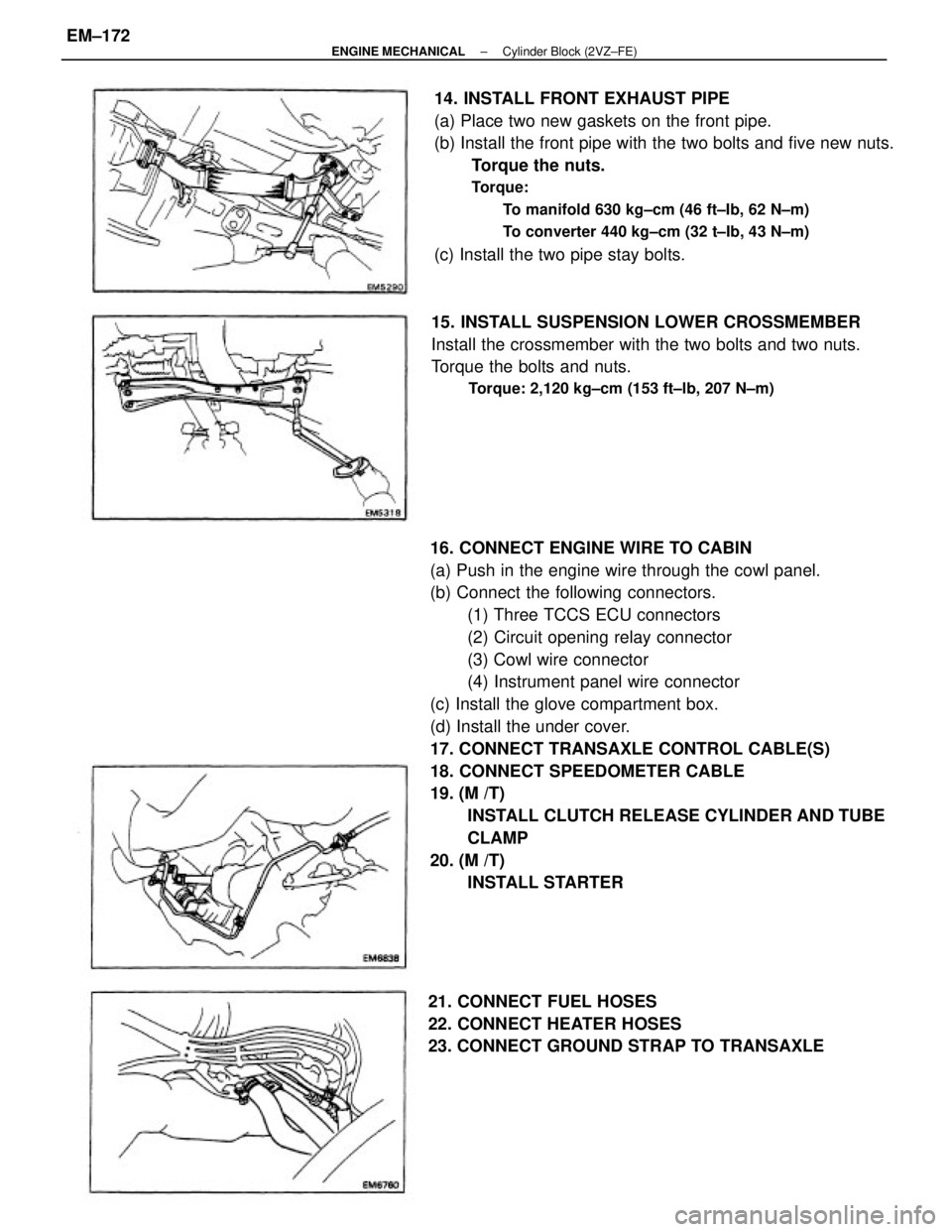
16. CONNECT ENGINE WIRE TO CABIN
(a) Push in the engine wire through the cowl panel.
(b) Connect the following connectors.
(1) Three TCCS ECU connectors
(2) Circuit opening relay connector
(3) Cowl wire connector
(4) Instrument panel wire connector
(c) Install the glove compartment box.
(d) Install the under cover.
17. CONNECT TRANSAXLE CONTROL CABLE(S)
18. CONNECT SPEEDOMETER CABLE
19. (M /T)
INSTALL CLUTCH RELEASE CYLINDER AND TUBE
CLAMP
20. (M /T)
INSTALL STARTER 14. INSTALL FRONT EXHAUST PIPE
(a) Place two new gaskets on the front pipe.
(b) Install the front pipe with the two bolts and five new nuts.
Torque the nuts.
Torque:
To manifold 630 kg±cm (46 ft±Ib, 62 N±m)
To converter 440 kg±cm (32 t±Ib, 43 N±m)
(c) Install the two pipe stay bolts.
15. INSTALL SUSPENSION LOWER CROSSMEMBER
Install the crossmember with the two bolts and two nuts.
Torque the bolts and nuts.
Torque: 2,120 kg±cm (153 ft±lb, 207 N±m)
21. CONNECT FUEL HOSES
22. CONNECT HEATER HOSES
23. CONNECT GROUND STRAP TO TRANSAXLE
± ENGINE MECHANICALCylinder Block (2VZ±FE)EM±172
Page 1350 of 2389
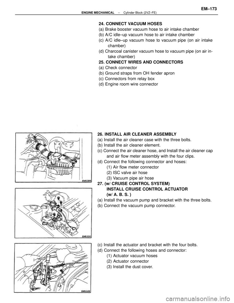
26. INSTALL AIR CLEANER ASSEMBLY
(a) Install the air cleaner case with the three bolts.
(b) Install the air cleaner element.
(c) Connect the air cleaner hose, and Install the air cleaner cap
and air flow meter assembly with the four clips.
(d) Connect the following connector and hoses:
(1) Air flow meter connector
(2) ISC valve air hose
(3) Vacuum pipe air hose
27. (w/ CRUISE CONTROL SYSTEM)
INSTALL CRUISE CONTROL ACTUATOR
(w/ A. B. S. )
(a) Install the vacuum pump and bracket with the three bolts.
(b) Connect the vacuum pump connector.24. CONNECT VACUUM HOSES
(a) Brake booster vacuum hose to air intake chamber
(b) A/C idle±up vacuum hose to air intake chamber
(c) A/C idle±up vacuum hose to vacuum pipe (on air intake
chamber)
(d) Charcoal canister vacuum hose to vacuum pipe (on air in-
take chamber)
25. CONNECT WIRES AND CONNECTORS
(a) Check connector
(b) Ground straps from OH fender apron
(c) Connectors from relay box
(d) Engine room wire connector
(c) Install the actuator and bracket with the four bolts.
(d) Connect the following hoses and connector:
(1) Actuator vacuum hoses
(2) Actuator connector
(3) Install the dust cover.
± ENGINE MECHANICALCylinder Block (2VZ±FE)EM±173
Page 1422 of 2389
Terminal (Female)
Housing (Female)
Housing (Male)
Terminal (Male)
Wire
Harness
(W/H)Electric Wire
Terminal
Housing
Fuse
Other J/B
(Junction Block)
R/B
(Relay Block)
Insulator
Copper Wires
(Conductor)
B = Black W = White
L = Blue BR = Brown
V = Violet SB = Sky Blue
R = Red G = Green
P = Pink LG = Light Green
Y = Yellow GR = Gray
O = Orange
A±2
INTRODUCTION±GENERAL INFORMATION
3
Wire Harness Repair Manual (RM1022E)
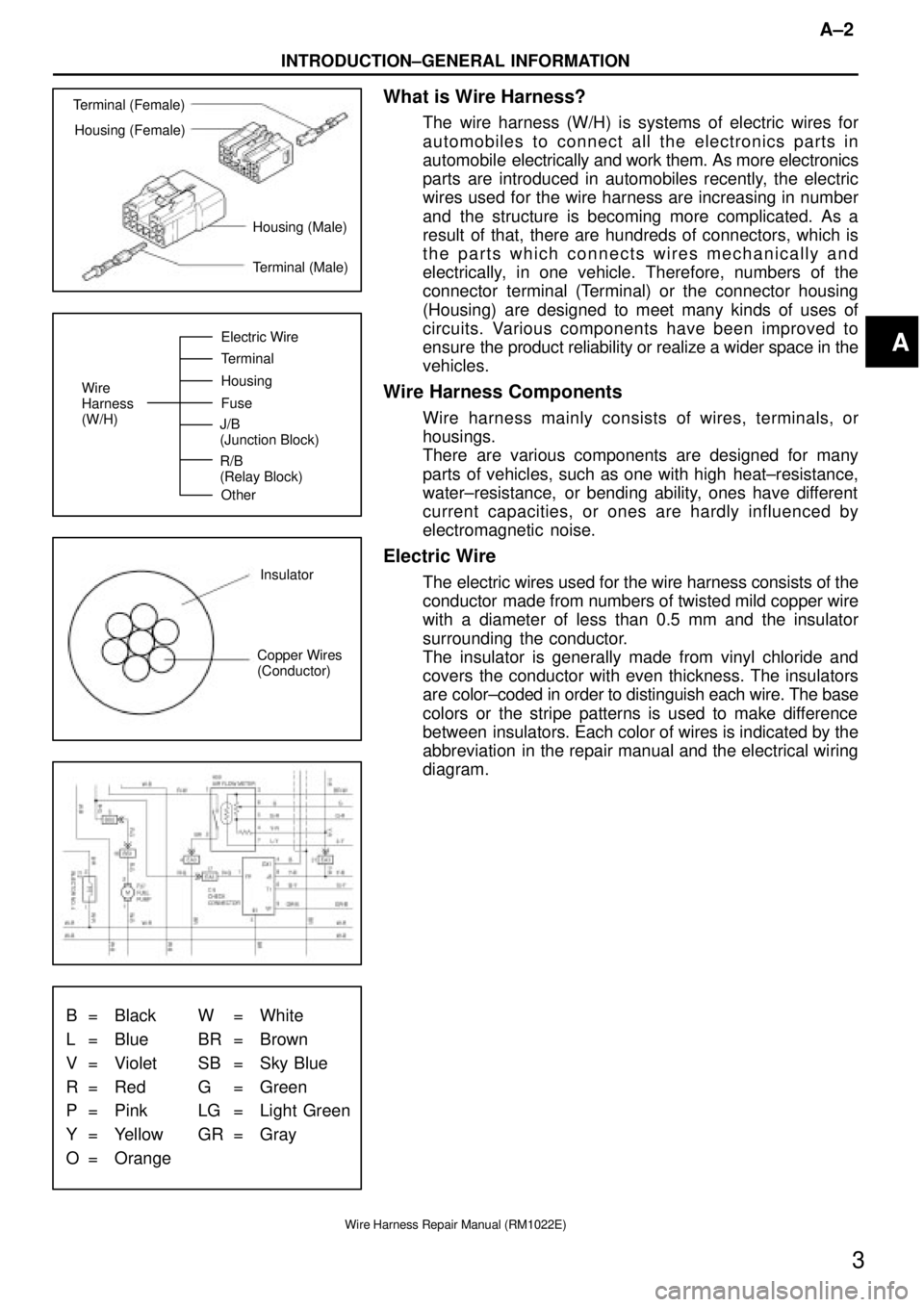
What is Wire Harness?
The wire harness (W/H) is systems of electric wires for
automobiles to connect all the electronics parts in
automobile electrically and work them. As more electronics
parts are introduced in automobiles recently, the electric
wires used for the wire harness are increasing in number
and the structure is becoming more complicated. As a
result of that, there are hundreds of connectors, which is
the parts which connects wires mechanically and
electrically, in one vehicle. Therefore, numbers of the
connector terminal (Terminal) or the connector housing
(Housing) are designed to meet many kinds of uses of
circuits. Various components have been improved to
ensure the product reliability or realize a wider space in the
vehicles.
Wire Harness Components
Wire harness mainly consists of wires, terminals, or
housings.
There are various components are designed for many
parts of vehicles, such as one with high heat±resistance,
water±resistance, or bending ability, ones have different
current capacities, or ones are hardly influenced by
electromagnetic noise.
Electric Wire
The electric wires used for the wire harness consists of the
conductor made from numbers of twisted mild copper wire
with a diameter of less than 0.5 mm and the insulator
surrounding the conductor.
The insulator is generally made from vinyl chloride and
covers the conductor with even thickness. The insulators
are color±coded in order to distinguish each wire. The base
colors or the stripe patterns is used to make difference
between insulators. Each color of wires is indicated by the
abbreviation in the repair manual and the electrical wiring
diagram.
A
Page 1425 of 2389
![TOYOTA CAMRY V20 1986 Service Information To Ignition SW
IG Terminal
Fuse
Relay
SW2 SolenoidVoltmeter [A]
[B]
[C] SW1
Ohmmeter
SW
INTRODUCTION±HOW TO PERFORM FOR SYSTEM INSPECTION
A±5
6
Wire Harness Repair Manual (RM1022E)
HOW TO PERFORM FO TOYOTA CAMRY V20 1986 Service Information To Ignition SW
IG Terminal
Fuse
Relay
SW2 SolenoidVoltmeter [A]
[B]
[C] SW1
Ohmmeter
SW
INTRODUCTION±HOW TO PERFORM FOR SYSTEM INSPECTION
A±5
6
Wire Harness Repair Manual (RM1022E)
HOW TO PERFORM FO](/manual-img/14/57449/w960_57449-1424.png)
To Ignition SW
IG Terminal
Fuse
Relay
SW2 SolenoidVoltmeter [A]
[B]
[C] SW1
Ohmmeter
SW
INTRODUCTION±HOW TO PERFORM FOR SYSTEM INSPECTION
A±5
6
Wire Harness Repair Manual (RM1022E)
HOW TO PERFORM FOR SYSTEM INSPECTION
This inspection procedure is a simple troubleshooting which should be carried out on the vehicle during
system operation and is based on the assumption of system component trouble
Always inspect the trouble taking the following items into consideration:
�Ground point fault
�Open or short circuit of the wire harness
�Connector or terminal connection fault
�Fuse or fusible link fault
NOTICE:
�This is an on±vehicle inspection during system operation.
Therefore, inspect the trouble with due regard for safety.
�If connecting the battery directly, be careful not to cause a short circuit, and select the applicable
voltage.
1. Voltage Check
(a)Establish conditions in which voltage is present at the
check point.
Example:
[A] ± Ignition SW on
[B] ± Ignition SW and SW 1 on
[C] ± Ignition SW, SW 1 and Relay on (SW 2 off)
(b)Using a voltmeter, connect the negative (±) lead to a
good ground point or negative (±) battery terminal
and the positive (+) lead to the connector or
component terminal. This check can be done with a
test bulb instead of a voltmeter.
2. Continuity and Resistance Check
(a)Disconnect the battery terminal or wire so there is no
voltage between the check points.
(b)Contact the two leads of an ohmmeter to each of the
check points.
A
Page 1427 of 2389
![TOYOTA CAMRY V20 1986 Service Information Fuse Case Test Bulb
Short [A]
SW1
Short [B]
Relay
Light
Short [C]
SW2 SolenoidDisconnect
Disconnect DisconnectTo Ignition SW
IG Terminal
INTRODUCTION±HOW TO PERFORM FOR SYSTEM INSPECTION
A±7
8
Wire TOYOTA CAMRY V20 1986 Service Information Fuse Case Test Bulb
Short [A]
SW1
Short [B]
Relay
Light
Short [C]
SW2 SolenoidDisconnect
Disconnect DisconnectTo Ignition SW
IG Terminal
INTRODUCTION±HOW TO PERFORM FOR SYSTEM INSPECTION
A±7
8
Wire](/manual-img/14/57449/w960_57449-1426.png)
Fuse Case Test Bulb
Short [A]
SW1
Short [B]
Relay
Light
Short [C]
SW2 SolenoidDisconnect
Disconnect DisconnectTo Ignition SW
IG Terminal
INTRODUCTION±HOW TO PERFORM FOR SYSTEM INSPECTION
A±7
8
Wire Harness Repair Manual (RM1022E)
4. Finding a Short Circuit
(a)Remove the blown fuse and eliminate all loads from
the fuse.
(b)Connect a test bulb in place of the fuse.
(c)Establish conditions in which the test bulb comes on.
Example:
[A] ± Ignition SW on
[B] ± Ignition SW and SW 1 on
[C] ± Ignition SW, SW 1 and Relay on (Connect the Relay)
and SW 2 off (or disconnect SW 2)
(d)Disconnect and reconnect the connectors while
watching the test bulb. The short lies between the
connector where the test bulb stays lit and the
connector where the bulb goes out.
(e)Find the exact location of the short by lightly shaking
the problem wire along the body.
CAUTION:
(a)Do not open the cover or the case of the ECU
unless absolutely necessary. (If the IC terminals
are touched, the IC may be destroyed by static
electricity.)
(b)When replacing the internal mechanism (ECU
part) of the digital meter, be careful that no part of
your body or clothing comes in contact with the
terminals of leads from the IC, etc. of the
replacement part (spare part).
A