Page 939 of 2389
6. REMOVE BRAKE TUBES
(w/o LSPV)
Using SST, remove the five brake tubes from the actuator.
SST 09751±36011
(w/ LS PV)
Using SST, remove the four brake tubes from actuator.
SST 09751±36011
7. REMOVE PROPORTIONING VALVE OR THREE±WAY
UNION
(w/o LSPV)
(a) Remove the two bolt and remove the proportioning
valve from the actuator.
(b) Remove the bolt and remove the valve bracket. 6. REMOVE CONTROL RELAYS
(a) Remove the connector from the wire harness clarnp.
(b) Remove the screw and remove the wire harness
clamp.
(d) Remove the relay cap from the control relays.
(e) Remove the two control relays from the actuator. (e) Remove the relay case.
± BRAKE SYSTEMAnti±lock Brake System (A.B.S.)BR±88
Page 942 of 2389
4. INSTALL THREE CUSHIONS AND HOLDERS
Install the three cushions to holders and install them to the
actuator. 3. INSTALL CONTROL RELAYS
(a) Install the two control relays in position.
(b) Install the relay cap onto the control relays.
5. INSTALL CONNECTOR TO CLAMP
Install the connector to the wire harness clamp.(d) Install the wire harness clamp with a screw.(c) Install the relay case.
± BRAKE SYSTEMAnti±lock Brake System (A.B.S.)BR±91
Page 944 of 2389

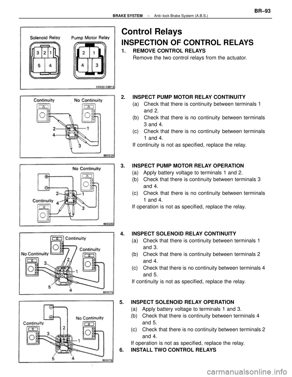
5. INSPECT SOLENOID RELAY OPERATION
(a) Apply battery voltage to terminals 1 and 3.
(b) Check that there is continuity between terminals 4
and 5.
(c) Check that there is no continuity between terminals 2
and 4.
If operation is not as specified, replace the relay.
6. INSTALL TWO CONTROL RELAYS4. INSPECT SOLENOID RELAY CONTINUITY
(a) Check that there is continuity between terminals 1
and 3.
(b) Check that there is continuity between terminals 2
and 4.
(c) Check that there is no continuity between terminals 4
and 5.
If continuity is not as specified, replace the relay. 2. INSPECT PUMP MOTOR RELAY CONTINUITY
(a) Check that there is continuity between terminals 1
and 2.
(b) Check that there is no continuity between terminals
3 and 4.
(c) Check that there is no continuity between terminals
1 and 4.
If continuity is not as specified, replace the relay.
3. INSPECT PUMP MOTOR RELAY OPERATION
(a) Apply battery voltage to terminals 1 and 2.
(b) Check that there is continuity between terminals 3
and 4.
(c) Check that there is no continuity between terminals
1 and 4.
If operation is not as specified, replace the relay.
Control Relays
INSPECTION OF CONTROL RELAYS
1. REMOVE CONTROL RELAYS
Remove the two control relays from the actuator.
± BRAKE SYSTEMAnti±lock Brake System (A.B.S.)BR±93
Page 953 of 2389

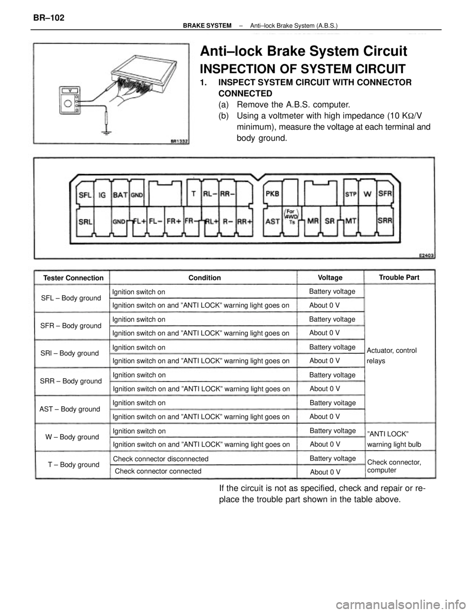
Anti±lock Brake System Circuit
INSPECTION OF SYSTEM CIRCUIT
1. INSPECT SYSTEM CIRCUIT WITH CONNECTOR
CONNECTED
(a) Remove the A.B.S. computer.
(b) Using a voltmeter with high impedance (10 K
�/V
minimum), measure the voltage at each terminal and
body ground.
If the circuit is not as specified, check and repair or re-
place the trouble part shown in the table above.
Ignition switch on and ºANTI LOCKº warning light goes on
Ignition switch on and ºANTI LOCKº warning light goes on
Ignition switch on and ºANTI LOCKº warning light goes onIgnition switch on and ºANTI LOCKº warning light goes on Ignition switch on and ºANTI LOCKº warning light goes on
Ignition switch on and ºANTI LOCKº warning light goes on
Check connector connectedºANTI LOCKº
warning light bulb
Check connector disconnected
Check connector,
computer Actuator, control
relays
AST ± Body groundSRR ± Body groundSRl ± Body ground SFR ± Body groundSFL ± Body ground
W ± Body ground
T ± Body ground Tester Connection
Ignition switch on Ignition switch on
Ignition switch on Ignition switch on
Ignition switch on Ignition switch on
Battery voltage Battery voltage
Battery voltage Battery voitage Battery voltage
Battery voltage Battery voltageTrouble Part
About 0 V
About 0 V About 0 V About 0 V
About 0 V
About 0 V
About 0 V ConditionVoltage
± BRAKE SYSTEMAnti±lock Brake System (A.B.S.)BR±102
Page 963 of 2389
1. INSPECT RELAY CONTINUITY
(a) Using an ohmmeter, check that there is continuity between
terminals 1 and 3.
(b) Check that there is continuity between terminals 2 and
4.
(c) Check that there is no continuity between terminals 4
and 5.
If continuity is not as specified, replace the relay.
2. INSPECT RELAY OPERATION
(a) Apply battery voltage across terminals 1 and 3.
(b) Using an ohmmeter, check that there is continuity between
terminals 4 and 5.
(e) Check that there is no continuity between terminals 2
and 4.
If operation is not as specified, replace the relay.
ENGINE MAIN RELAY
INSPECTION OF ENGINE MAIN RELAY
LOCATION:
3S±FE In the relay box in the engine compartment.
2VZ±FE On the LH fender apron rear side in the engine
compartment.
± CHARGING SYSTEMEngine Main RelayCH±16
Page 1008 of 2389
ON±VEHICLE INSPECTION
Low Temperature (Below 835C (1815F))
1. TURN IGNITION SWITCH ºONº
Check that the fan stops.
If not, check the cooling fan relay and water temperature
switch, and check for a separated connector or severed
wire between the cooling fan relay and water temperature
switch.
2. DISCONNECT WATER TEMPERATURE SWITCH
CONNECTOR
Check that fan rotates.
If not, check the cooling fan relay, fan motor, engine main
relay and fuse, and check for a short circuit between the
cooling fan relay and water temperature switch.
3: CONNECT WATER TEMPERATURE SWITCH
CONNECTOR
ELECTRIC COOLING FAN (3S±FE)
LOCATION OF ELECTRIC COOLING
FAN COMPONENTS
± COOLING SYSTEMElectric Cooling Fan (3S±FE)CO±21
Page 1009 of 2389

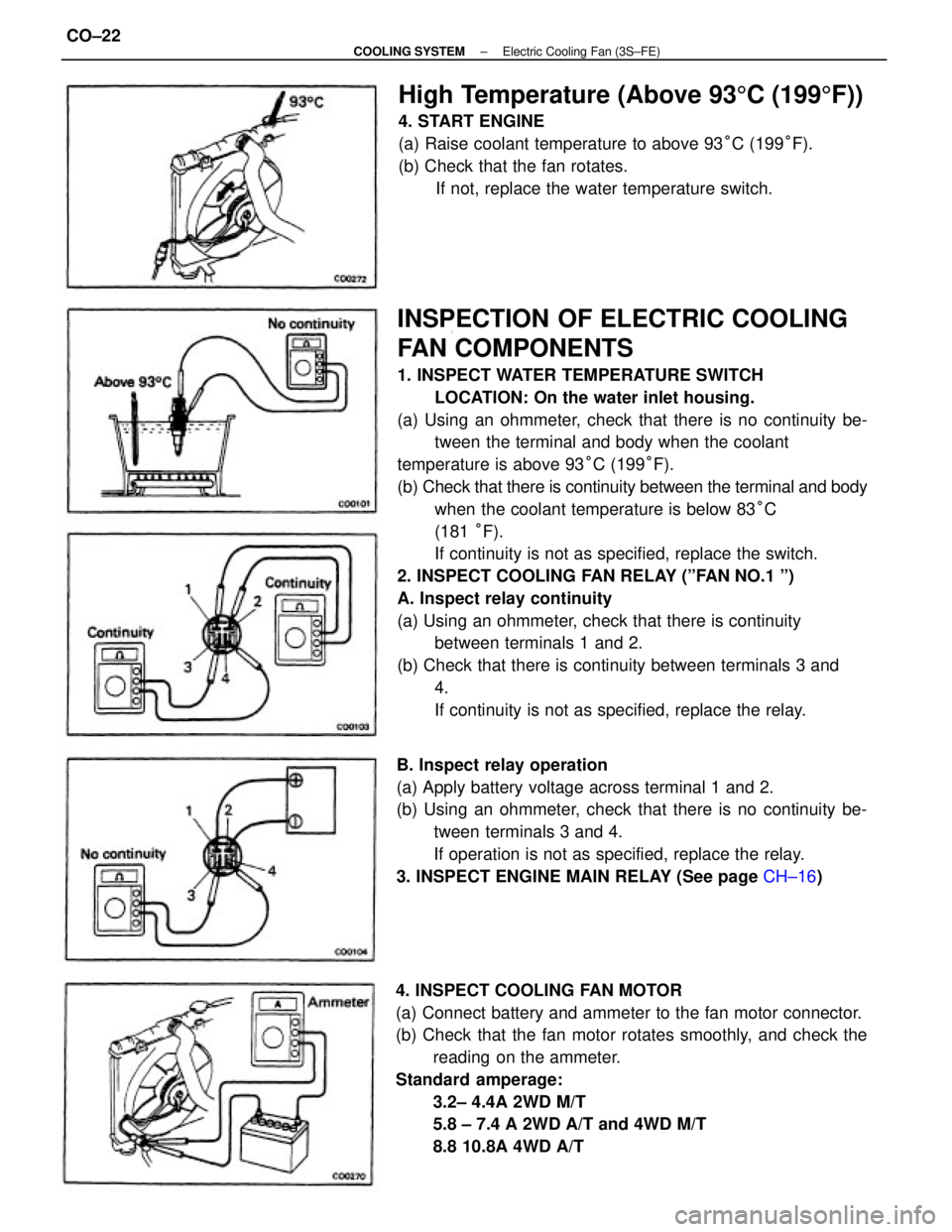
INSPECTION OF ELECTRIC COOLING
FAN COMPONENTS
1. INSPECT WATER TEMPERATURE SWITCH
LOCATION: On the water inlet housing.
(a) Using an ohmmeter, check that there is no continuity be-
tween the terminal and body when the coolant
temperature is above 93°C (199°F).
(b) Check that there is continuity between the terminal and body
when the coolant temperature is below 83°C
(181 °F).
If continuity is not as specified, replace the switch.
2. INSPECT COOLING FAN RELAY (ºFAN NO.1 º)
A. Inspect relay continuity
(a) Using an ohmmeter, check that there is continuity
between terminals 1 and 2.
(b) Check that there is continuity between terminals 3 and
4.
If continuity is not as specified, replace the relay.
4. INSPECT COOLING FAN MOTOR
(a) Connect battery and ammeter to the fan motor connector.
(b) Check that the fan motor rotates smoothly, and check the
reading on the ammeter.
Standard amperage:
3.2± 4.4A 2WD M/T
5.8 ± 7.4 A 2WD A/T and 4WD M/T
8.8 10.8A 4WD A/T B. Inspect relay operation
(a) Apply battery voltage across terminal 1 and 2.
(b) Using an ohmmeter, check that there is no continuity be-
tween terminals 3 and 4.
If operation is not as specified, replace the relay.
3. INSPECT ENGINE MAIN RELAY (See page CH±16)
High Temperature (Above 935C (1995F))
4. START ENGINE
(a) Raise coolant temperature to above 93°C (199°F).
(b) Check that the fan rotates.
If not, replace the water temperature switch.
± COOLING SYSTEMElectric Cooling Fan (3S±FE)CO±22
Page 1011 of 2389

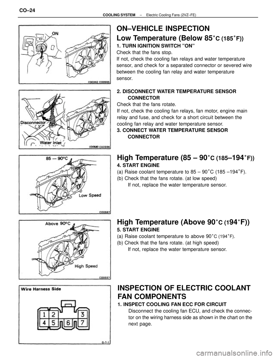
ON±VEHICLE INSPECTION
Low Temperature (Below 85
°C (185°F))
1. TURN IGNITION SWITCH ºONº
Check that the fans stop.
If not, check the cooling fan relays and water temperature
sensor, and check for a separated connector or severed wire
between the cooling fan relay and water temperature
sensor.
2. DISCONNECT WATER TEMPERATURE SENSOR
CONNECTOR
Check that the fans rotate.
If not, check the cooling fan relays, fan motor, engine main
relay and fuse, and check for a short circuit between the
cooling fan relay and water temperature sensor.
3. CONNECT WATER TEMPERATURE SENSOR
CONNECTOR
INSPECTION OF ELECTRIC COOLANT
FAN COMPONENTS
1. INSPECT COOLING FAN ECC FOR CIRCUIT
Disconnect the cooling fan ECU, and check the connec-
tor on the wiring harness side as shown in the chart on the
next page.
High Temperature (85 ± 90°C (185±194°F))
4. START ENGINE
(a) Raise coolant temperature to 85 ± 90°C (185 ±194°F).
(b) Check that the fans rotate. (at low speed)
If not, replace the water temperature sensor.
High Temperature (Above 90°C (194°F))
5. START ENGINE
(a) Raise coolant temperature to above 90
°C (194°F).
(b) Check that the fans rotate. (at high speed)
If not, replace the water temperature sensor.
± COOLING SYSTEMElectric Cooling Fans (2VZ±FE)CO±24